www.amp-research.com
1/11
IM2770 rev 06.08.10
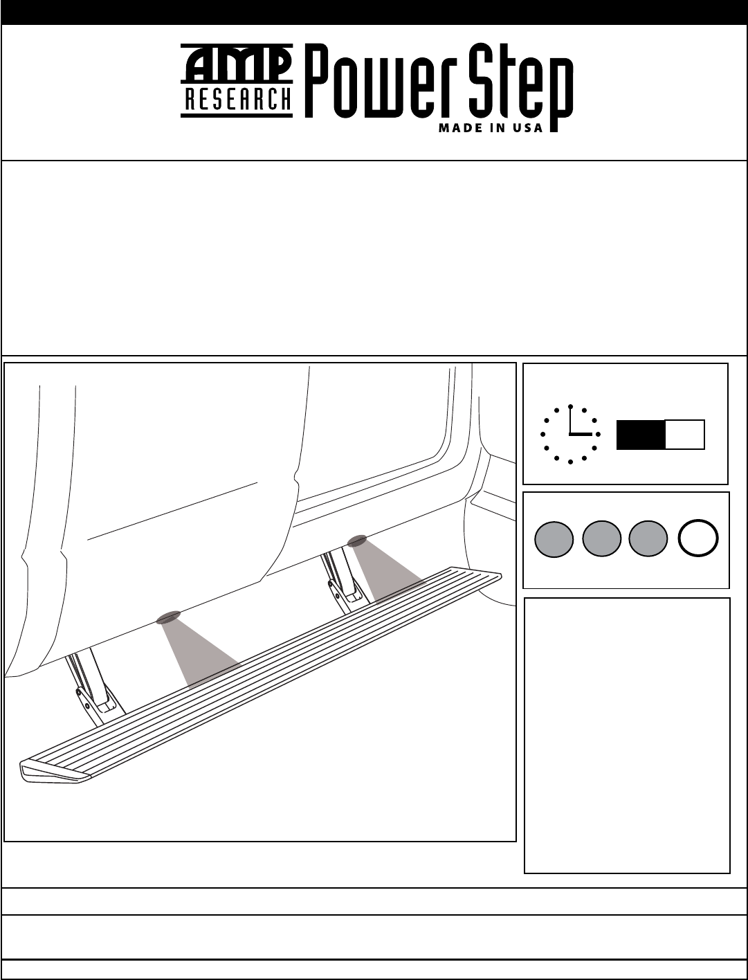
INSTALLATION GUIDE
APPLICATION MODEL YR AMP PART #
Dodge Ram Quad Cab 1500 2002 - 2008 75101-01A
Dodge Ram Quad Cab 2500/3500 2003 - 2009 75101-01A
Dodge Ram Mega Cab 2006 - 2009 75118-01A
4
TOOLS REQUIRED
q Safety goggles
q Measuring tape
q Flat blade screwdriver
q Phillips head screwdriver
q Right angle drill
q 1/8” drill bit
q 13 mm socket
q Ratchet wrench and extension
q Soldering iron
q Wire crimpers
q Wire stripper / cutter
q Corrosion inhibiter
q 3/16” hex key wrench (allen wrench )
q 1/8” hex key wrench (allen wrench)
q 4 mm hex key wrench (allen wrench )
q Pop rivet tool
q Electrical tape
INSTALLATION TIME
1
2 3
4
SKILL LEVEL
4= Experienced
3:00
hrs
AMP RESEARCH TECH SUPPORT 1-888-983-2204 (Press 2)
Monday - Friday, 6:00 AM - 5:00 PM PST
Designed and manufactured by AMP Research
®
. Patent Number 6,830,257; 6,641,158; 6,834,875; 6,938,909; 6,942,233; 7,007,961; 7,055,839; 7,163,221;
7,367,574; 7,380,807; 7,398,985; 7,413,204; 7,487,986. Other US and Worldwide patents pending. Made in USA © 2010 AMP Research
5-year limited warranty. Professional installation is recommended.
www.amp-research.com
2/11
IM2770 rev 06.08.10
AMP RESEARCH POWER STEP – DODGE RAM
INSTALLATION GUIDE
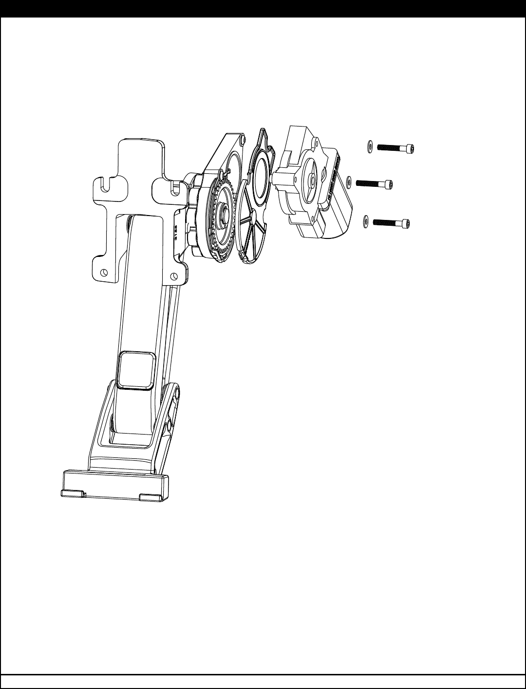
Attaching motor to linkage assembly
The motors need to be installed before continuing with the rest of the Power
Step install.
EXPLODED VIEW
19-03129-11 Motor
19-03179-90 Socket cap screw
19-03133-90 Washer
CAUTION: HANDLE WITH CARE.
To insure our customers receive all components with full integrity, we pack
the motors seperate from their linkage assemblies. This requires that the
installer position and fasten the motor before continuing with the install.
Please follow the instructions below and handle the assembly carefully.
CAUTION: Dropping the assembly or any excessive impact MAY cause
damage to the motor.
Instructions:
1. Position the gear cover in place as shown if not already in place.
2. Seat motor into position on the three mounting bosses. This may require
an adjustment of the gear by moving the swing arms.
3. After seating into place, fasten the motor with the three motor mount
screws with T30 Torx. Tighten screws to 80 in-lbs (9N-m). Do not over
torque.

www.amp-research.com
3/11
IM2770 rev 06.08.10
AMP RESEARCH POWER STEP – DODGE RAM
1
x2
Running board assembly
3
10-02820-10 (Quad Cab)
10-02820-11 (Mega Cab)
Driver Rear Bracket
4
10-02821-10
Passenger Rear Bracket
2
x2
10-02819-10
Front Bracket
7
19-02774-91
Wire Harness
PARTS LIST AND HARDWARE IDENTIFICATION
8
19-03297-93
Controller
DRIVER REAR BRACKET
PASSENGER REAR BRACKET
6
10-02814-16
Motor Linkage
x2
5
10-02815-16
Idler Linkage
x2
C
E
D
B
A
(A) 19-03225-11 End cap left (x1)
(B) 19-03225-12 End cap right (x1)
(C) 19-02663-90 T-nut insert (x2)
(D) 19-03236-90 Socket cap screw (x2)
(E) 19-03237-90 Nut plate (x2)
20-03314-XX

www.amp-research.com
4/11
IM2770 rev 06.08.10
AMP RESEARCH POWER STEP – DODGE RAM
9
x8
19-02781-90
Hex Bolt
10
x4
19-02782-90
Hex Bolt
11
x8
19-02802-90
Socket Cap Screw
13
x4
19-02777-90
Mounting Insert
12
x8
19-02784-90
Blind Rivet
14
x25
19-02805-90
Cable tie (7”)
15
x2
19-03339-90
Cable tie (11”)
PARTS LIST AND
HARDWARE
IDENTIFICATION
17
19-03354-90
Damper Bracket Kit
(Only needed for 1500 Quad Cab)
16
x4
19-03354-90
Posi-Taps™ (Red/Grey)
www.amp-research.com
5/11
IM2770 rev 06.08.10
AMP RESEARCH POWER STEP – DODGE RAM
1
3 4
5
2
6 7
FRONT
13
3
10
DRIVER REAR BRACKET SHOWN
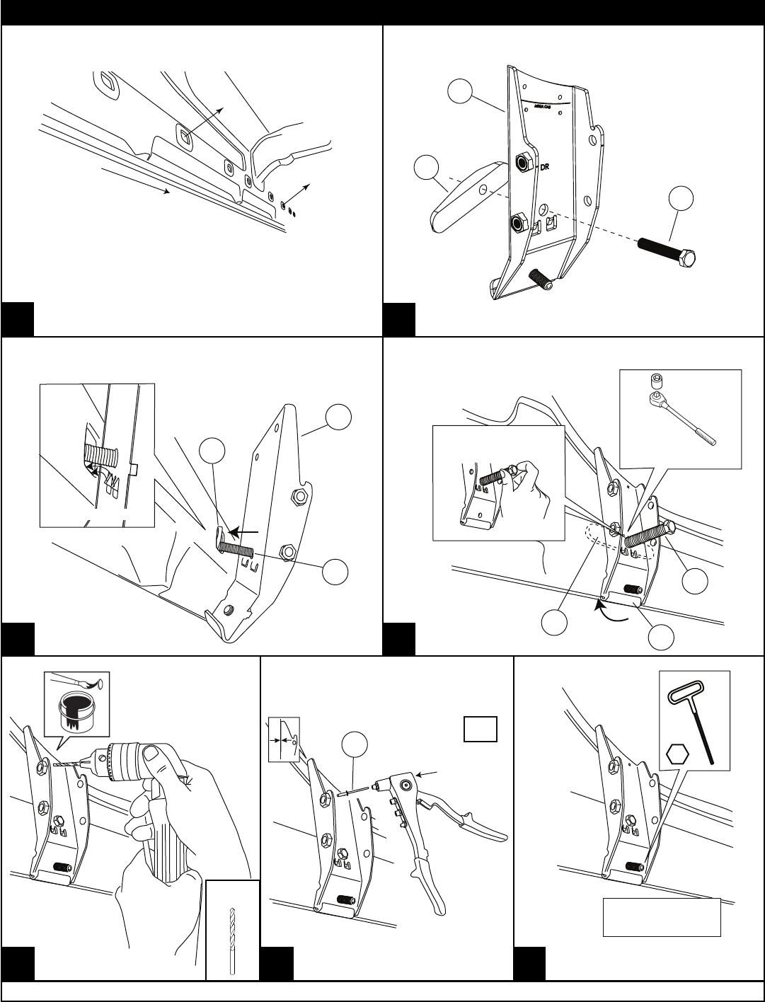
Prepare brackets for install
NOTE FOR MEGA CAB:
Remove tape and cut as
indicated for Mega Cab
rear driver bracket if not
already done.
Install rear mounting bracket
13
3
10
TABS REST ON EDGE
TORQUE
16 ft-lbs. (22 N-m)
13 mm
(PULL BACK ON BOLT
WHILE TIGHTENING)
13
3
10
Fasten down rear mounting bracket
After drilling apply
paint to prevent
rusting.
Bracket must be flush with the
sidewall before riveting.
X2
12
TORQUE
1.5 ft-lbs. (2 N-m)
1/8"
Note: Steps 1-8 shown on driver side.
Repeat these steps on passenger side.
Counting large oval sill holes from the front,
remove covering (plug or tape) from the
below indicated mounting points.
QUAD CAB: 3rd and 7th from the front.
MEGA CAB: 3rd and 8th from the front.
1/8”
www.amp-research.com
6/11
IM2770 rev 06.08.10
AMP RESEARCH POWER STEP – DODGE RAM
9
10
11
8
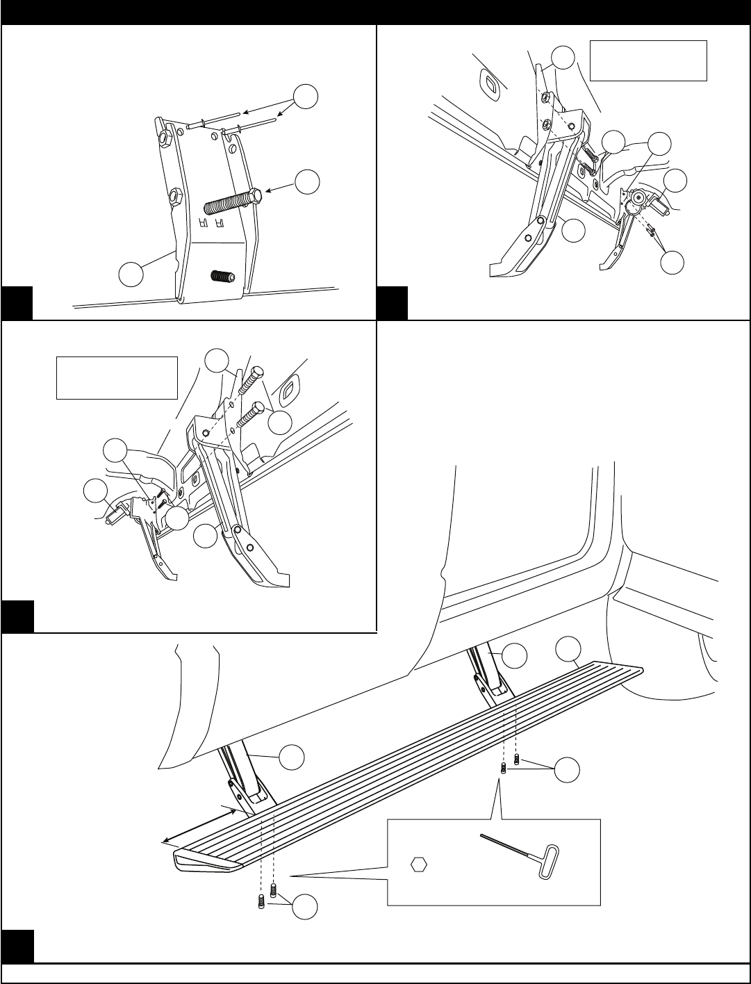
Repeat steps 2 thru 6 for front
mounting bracket.
2
10
12
3
2
9
9
5
6
DRIVER SIDE
TORQUE
16 ft-lbs. (22 N-m)
CAUTION: Swing in idler arm can
cause pinch point.
Install rear mounting bracket
4
2
6
9
5
9
TORQUE
16 ft-lbs. (22 N-m)
CAUTION: SWING IN IDLER ARM
CAN CAUSE PINCH POINT
4
Mount step extrusion to linkage assemblies.
Fasten loosely to allow for adjustments.
11"
6
1
5
1
1
1
1
3/16"
TORQUE
10 ft-lbs. (13.5 N-m)
www.amp-research.com
7/11
IM2770 rev 06.08.10
AMP RESEARCH POWER STEP – DODGE RAM
15
13 14
12
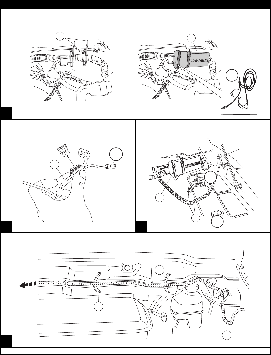
Attach 11” cable ties loosely around
harness.
Attach wire harness to the control box.
Slide controller through cable ties. Line up
cable ties with grooves in controller and
tighten.
15
7
8
Remove fuse from Power Step wire harness.
+
7
7
14
14
Route long leg of wire harness to passenger side across fire wall. Secure with tie wraps.
7
_
+
GROUND
Attach power leads, red lead to positive
battery terminal and the black lead to body
ground as shown.
8
Note: Make sure controller con-
nector locking tabs fully engage.

www.amp-research.com
8/11
IM2770 rev 06.08.10
AMP RESEARCH POWER STEP – DODGE RAM
16 17
18
19
20
7
8
UNTERMINATED WIRES
+
UNDER SIDE OF VEHICLE
7
7

www.amp-research.com
9/11
IM2770 rev 06.08.10
AMP RESEARCH POWER STEP – DODGE RAM
22
21
23
24
Remove plastic panel beneath steering column.
Remove metal panel revealed by step 21.
Model years 2002-2005 will not have this
panel to remove.
A/C vent ( left of steering column )
Parking break release
Dash light dimmer
25
Locate bundle of wires high
and to the left of diecast
steering column mount.
Note: Bundle of wires leads
toward back of fuel guage
and is located directly above
bundle of wires grounded to
left panel.
Pull wires through and
run them up to the wires
found in the previous
step.
Grey Plug
Remove the cluster and instrument panel to access the grey plug.

www.amp-research.com
10/11
IM2770 rev 06.08.10
AMP RESEARCH POWER STEP – DODGE RAM
Strip 3/8”
Insert and
Tighten
Strip 3/8”
Insert and
Tighten
(Drive/Rear)
(Drive/Front)
27
26
28 29
30
31
VT/WT
VT/WT
VT/YL
VT/YL
VT/GY
VT/GY
VT
VT
TN/RD
VT/WT
TN/Y
VT/YL
VT/OR
VT/GY
TN
VT
7
14
2X BOTH SIDES
7
REINSTALL FUSE
6
7
2X BOTH SIDES
OPEN DOORS TO TEST
Using supplied Posi-
Tap s
TM
splice the Power
Step trigger wires into
their corresponding
door ajar wire. See
steps 26 and 27 for wire
colors.
Note: You may fi nd two VL/YL wires in
bundle. Only one works correctly.
(Pass/Rear) (Pass/Front)
(Drive/Rear)
(Drive/Front)
(Pass/Rear)
(Pass/Front)
Model Year 2004- 2009
Model Year 2002- 2003

amp-research.com
LIMITED WARRANTY
WARNING
Congratulations on the purchase of your
AMP Research Power Step
Here’s what you should know...
OPERATION
The AMP Research Power Step automatically deploys when at least one door opens and automatically retracts under
your vehicle when both front and rear doors close. If resistance or blockage is encountered while the Power Step is
in motion, the drive system is designed to automatically stop. To reset, simply open or close the vehicle door and the
Power Step will resume normal operation.
MAINTENANCE TIPS
The stepping surface and drive mechanism can be wash with mild soap and water using a soft brush or sponge to
dislodge any mud, dirt or accumulated road grime. Rinse with fresh water.
To prevent slipping, avoid applying waxes, lubricants or protectants like Armor All
®
to the step surface.
When washing your vehicle, the Power Steps can be set to remain deployed with the doors closed for easy clean-
ning. Do this...
1 With the Power Step deployed, press and hold the board down with your foot.
2 Close the door while continuing to press down the board. (This will not harm motor.)
3 To reset the Power Step, simply open and close the door. (Repeat for both sides of vehicle.)
CAUTION! BE SURE TO KEEP HANDS AWAY WHEN THE POWER STEP IS IN MOTION.
AMP RESEARCH warrants product to be free from defects in material and workmanship, for terms specied below, provided
there has been normal use and proper maintenance. All remedies under this warranty are limited to the repair or replace-
ment of any item found by the factory to be defective within the time period specied.
If you have a warranty claim, rst you must call our factory at the number below for instructions. You must retain proof of
purchase and submit a copy with any items returned for warranty work. Upon completion of warranty work, if any, we will
return the repaired or replaced item or items to you freight prepaid. Damage to our products caused by accidents, re,
vandalism, negligence,
misinstallation, misuse, Acts of God, or by defective parts not manufactured by us, is not covered under this warranty.
THE WARRANTY TIME PERIOD IS AS FOLLOWS: 5-YEARS FROM DATE OF PURCHASE.
ANY IMPLIED WARRANTIES OF MERCHANTABILITY AND/OR FITNESS FOR A PARTICULAR PURPOSE CREATED HEREBY ARE
LIMITED IN DURATION TO THE SAME DURATION AND SCOPE AS THE EXPRESS WRITTEN WARRANTY. OUR COMPANDY SHALL
NOT BE LIABLE FOR ANY INCIDENTAL OR CONSEQUENTIAL DAMAGE.
Some states do not allow limitations on how long an implied warranty lasts, or the exclusion or limitation of incidental or
consequential damages, so the above limitations or exclusions may not apply to you. This warranty gives you specic legal
rights, and you may also have other rights that vary from state to state.
Be sure to read and precisely follow the provided instructions when installing this product. Failure to do so could place the
vehicle occupants in a potentially dangerous situation. After installing or reinstalling, re-check to insure that the product is
