
Packing Data
Power Cables
Catalog Number 2090-CPBM6DF-16AAxx,
2090-CPWM6DF-16AAxx, 2090-DANPT-16Sxx,
2090-XXNPH-16Sxx, 2090-XXNPHF-14Sxx, 2090-MCNPMP-6Sxx,
2090-XXNPMP-8Sxx, 2090-XXNPMF-10Sxx,
2090-XXNPMF-14Sxx, 2090-XXNPMF-16Sxx, 2090-XXNPN-16Sxx,
2090-XXNPT-16Sxx, 2090-XXNPY-16Sxx
About This Publication
This publication provides cable schematics with wire color and connector
pinouts for power cables used with Kinetix Motion Control products.
Before You Begin
The Kinetix Motion Control Selection Guide, publication GMC-SG001,
contains information on cable compatibility with specific drives and motors. It
also provides information on the bend offset and bend radius for each cable.
Refer to your drive manual for instructions to correctly interface the cables in
this document to your drive and motor combination.
Topic Page
Before You Begin 1
Cable Installation Guidelines 2
Schematics and Connector Pinouts for Power Cables 3
2090-CPBM6DF-16AAxx 3
2090-CPWM6DF-16AAxx 4
2090-DANPT-16Sxx 4
2090-MCNPMP-6Sxx, 2090-XXNPMP-8Sxx, 2090-XXNPH-16Sxx,
2090-XXNPHF-14Sxx
5
2090-XXNPMF-10Sxx 5
2090-XXNPMF-14Sxx, 2090-XXNPMF-16Sxx 6
2090-XXNPMP-10Sxx, 2090-XXNPMP-14Sxx, 2090-XXNPMP-16Sxx 6
2090-XXNPN-16Sxx 7
2090-XXNPT-16Sxx 7
2090-XXNPY-16Sxx 7

Publication 2090-PC001B-EN-P - June 2008
2
These publications are available from your local Rockwell Automation sales
office or online at
http://www.literature.rockwellautomation.com).
Cable Installation Guidelines
Cables are stored and shipped in a coil, and they will retain this shape unless
you allow the cable to straighten itself. To straighten a cable, hang a short cable
from its mid-point or lay a long cable on the floor in a straight line. Any coiling
that persists in the cable should relax within the next twenty-four hours. Doing
this results in a cable that is easier to install.
WARNING
To avoid the hazard of electrical shock, ensure shielded power cables
are grounded at a minimum of one point. Factory supplied cables have
the following design features that prevent the build-up of electrical
energy.
· the overall braid bonded to the connector housing,
· an exposed section of the overall braid, or
· a ground wire connected to the overall braid.
If the exposed cable braid or a ground wire is present, it should be
connected to the power cable clamp, housing, or another suitable
chassis ground on the drive.
Failure to observe these safety procedures could result in personal
injury or equipment damage.
WARNING
Servo drive power must be turned off before connecting or
disconnecting the cables to the motor, and if a cable is left disconnected
at the motor end. Arcing or unexpected motion could occur if the brake,
feedback, or power cables are connected or disconnected while power
is applied to the servo drive.
Failure to observe these safety procedures could result in personal
injury or damage to the motor and equipment.
ATTENTION
The examples in this publication show all the available connections,
some of which may not be appropriate for your specific installation.
Refer to your drive installation or user manual for wiring examples
appropriate to your drive and motor application.
Do not connect unused wires. These unused wires may be trimmed and
finished as necessary to prevent accidental contact with other wires or
wire shields, or with a ground connection.
Failure to observe these safety procedures could result in personal
injury or damage to the motor and equipment.

Publication 2090-PC001B-EN-P - June 2008
3
Before bending a cable, verify that the correct offset from the connector is
provided. This offset should be equal to or greater than one times (1x) the
cable diameter.
All cables have a specified bend radius, and cables should not be bent with a
rad
ius that is tighter than the specified bend radius.
• Cables have a static or one-time bend radius of ten times (10x) the cable
diameter
.
• Flex cables have an operational bend radius of twelve times (12x) the
cable diameter.
You may identify the connections for a cable by attaching a label around the
o
uter insulation of each wire adjacent to the drive connection.
Schematics and Connector
Pinouts for Power Cables
These diagrams detail cable wiring and pinouts.
2090-CPBM6DF-16AAxx
ATTENTION
Do not tightly gather or coil the excess length of a power cable. Heat is
generated within a cable whenever power is applied. Always position a power
cable so it may freely dissipate any heat.
A power cable should not be coiled, except for temporary use when building or
testing a machine. If you temporarily coil a power cable, you must also derate
the cable to meet local code or follow a authoritative directive, such as
Engineering Section 310.15(C) of the NEC Handbook.
Failure to observe these safety procedures could result in personal injury or
equipment damage.
3 12
645
978
1
2
3
5
7
9
4
6
8
16 AWG Brown
16 AWG Black
16 AWG Blue
16 AWG Green/Yellow
18 AWG White
18 AWG Black
18 AWG Drain
16 AWG Drain
N/C
N/C
N/C
U
V
W
GND
MBRK+
MBRK-
Shield exposed
for connection to
ground.
Twisted Pairing of Wires
Shield
Wire Connection (Heatshrink insulates wire-to-wire connection.)
To
Motor
To
Drive

Publication 2090-PC001B-EN-P - June 2008
4
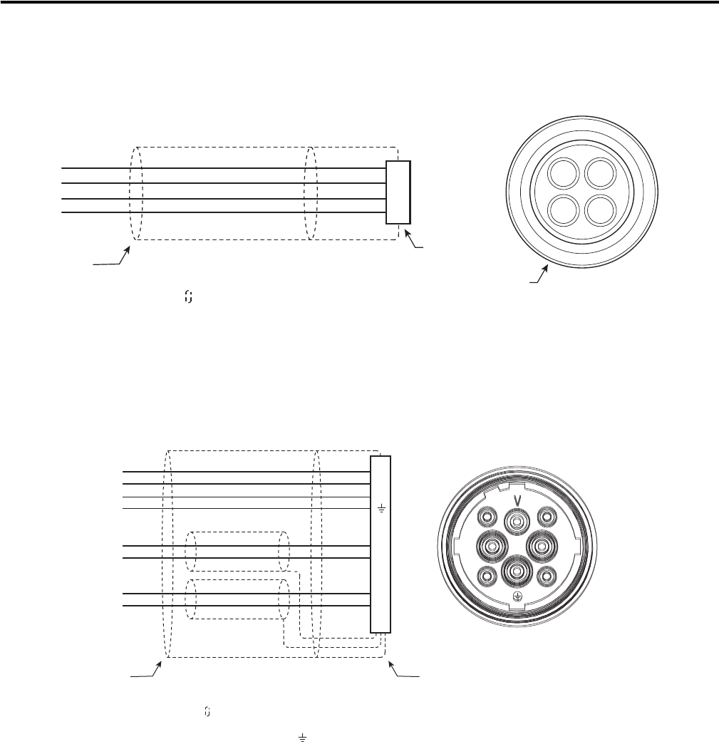
2090-CPWM6DF-16AAxx
2090-DANPT-16Sxx
1 Ground lug is located on the heatsink of on the Ultra 1500 drive. Do NOT connect this wire to the N Terminal
(DC Bus Neg) on the Ultra 1500 drive.
3 12
645
978
1
2
3
5
4
6
7
8
9
16 AWG Brown
16 AWG Black
16 AWG Blue
16 AWG Green/Yellow
Drain
U
V
W
GND
N/C
N/C
N/C
N/C
N/C
16 AWG Brown
16 AWG Black
16 AWG Blue
16 AWG Green/Yellow
Drain
Shield exposed
for connection to
ground.
Shield
Wire Connection
(Heatshrink insulates wire-to-wire connection.)
To
Motor
To
Drive
1
2
3
4
1
2
3
4
16 AWG Brown
16 AWG Black
16 AWG Blue
16 AWG Green/Yellow
Green
16 AWG
Green
U
V
W
GND
1
Ground
Lug
Shield
Wire Connection
(Heatshrink insulates wire-to-wire connections.)
Connection to
machine frame
ground required.
To
Motor
To
Drive
Publication 2090-PC001B-EN-P - June 2008
5
2090-MCNPMP-6Sxx, 2090-XXNPMP-8Sxx, 2090-XXNPH-16Sxx,
2090-XXNPHF-14Sxx
1 Power wire gauge (6, 8, 14, or 16 AWG) varies based on motor and power requirements. Refer to Kinetix
Motion Control Selection Guide, publication GMC-SG001, for additional information.
2090-XXNPMF-10Sxx
1 Contact (GND) is connected to the backshell internal to the connector.
AD
CB
A
B
C
D
U
V
W
GND
Brown
Black
Blue
Green/Yellow
1
1
1
1
Shield exposed
for connection
to ground.
Shield
Connector
backshell
shielded 360°.
To
Motor
To
Drive
Connector keying varies.
V
U W
-
+
21
V
U W
-
+
21
U
V
W
+
-
1
2
1
MBRK+
MBRK-
18 AWG White
18 AWG Black
U
V
W
GND
18 AWG White
18 AWG Red
SPARE+
SPARE-
10 AWG Brown
10 AWG Black
10 AWG Blue
10 AWG Green/Yellow
Shields exposed for
connection to ground.
Shield
Connector backshell
shielded 360°.
To
Motor
To
Drive

Publication 2090-PC001B-EN-P - June 2008
6
2090-XXNPMF-14Sxx, 2090-XXNPMF-16Sxx
1 Contact D (GND) connection to the backshell is internal to the connector.
1 Power wire gauge (14 or 16 AWG) varies based on motor and power requirements. Refer to Kinetix Motion
Control Selection Guide, publication GMC-SG001, for additional information.
2090-XXNPMP-10Sxx, 2090-XXNPMP-14Sxx,
2090-XXNPMP-16Sxx
1 Contact D (GND) connection to the backshell is internal to the connector.
2 Power wire gauge (10, 14, or 16 AWG) varies based on motor and power requirements. Refer to Kinetix Motion
Control Selection Guide, publication GMC-SG001, for additional information.
BC
G
F
A
H
E
D
L
A
B
C
D
F
G
E
H
L
Brown
Black
Blue
Green/Yellow
MBRK+
MBRK-
18 AWG White
18 AWG Black
U
V
W
GND
18 AWG White
18 AWG Red
N/C
SPARE+
SPARE-
2
2
2
2
1
Shield exposed
for connection
to ground.
Shield
Connector backshell
shielded 360°.
To
Motor
To
Drive
AD
CB
Brown
Black
Blue
Green/Yellow
A
B
C
D
U
V
W
GND
2
2
2
2
1
Shield
Connector
backshell
shielded 360°.
To
Motor
To
Drive

Publication 2090-PC001B-EN-P - June 2008
7
2090-XXNPN-16Sxx
2090-XXNPT-16Sxx
2090-XXNPY-16Sxx
1 Each wire has its respective pin number printed on the wire insulation.
A
DC
EB
A
B
C
D
E
16 AWG Brown
16 AWG Black
16 AWG Blue
16 AWG Green/Yellow
U
V
W
GND
N/C
Shield
Connector
backshell
shielded 360°.
To
Motor
To
Drive
Shields exposed
for connection to
ground.
1
2
3
4
1
2
3
4
16 AWG Brown
16 AWG Black
16 AWG Blue
16 AWG Green/Yellow
16 AWG
Green
U
V
W
GND
Shield
Wire Connection
(Heatshrink insulates wire-to-wire
connection.)
Connection to
machine frame
ground required.
To
Motor
To
Drive
Shield exposed
for connection to
ground.
1
2
3
4
5
6
7
8
9
312
645
978
16 AWG Black
16 AWG Black
16 AWG Black
16 AWG Green/Yellow
16 AWG Black
16 AWG Black
16 AWG
Black
U
V
W
GND
MBRK+
MBRK-
N/C
N/C
N/C
1
1
1
1
1
Shield
Wire Connection
(Heatshrink insulates
wire-to-wire connection.)
Connection to
machine frame
ground required.
To
Motor
To
Drive
Shield exposed
for connection
to ground.

Publication 2090-PC001B-EN-P - June 2008 8 PN-18471
Supersedes Publication 2090-PC001A-EN-P - June 2008 Copyright © 2008 Rockwell Automation, Inc. All rights reserved. Printed in the U.S.A.
Rockwell Automation Support
Rockwell Automation provides technical information on the Web to assist you in using its products. At
http://support.rockwellautomation.com
, you can find technical manuals, a knowledge base of FAQs, technical and application
notes, sample code and links to software service packs, and a MySupport feature that you can customize to make the best use of
these tools.
For an additional level of technical phone support for installation, configuration, and troubleshooting, we offer TechConnect
support programs. For more information, contact your local distributor or Rockwell Automation representative, or visit
http://support.rockwellautomation.com
.
Installation Assistance
If you experience a problem within the first 24 hours of installation, please review the information that's contained in this manual.
You can also contact a special Customer Support number for initial help in getting your product up and running.
New Product Satisfaction Return
Rockwell Automation tests all of its products to ensure that they are fully operational when shipped from the manufacturing
facility. However, if your product is not functioning and needs to be returned, follow these procedures.
Allen-Bradley, Rockwell Automation, and TechConnect are trademarks of Rockwell Automation, Inc.
Trademarks not belonging to Rockwell Automation are property of their respective companies.
United States 1.440.646.3434
Monday – Friday, 8 a.m. – 5 p.m. EST
Outside United States Please contact your local Rockwell Automation representative for any technical support issues.
United States Contact your distributor. You must provide a Customer Support case number (call the phone
number above to obtain one) to your distributor in order to complete the return process.
Outside United States Please contact your local Rockwell Automation representative for the return procedure.
