
VMware Telco Cloud
Automation Deployment
Guide
VMware Telco Cloud Automation 2.0
VMware Telco Cloud Automation Control Plane 2.0
VMware Telco Cloud Automation Manager 2.0
You can find the most up-to-date technical documentation on the VMware website at:
https://docs.vmware.com/
VMware, Inc.
3401 Hillview Ave.
Palo Alto, CA 94304
www.vmware.com
Copyright
©
2020 VMware, Inc. All rights reserved. Copyright and trademark information.
VMware Telco Cloud Automation Deployment Guide
VMware, Inc. 2
Contents
About This Guide 6
1 Overview 7
2
Planning for Installation 9
3
System Requirements
12
HA-Based System Requirements 12
Non HA-Based System Requirements 13
4 Ports and Protocols 15
5
Software Version Support and Interoperability 16
6
Deploying HA Based Cloud Native VMware Telco Cloud Automation Using Scripts
19
Prerequisites For Running the Script 19
Run the Script 24
7 Deploying HA-Based VMware Telco Cloud Automation Using Infrastructure
Automation 29
Initial Configuration and Bootstrapping 29
Install VMware vSphere ESXi 29
Deploy VMware Telco Cloud Automation Bootstrapper Virtual Machine 30
High Availability Specific Configurations 30
Deploying Telco Cloud Automation through Infrastructure Automation 31
Deployment Configurations 31
Specification File for Cloud Native 31
Configure Global Settings 44
Add Images or OVF 45
Configure Appliances 46
Add Certificate Authority 49
Managing Domains 49
Add Management Domain 50
Add Workload Domain 56
Add Compute Cluster 62
Add a Cell Site Group 66
Add Host to a Site 69
VMware, Inc.
3
Certificate Management 70
8 Deploying Non HA-Based VMware Telco Cloud Automation 72
Installing the System 72
Downloading the VMware Telco Cloud Automation OVA File 72
Deploying the VMware Telco Cloud Automation OVA in the vSphere Client 73
Activating Your Appliances 74
Configuring the Appliances 78
9
Configuring an Airgap Repository
83
Airgap Server Deployment Topologies 83
Prerequisites for Setting up the Airgap Repository 87
Set up the Airgap Server 88
Export the Airgap Server Virtual Appliance 90
Deploy Airgap Servers from the Airgap OVA 90
Build an Airgap Server for Upgrading VMware Telco Cloud Automation 92
Validate Airgap Server Setup 94
Upgrade Repositories on the Airgap Server 95
Upgrade Existing Airgap Servers 96
Inline Upgrade: Synchronize Packages and Images of a New VMware Telco Cloud Automation
Build 97
Troubleshooting Airgap Server Setup 98
10 Upgrading the Airgap Server and High Availability 100
11 Managing System Settings 102
Network Ports and Protocols 102
Understanding the Appliance Management Dashboard 104
Updating the Time Settings 106
Updating the System Name 107
Managing CA and Self-Signed Certificates 107
Update Server Certificate 107
Reboot an Appliance 108
Change Appliance Password 109
Update License Key 109
Backing Up and Restoring the System 110
Backing Up VMware Telco Cloud Automation Control Plane 110
Restoring the System 112
Restoring the Appliance 112
Technical Support Logs 113
Upgrading Standalone VMware Telco Cloud Automation Appliances 114
VMware Telco Cloud Automation Deployment Guide
VMware, Inc. 4
About This Guide
VMware
®
Telco Cloud Automation has two component services: VMware Telco Cloud Automation
Manager and VMware Telco Cloud Automation Control Plane (TCA-CP). The
VMware Telco Cloud
Automation Deployment Guide
describes how to plan for installation of these components and
how to deploy them. It includes step-by-step installation and activation procedures.
Intended Audience
This information is for anyone who wants to deploy and activate the VMware Telco Cloud
Automation Manager and TCA-CP services. For information on how to use VMware Telco Cloud
Automation, see the
VMware Telco Cloud Automation User Guide
.
VMware Technical Publications Glossary
VMware Technical Publications provides a glossary of terms that might be unfamiliar to you. For
definitions of terms used in the VMware technical documentation, go to http://www.vmware.com/
support/pubs.
VMware, Inc.
6

Overview
1
The VMware Telco Cloud Automation Control Plane (TCA-CP) and VMware Telco Cloud
Automation Manager components work together to provide VMware Telco Cloud Automation
services.
VMware Telco Cloud Automation has various benefits:
n Multi-cloud operational management, simplifying the design, onboarding, and management of
both network functions and services across data centers and tenants of the Telco Cloud.
n Streamlining of the CSP orchestration with a native integration into VMware cloud
technologies.
n Building Telco Cloud architectures with open multi-vendor Telco Cloud eco systems.
VMware Telco Cloud Automation Manager provides orchestration and management services for
Telco clouds. Through VMware Telco Cloud Automation, you connect the virtual infrastructure in
the Telco edge, aggregation, and core sites using VMware Telco Cloud Automation Control Plane.
VMware Telco Cloud Automation
Site 1
VNF / CNF
VMware Telco Cloud
Automation Control Plane
TCA
orchestration
VMware Telco Cloud
Automation Control Plane
VNF CNF VNF CNF
CNF VNF CNF VNF
Site X
VNF / CNF
CNF VNF CNF VNF
VNF CNF VNF CNF
VMware, Inc.
7
VMware Telco Cloud Automation Control Plane (TCA-CP) provides the infrastructure abstraction
for placing workloads across clouds using Telco Cloud Automation. VMware Telco Cloud
Automation Control Plane supports the following virtual infrastructure manager (VIM) types:
VMware vSphere, VMware Cloud Director, OpenStack, Kubernetes, Amazon EKS, VMware Cloud
on AWS, Google Cloud, Azure, and IBM Cloud.
This guide provides the instructions for installing and activating both the TCA-CP and Telco Cloud
Automation Manager components. For information about using VMware Telco Cloud Automation,
see the
VMware Telco Cloud Automation User Guide
.
VMware Telco Cloud Automation Deployment Guide
VMware, Inc. 8

Planning for Installation
2
Deploying the VMware Telco Cloud Automation Manager-Control Plane and VMware Telco Cloud
Automation Manager appliances require information about your vCenter Server sites, networks,
and configurations.
You can deploy VMware Telco Cloud Automation in the following ways:
n Cloud-native HA-based deployment.
n VM-based deployment.
This guide covers both deployment types.
Note
n To ensure high availability in a VM-based deployment, deploy the VMware Telco Cloud
Automation Manager-Control Plane and VMware Telco Cloud Automation Manager appliances
on a vSphere HA-enabled cluster. When the primary ESXi host where the virtual machine is
deployed becomes unavailable, vSphere HA migrates the virtual machine to a secondary ESXi
host and the appliances are restored. Restoration time can vary according to the environment,
but ideally, it takes between 5 and 10 minutes to restore the appliances and its services. For
more information about vSphere HA, see vSphere HA. This option is not applicable for a
cloud-native VMware Telco Cloud Automation appliance.
n For cloud native deployment, ensure that the prefix length in IP is less than or equal to 27 (i.e.
30 IP addresses) to ensure that the subnet has sufficiently IP addresses for appliances.
Collecting the required configuration details in advance can greatly reduce the time and resources
to deploy. Use the checklists provided in this document for pre-installation planning.
Installation Checklist
This installation checklist applies to both VMware Telco Cloud Automation Manager-Control Plane
and VMware Telco Cloud Automation Manager.
Note If you are installing VMware Telco Cloud Automation Manager-Control Plane with VMware
Cloud Director, gather additional information as listed in "Installation Checklist for VMware Cloud
Director."
VMware, Inc.
9

Checklist item Details
Software versions Verify that VMware software versions meet the minimum
requirements. See Chapter 5 Software Version Support and
Interoperability.
License key Obtain the key from your VMware account team.
Installer OVA downloaded Download the installer OVA before the installation date.
Service account available on vCenter Verify that a service account with administrator privileges
exists in the vCenter.
NSX preparation and credentials (Not required for installing VMware Telco Cloud Automation
Manager)
n Determine that all hosts in the cluster are NSX prepared
and the transport zone is known.
n Verify the NSX Manager credentials, which are required
to pair VMware Telco Cloud Automation Manager-
Control Plane with the NSX Manager.
Cluster or Resource Pool name Confirm the location where the components are deployed.
Network name Identify the Distributed Virtual Port Group name to which
the VMware Telco Cloud Automation Manager-Control
Plane connects.
IP address for component Manager Confirm the IP address assigned to the VMware Telco Cloud
Automation Manager-Control Plane or VMware Telco Cloud
Automation Manager component on the Management
VLAN.
Prefix length Confirm the prefix length of the Management VLAN.
Gateway IP address Confirm the IP address of the Management VLAN gateway.
Datastore Identify the datastore where the VMware Telco Cloud
Automation Manager-Control Plane and VMware Telco
Cloud Automation Manager components are deployed.
Each requires a minimum of 60 GB.
DNS Server Verify the IP address and hostname of the DNS Server.
Name resolution is required for activation and for the
VMware Telco Cloud Automation components.
Network Time Protocol Server name Verify the IP address and hostname of the NTP Server.
Time synchronization is required for activation and for the
VMware Telco Cloud Automation components.
Note All vSphere components must be synchronized using
NTP.
vRealize Orchestrator credentials Gather the administrative credentials for vRealize
Orchestrator.
VMware Telco Cloud Automation Deployment Guide
VMware, Inc. 10

Installation Checklist for VMware Cloud Director
Deployments
Gather these installation details when installing VMware Telco Cloud Automation Manager-Control
Plane in VMware Cloud Director environments.
Checklist Item Details
Org quotas Take note of Quotas present on the Org. For example, this
quota can be a virtual machine limit. Determine how many
vCenters and NSX servers are configured in VMware Cloud
Director.
VMware Cloud Director credentials Gather the system administrator credentials for configuring
VMware Telco Cloud Automation Manager-Control Plane
with VMware Cloud Director.
vCenter and NSX credentials Gather the administrative credentials for both the vCenter
Server and NSX Manager.
vRealize Orchestrator credentials Gather the administrative credentials for vRealize
Orchestrator.
VMware Cloud Director notifications n Determine if RabbitMQ (RMQ) is enabled in VMware
Cloud Director.
n Identify the RMQ type. Only non-SSL or SSL with
credentials is supported.
n Gather the RMQ Notifications user name and password.
VMware Cloud Director public addresses Determine if VMware Cloud Director public addresses are
set:
n API: VMware Cloud Director secure public REST API
base URL
n API: VMware Cloud Director secure public REST API
certificate chain
n Web Console: VMware Cloud Director secure public
URL
n Web Console: VMware Cloud Director secure certificate
chain
VMware Telco Cloud Automation Deployment Guide
VMware, Inc. 11

System Requirements
3
This section lists the system requirements for deploying VMware Telco Cloud Automation in
the High Availability (HA) and non-HA modes. Appliances using the cloud-native deployment
method are deployed in the HA mode and appliances using the VM-based deployment method
are deployed in the non-HA mode.
This chapter includes the following topics:
n HA-Based System Requirements
n Non HA-Based System Requirements
HA-Based System Requirements
If you are deploying VMware Telco Cloud Automation in the High Availability (HA) mode,
ensure that your system meets the following requirements in addition to the general system
requirements.
Note The requirements listed in this section are the minimum resource requirements for
deploying VMware Telco Cloud Automation in the HA mode. The total resource requirements
can vary depending on the number of domains you configure in your environment.
Bootstrapper Virtual Machines
One VMware Telco Cloud Automation bootstrapper virtual machine per management domain and
workload domain. For example, a Central Site management domain has one bootstrapper virtual
machine and every workload domain has one bootstrapper virtual machine.
VMware Telco Cloud Automation Clusters
Clusters are required for running the VMware Telco Cloud Automation Manager and the VMware
Telco Cloud Automation Control Plane services on different namespaces. The VMware Tanzu
Kubernetes Grid cluster is where VMware Telco Cloud Automation and other third party services
run. The cluster requirements are:
Components
Control Plane Node Worker Node
Replicas 3 3
CPU 8 8
VMware, Inc. 12

Components Control Plane Node Worker Node
Memory 16384 MB 16384 MB
Disk Space 50 GB 50 GB
Bootstrapper Cluster
Note Required only on setups that include the VMware Telco Cloud Automation Control Plane.
Components Control Plane Node Worker Node
Replicas 1 1
CPU 2 2
Memory 4 GB 4 GB
Disk Space 50 GB 50 GB
IP Addresses
Component Number of IP Addresses
Bootstrapper Virtual Machine One for each virtual machine.
Control Plane Endpoint IP One for each cluster.
Bootstrapper Cluster One for each cluster.
VMware Telco Cloud Automation Manager One for each instance. It must be routable to the cluster
network.
VMware Telco Cloud Automation Control Plane One for each instance. It must be routable to the cluster
network.
Non HA-Based System Requirements
Before installing or deploying VMware Telco Cloud Automation Manager and TCA-CP, consider
the minimum required resources for each component appliance and the deployment scaling
requirements.
Resource Requirements
Component
vCPU Memory Disk Space/IOPS
VMware Telco Cloud
Automation Manager
4 12 GB 60 GB
TCA-CP 4 12 GB 60 GB
Scaling Requirements
For detailed configuration limits, see https://configmax.vmware.com/home.
VMware Telco Cloud Automation Deployment Guide
VMware, Inc. 13

Component VIM Scaling Requirement
VMware Telco Cloud Automation
Manager
Not applicable One per Telco Central Site.
TCA-CP VMware vSphere Server with CaaS
Infrastructure
One per VIM. The number of
Kubernetes clusters deployed per
VIM depends on the VMware Telco
Cloud Automation version. For the
latest configuration limits, see https://
configmax.vmware.com/home.
TCA-CP VMware vSphere Server One per VIM.
TCA-CP VMware Cloud Director One per VMware Cloud Director.
Note Providing TCA-CP on one
VMware Cloud Director covers all
organizations associated with that
VMware Cloud Director.
TCA-CP VMware Integrated Open Stack (VIO) One per VIM.
TCA-CP Kubernetes cluster The number of Kubernetes Clusters
deployed per TCA-CP depends
on the VMware Telco Cloud
Automation version. For the latest
configuration limits, see https://
configmax.vmware.com/home.
For clusters that are not deployed
through VMware Telco Cloud
Automation, a single TCA-CP
appliance can manage up to 30
Kubernetes clusters.
VMware Telco Cloud Automation Deployment Guide
VMware, Inc. 14
Ports and Protocols
4
VMware Telco Cloud Automation is accessed through predetermined TCP and UDP ports. If you
manage network components from outside a firewall, you might be required to reconfigure the
firewall to allow access on the appropriate ports.
For the list of all supported ports and protocols in VMware Telco Cloud Automation, see
the VMware Ports and Protocols Tool™ at https://ports.vmware.com/home/VMware-Telco-Cloud-
Automation.
VMware, Inc. 15

Software Version Support and
Interoperability
5
This interoperability information defines the qualified components and software versions you can
use with VMware Telco Cloud Automation.
The following tables describe the supported cloud types, Kubernetes Cluster, and Tanzu
Kubernetes Grid versions for vSphere clouds, and vRealize Orchestrator versions.
Table 5-1. VMware vSphere
Cloud Version vSphere Version NSX Type NSX Version
6.7 U3 6.7 U3 NSX-T 3.0.3
7.0 U1a 7.0 U1a NSX-T 3.1.2
7.0 U1c 7.0 U1d NSX-T 3.1
7.0 U2 7.0 U2 NSX-T 3.1.2
7.0 U2d 7.0 U2d NSX-T 3.1.3
7.0 U2 7.0 U2 NSX-T 3.1.3
7.0 U3 7.0 U3 NSX-T 3.2
Note NSX versions include minor patch versions such as NSX-T version 3.1.2.1.
Table 5-2. Kubernetes and Tanzu Kubernetes Grid Support for vSphere Cloud
vSphere Cloud Version
Tanzu Kubernetes Grid
(TKG) Version
Kubernetes Version
Management Cluster Workload Cluster
6.7 U3 1.4 1.21.2 1.19.12, 1.20.8, 1.21.2
7.0 U1a 1.4 1.21.2 1.19.12, 1.20.8, 1.21.2
7.0 U2 1.4 1.21.2 1.19.12, 1.20.8, 1.21.2
7.0 U2d 1.4 1.21.2 1.19.12, 1.20.8, 1.21.2
7.0 U3 1.4 1.21.2 1.19.12, 1.20.8, 1.21.2
VMware, Inc. 16

Table 5-3. VMware Cloud Director and RabbitMQ
VMware Cloud
Director Cloud
Version vSphere Version NSX Type NSX Version Other Components
9.7 6.7 NSX-V 6.4.6
RabbitMQ - 3.7+
9.7.03 6.7 NSX-T 2.5.2
RabbitMQ - 3.7+
10 6.7 NSX-T 2.5.1
RabbitMQ - 3.7+
10.1.2 6.7 U3 NSX-T 3.0.2
RabbitMQ - 3.7+
10.2 7.0 U1 NSX-T 3.1.2
RabbitMQ - 3.7+
10.3 7.0 U2 NSX-T 3.1.3
RabbitMQ - 3.7+
Table 5-4. VMware Integrated OpenStack
VMware Integrated
OpenStack Cloud Version vSphere Version NSX Type NSX Version
7.0 6.7 U3 NSX-T 3.0.2
7.0.1
6.7 U3 NSX-T 3.0.3
7.0.1
7.0 U1 NSX-T 3.1.2
7.0.1
7.0 U2 NSX-T 3.1.3
7.1
7.0 U3 NSX-T 3.1.3
Table 5-5. Kubernetes
Kubernetes Version vSphere Version NSX Type NSX Version
1.18 6.7 U3 – 7.0 NSX-T 2.5.x - 3.1.3
1.19 6.7 U3 – 7.0 NSX-T 2.5.x - 3.1.3
1.20 6.7 U3 – 7.0 NSX-T 2.5.x - 3.1.3
Table 5-6. vRealize Orchestrator Supported
vRealize Orchestrator Version
7.6.0
8.1
8.2
8.3
8.4
VMware Telco Cloud Automation Deployment Guide
VMware, Inc. 17

Table 5-6. vRealize Orchestrator Supported (continued)
vRealize Orchestrator Version
8.4.1
8.4.2
Table 5-7. VMware Cloud on AWS
VMware Cloud on AWS Version
M16
VMware Telco Cloud Automation Deployment Guide
VMware, Inc. 18

Deploying HA Based Cloud Native
VMware Telco Cloud Automation
Using Scripts
6
You can create or delete a HA-based cloud native VMware Telco Cloud Automation appliance
using scripts.
The Bootstrapper virtual machine contains scripts and required templates for setting up a cloud
native VMware Telco Cloud Automation appliance in HA mode. The following table lists their file
locations.
File Location in Bootstrapper
Setup Script
/opt/vmware/setup_ha/setup_ha.py
Configuration File Template
/opt/vmware/setup_ha/bootstrapper_template.json
Sample Invocation
$ python3 /opt/vmware/setup_ha/setup_ha.py --config_file ~/bootstrapper.json --
skipConfirmations
This chapter includes the following topics:
n Prerequisites For Running the Script
n Run the Script
Prerequisites For Running the Script
Perform the prerequisite steps listed in this section.
Install the Bootstrapper virtual machine on a vCenter Server, optionally with vRealize Log Insight,
in an air-gapped environment. For information about setting up VMware Telco Cloud Automation
in an air-gapped environment, see
VMware Telco Cloud Automation User Guide
.
Note If you are deploying VMware Telco Cloud Automation in an air-gapped environment,
ensure that you select the Activation Mode as Standalone. For more information, see Activate
VMware Telco Cloud Automation Manager.
1 Use the VMware-Telco-Cloud-Automation-<version>.ova.
VMware, Inc.
19

2 In the Appliance Role step, select Bootstrapper as the appliance role.
3 Upload the latest Photon VM template on your vCenter Server. For example, photon-3-
kube-v1.21.2+vmware.1 for VMware Tanzu Kubernetes Grid 1.4.0. This step ensures that the
script creates management clusters and workload clusters.
4
Using the bootstrapper_template.json file located at /opt/vmware/setup_ha/
bootstrapper_template.json, create the bootstrapper.json file on the Bootstrapper
virtual machine. The following table lists the required section in the bootstrapper.json file.
Note
n Use Python version 3.6.9 or later.
n All passwords are base64 encoded.
n When deploying VMware Telco Cloud Automation in an air-gapped environment, ensure
that the CA certificates are encoded in the base64 format.
VMware Telco Cloud Automation Deployment Guide
VMware, Inc. 20

Section in bootstrapper.json Mandatory/Optional Comments
"bootstrapperVmContext": {
"ip": "<Bootstrapper
VM IPv4 or FQDN>",
"username": "<admin
user>",
"password": "<password
encoded in base64 format>"
},
Mandatory n Bootstrapper virtual machine of
appliance type tca-bootstrapper.
n Enter the Bootstrapper virtual
machine's IP address and
credentials.
"vsphereContext": {
"ip": "<Vcenter IPv4
or FQDN>",
"username": "<admin
user>",
"password": "<password
encoded in base64 format>",
"dataCenter": "/
<dataCenter>",
"dataStore": "/<dataCenter>/
datastore/<dataStoreName>",
"network": "/<dataCenter>/
network/<vmFolderName>/
<networkName>",
"resourcePool":
"/<dataCenter>/host/
<clusterName>/Resources/
<resourcePoolName>",
"vmFolder":
"/<dataCenter>/vm/
<vmFolderName>",
"vmTemplate":
"<Example: photon-3-kube-
v1.21.2+vmware.1 is the
template for TKG 1.4.0>",
"version": "<Optional.
Example: 7.0.2 Defaults to
7.0.2 when not provided.>"
},
Mandatory
n Enter the vCenter Server IP address
and credentials. The VMware Telco
Cloud Automation appliance and
Bootstrapper cluster in a cloud-
native environment is created here.
n The vCenter Server settings for
creating VMware Telco Cloud
Automation and the Bootstrapper
cluster are:
n dataCenter
n network
n resourcePool
n vmFolder
n username: A user belonging to
the Administrator (system admin)
group in vCenter Server.
n vmTemplate: The latest version of
Photon VM template according to
the VMware Tanzu Kubernetes Grid
version. For example,
photon-3-
kube-v1.21.2+vmware.1 for
VMware Tanzu Kubernetes Grid
1.4.0. For supported component
versions, see:
VMware Tanzu
Kubernetes Grid 1.4 Release Notes
at docs.vmware.com.
n version: Optional field for vSphere
version. If provided, then enter
the vSphere version. The default
version is 7.0.2.
Note Ensure that you provide
full paths for the vsphereContext
resources.
"managementCluster":{
"controlPlaneEndpointIP":
"<Management Cluster IPv4>",
"clusterPassword":
"<password encoded in
base64 format>"
},
Mandatory n Enter the external IP address of the
management cluster.
VMware Telco Cloud Automation Deployment Guide
VMware, Inc. 21

Section in bootstrapper.json Mandatory/Optional Comments
"workloadCluster":{
"controlPlaneEndpointIP":
"<Workload Cluster IPv4>",
"clusterPassword":
"<password encoded in
base64 format>"
},
Mandatory if tcaCp is provided. If you
provide tcaCp, then all the fields are
mandatory.
n The workload cluster is created
temporarily for generating a
manifest. This manifest is then
used for creating the Bootstrapper
cluster.
n Enter the external IP address of the
workload cluster.
n This section is required if tcaCp
details are provided.
"tcaMgr" : {
"ip": "<TCA IPv4>",
"platformManagerPscUrl":
"https://<Vcenter IPv4/
FQDN>",
"platformManagerPscDomain":
"<domain> example:
vsphere.local",
"platformManagerPscUsergroup
": "<Vcenter user group>
example: administrators"
},
Optional. If you include this section,
then all the fields are mandatory.
n Provide inputs for tcaMgr or tcaCp,
or both.
n In a development environment,
you can use the script to
install both appliances on the
same management cluster, under
different namespaces.
Appliance Namespace
tca tca-manager
tca-cp tca-system
VMware Telco Cloud Automation Deployment Guide
VMware, Inc. 22

Section in bootstrapper.json Mandatory/Optional Comments
"tcaCp" : {
"ip": "<TCA CP IPv4>",
"platformManagerPscUrl":
"https://<Vcenter IPv4/
FQDN>",
"platformManagerPscDomain":
"<domain> example:
vsphere.local",
"platformManagerPscUsergroup
": "<Vcenter user group>
example: administrators",
"sshPrivateKeyFile":
"<path to ssh private key
file> example /
fullPath/.ssh/id_rsa",
"sshPublicKeyFile":
"<path to ssh public key
file> example /
fullPath/.ssh/id_rsa.pub",
"sshPrivateKey": "<ssh
key files above or
bootstrapper cluster ssh
private key>",
"sshPublicKey": "<ssh
key files above or
bootstrapper cluster ssh
public key>"
},
Optional. If you include this section,
then all the fields are mandatory.
n Provide inputs for tcaMgr or tcaCp,
or both.
n To access from
bootstrapperVMContext
,
tcaCp
requires a SSH public or SSH
private key.
Note Either provide the public key
and private key in string format or as
SSH files. Do not provide the keys in a
mixed format.
Note
n In a Bootstrapper VM, you can find
the private key and the public key
under /root/.ssh/.
n In a development environment,
you can use the script to
install both appliances on the
same management cluster, under
different namespaces.
Appliance Namespace
tca tca-manager
tca-cp tca-system
"overrideValues": {
" comment": "each
entry in this section is
optional",
"vrliAddress":"<VRLI
IPv4/FQDN address> : if
VRLI Address is provided,
fluent service pod will be
installed in fluent-system
namespace",
"repoLibraryPath":"<URI
with IPv4/FQDN, port and
path for external repo like
Airgap, Jfrog > example:
10.1.9.100:8012/library",
"dnsServers":[
"<DNS server IPv4
address 1>",
"<DNS server IPv4
address 2>",
.
.
Optional Each key in this section is optional.
n vrliAddress: If present, this key
enables the installation of fluent
service. Otherwise, the installation
is skipped.
n repoLibraryPath: This key is
required in an air-gapped
environment, or if you use an
external repository for pulling
images.
n airgapFQDN: If you have set up
VMware Telco Cloud Automation in
the air-gapped environment.
n airgapCert: Applicable only when
you provide
airgapFQDN.
VMware Telco Cloud Automation Deployment Guide
VMware, Inc. 23

Section in bootstrapper.json Mandatory/Optional Comments
.
"<DNS server IPv4
address N>"
],
"airgapFQDN":"<FQDN
address> fqdn of the
airgap server> Example:
airgap.example.com",
"airgapCert": "<Optionally
needed when airgap server
is configured with self
signed cert: base64
encoded>"
}
Note You must prefix unused fields with comment_. For example, if the airgap FQDN is not
used, you must provide the following prefix: "comment_airgapFQDN":"<FQDN address> fqdn of
the airgap server> Example: airgap.example.com". Or, you can remove the unused optional
fields.
Run the Script
You can run the script with or without using the optional arguments listed in this section. Run the
script as a root user.
Run the Script without Arguments
To run the script without arguments, open a terminal and run $ python setup_ha.py.
This command deploys the following:
n Management cluster.
n Bootstrapper cluster.
n All the required namespaces with their services in the Management cluster for VMware Telco
Cloud Automation and/or VMware Telco Cloud Automation Control Plane.
If the script run is interrupted, the script verifies the installed cluster and services and deploys only
the missing components.
VMware Telco Cloud Automation Deployment Guide
VMware, Inc. 24

Run the Script with Arguments
To run the script with optional arguments:
1 Open a terminal and run $ python setup_ha.py [options]. This command lists the available
optional arguments.
$ python setup_ha.py [options]
VMware Inc.
Copyright 2021
Create/Delete cloud native TCA and/or TCA-CP appliances in HA mode.
Default is to install "all" services after installing MANAGEMENT Cluster and Bootstrapper
Cluster.
Optional arguments:
-h, --help show this help message and exit
-b, --deployBootstrapperClusterOnly deploys only Bootstrapper cluster
-d, --debug set logging level to DEBUG
-f CONFIG_FILE, --config_file CONFIG_FILE config file in JSON format. Default:./
bootstrapper.json
-i, --skipConfirmations. skip confirmations
-r, --deleteBootstrapperClusterOnly removes only Bootstrapper cluster
-s [Service_or_NameSpace], --deploy [Service_or_NameSpace]. Deploy specific service or all
services in the namespace.
-u [Service_or_NameSpace], --delete [Service_or_NameSpace]. Delete specific service or all
services in the namespace, default is "all"
-v, --validateOnly validate input file and stop
-c, --confirmOnEachApiResponse
wait for confirmation at each API Response when debug is enabled
-p, --skipBootstrapperClusterCreationDeletion
skip creating Bootstrapper cluster, storing manifest and deleting it at the end
2 Select an argument and run the script.
The following table lists the arguments and their descriptions.
VMware Telco Cloud Automation Deployment Guide
VMware, Inc. 25

Argument Description
-b, --deployBootstrapperClusterOnly This argument deploys the bootstrapper cluster only. It
saves the manifest file in a database that can be used at
a later stage.
-r, --deleteBootstrapperClusterOnly This argument deletes the bootstrapper cluster. It does not
affect any other services running in various namespaces in
VMware Telco Cloud Automation and VMware Telco Cloud
Automation Control Plane appliances.
-v, --validateOnly This argument validates the input configuration file. It does
not deploy or delete any cluster or service.
-s [Service_or_NameSpace], --deploy
[Service_or_NameSpace]
This argument deploys a specific service or all services
in the namespace. It deploys only a given service in
one or more namespaces or all the services in a given
namespace, as required by the VMware Telco Cloud
Automation appliance. This option is for troubleshooting or
development purposes only.
-u [Service_or_NameSpace], --delete
[Service_or_NameSpace]
This argument deletes a specific service in a namespace
or all services in a given namespace, as required by the
VMware Telco Cloud Automation appliance. If you do not
provide a namespace or a service, it deletes all services
and clusters by default. This option is for troubleshooting or
development purposes only.
Deployment Stages
This example illustrates the different stages of deployment when running the script. The actual list
of services can vary in the future.
STAGE 0::Validate HA configuration:
STAGE 1::Deploy management Cluster
STAGE 1.1::Update addon to management cluster
STAGE 1.2::Store kubeconfig to management cluster
STAGE 3::Skipping creation of bootstrapper cluster
STAGE 3::Deploy services in namespaces
STAGE 4::Migrate Kubeconfig from BootstrapperVM to TCA-M and TCA-CP Appliances
STAGE 5::Deletion of bootstrapper cluster
{
"istio-system": [
{
"istio-base": "2.0.0"
},
{
"istio-discovery": "2.0.0"
}
]
},
{
"tca-services": [
{
"static-route-manager": "2.0.0"
},
VMware Telco Cloud Automation Deployment Guide
VMware, Inc. 26

{
"support-bundle-service": "2.0.0"
}
]
},
{
"metallb-system": [
{
"metallb": "2.0.0"
}
]
},
{
"tca-mgr": [
{
"mongodb": "2.0.0"
},
{
"zookeeper": "2.0.0"
},
{
"kafka": "2.0.0"
},
{
"redisoperator": "2.0.0"
},
{
"redisservice": "2.0.0"
},
{
"istio-ingress": "2.0.0"
},
{
"postgresql": "2.0.0"
},
{
"network-slicing-db-migrate": "2.0.0"
},
{
"network-slicing": "2.0.0"
},
{
"tca": "2.0.0"
}
]
},
{
"tca-system": [
{
"mongodb": "2.0.0"
},
{
"zookeeper": "2.0.0"
},
{
VMware Telco Cloud Automation Deployment Guide
VMware, Inc. 27

"kafka": "2.0.0"
},
{
"redisoperator": "2.0.0"
},
{
"redisservice": "2.0.0"
},
{
"istio-ingress": "2.0.0"
},
{
"tca": "2.0.0"
},
{
"kbs": "2.0.0"
},
{
"nfv-ccli": "2.0.0"
},
{
"hostconfig-operator": "2.0.0"
}
]
},
{
"fluent-system": [
{
"fluent": "2.0.0"
}
]
}
]
Debugging Option
To get a detailed output for each API call, use the --debug option.
Out of Scope for this Script
This script does not automate the following tasks. You must perform them manually:
n VMware Telco Cloud Automation Manager or VMware Telco Cloud Automation Control Plane
appliance activation.
n Day 0 configuration of VMware Telco Cloud Automation Manager or VMware Telco Cloud
Automation Control Plane appliance.
n Uploading certificates. Optional when configuring in an air-gapped environment.
n Site pair of VMware Telco Cloud Automation and VMware Telco Cloud Automation Control
Plane.
n Cleanup of services during deployment failures.
VMware Telco Cloud Automation Deployment Guide
VMware, Inc. 28
Deploying HA-Based VMware
Telco Cloud Automation Using
Infrastructure Automation
7
Deployment procedure for HA based deployment using Infrastructure Automation.
This chapter includes the following topics:
n Initial Configuration and Bootstrapping
n Install VMware vSphere ESXi
n Deploy VMware Telco Cloud Automation Bootstrapper Virtual Machine
n High Availability Specific Configurations
n Deploying Telco Cloud Automation through Infrastructure Automation
n Deployment Configurations
n Managing Domains
Initial Configuration and Bootstrapping
Perform the initial configurations and bootstrapping to being the Telco Cloud Automation
deployment.
The initial configuration and bootstrapping involves installing the VMware ESXi host on the first
server and then deploying the Telco Cloud Automation OVA file.
Install VMware vSphere ESXi
Install VMware vSphere ESXi host to begin the Telco Cloud Automation deployment.
Install VMware vSphere ESXi on the server where you want to deploy the VMware Telco
Cloud Automation. The machine configures all the other VMware vSphere ESXi hosts. For
details on VMware vSphere ESXi, refer the VMware vSphere ESXi documentation on https://
docs.vmware.com/.
Prerequisites
n Create a port group named as VM Network group.
n Ensure that the VM network group has required management VLAN configurations.
VMware, Inc.
29
Deploy VMware Telco Cloud Automation Bootstrapper
Virtual Machine
Deploy the virtual machine (VM) of VMware Telco Cloud Automation.
Deploy the VMware Telco Cloud Automation VM on the first VMware vSphere ESXi host.
Procedure
1 Download the VMware Telco Cloud Automation OVA file. For details, see Downloading the
VMware Telco Cloud Automation OVA File.
2 Deploy the VMware Telco Cloud Automation OVA on the VMware vSphere ESXi host. For
details, see Deploying the VMware Telco Cloud Automation OVA in the vSphere Client.
3 Create the bootstrapper.
a Open the appliance management interface using https://tca-ip-or-fqdn:9443.
b To configure the bootstrapper, select Telco Cloud Automation - Bootstrapper and click
Continue.
High Availability Specific Configurations
Configurations for high availability (HA) based deployment.
When deploying the Telco Cloud Automation through Infrastructure Automation, you need to
configure parameters specific to HA deployment.
Cloud Specification Changes
You can download the cloud specification JSON file from Infrastructure Automation. For details on
the changes required in the Cloud Specification JSON file, see Specification File for Cloud Native
in VMware Telco Cloud Automation User Guide.
Changes through UI
You can perform the HA specific changes through the Infrastructure Automation user interface.
n Global Settings : Configure the vSphere User Group. This configuration corresponds to
pscUser configuration available in cloud specification JSON file.
n Appliance: configure the following appliances for HA based deployment.
n TCA_BOOTSTRAPPER_VM
n TCA_MANAGEMENT_CLUSTER
n TCA_CP_LOAD_BALANCER
n BOOTSTRAPPER_CLUSTER
VMware Telco Cloud Automation Deployment Guide
VMware, Inc. 30

n TCA
Note TCA appliance type is required only for management domain of central site.
n Domains : Use the Certificate Management to upload the SSL certificate.
Note The central site management domain requires a x509 certificate. You can use the
self-signed or CA provided certificate.
Deploying Telco Cloud Automation through Infrastructure
Automation
Configure the Infrastructure Automation to deploy the Telco Cloud Automation.
Infrastructure Automation feature allows quick and easy deployment of Telco Cloud Automation
on all the hosts. Configure the options available under Configuration tab and Domains tab.
Procedure
1 Configure the Global Settings. For details, see Deployment Configurations.
2 Configure the Domains. For details, see Managing Domains.
Deployment Configurations
You can configure the global settings, appliance settings, and provide link to ISO images to
deploy.
Specification File for Cloud Native
Changes in the specification file for cloud native deployment.
Cloud native deployment requires additional configuration in cloud specification file.
Prerequisites
Download the cloud native specification file from the Telco Cloud Automation.
VMware Telco Cloud Automation Deployment Guide
VMware, Inc. 31

Procedure
u Open the Specification file and configure the following parameters for cloud native
deployment.
Parameter Description
pscUserGroup The username which creates the kubernetes clusters in the cloud native Telco
Cloud Automation. You can specify this parameter under settings section
or under the domains section. The pscUserGroup parameter under settings
section acts as global value and the
pscuserGroup
parameters under
domain
overrides the value for that specific domain.
Note You must specify the pscUserGroup. You can specify the pscUserGroup
either in settings, or in domains or in both the settings and domains.
TCA_BOOTSTRAPPER The bootstrapper for the cloud native Telco Cloud Automation.
Add the following details:
n type
n
name
n ipIndex
n rootpassword
n adminpassword
TCA_MANAGEMENT_CLUSTER The cluster manager for the cloud native Telco Cloud Automation.
Add the following details:
n type
n
name
n ipIndex
n clusterPassword
TCA_CP_LOAD_BALANCER The load balancer for Telco Cloud Automation control plane (TCA-CP).
Add the following details:
n type
n
name
n ipIndex
TCA Load balancer for Telco Cloud Automation manager in the cloud native Telco
Cloud Automation.
Add the following details:
n type
n name
n ipIndex
VMware Telco Cloud Automation Deployment Guide
VMware, Inc. 32

Parameter Description
BOOTSTRAPPER_CLUSTER Bootstrapper for the kubernetes cluster for the cloud native Telco Cloud
Automation.
Add the following details:
n type
n name
n ipIndex
n clusterPassword
airgapServer The parameter is required only for the airgapped environment.
Add the following details:
n fqdn
n
caCert
Note
n Encode the CA certificate with BASE64 encoding.
n For adding the images (.OVA files) for cloud builder deployment, see Add
Images or OVF.
Note
n You can use the domain settings to override the values provided in the settings.
n You cannot override the appliance type TCA_BOOTSTRAPPER appliance in management
domain of a central site.
n You cannot override the appliance type TCA in the workload domain of a central site.
See the reference code for cloud specific changes.
{
"domains": [
{
"name": "cdc",
"type": "CENTRAL_SITE",
"subType": "MANAGEMENT",
"enabled": true,
"preDeployed": {
"preDeployed": false
},
"minimumHosts": 3,
"location": {
"city": "Bengalūru",
"country": "India",
"address": "",
"longitude": 77.56,
"latitude": 12.97
},
"licenses": {
"vc": [
"XXXXX-XXXXX-XXXXX-XXXXX-XXXXX"
],
VMware Telco Cloud Automation Deployment Guide
VMware, Inc. 33

"nsx": [
"XXXXX-XXXXX-XXXXX-XXXXX-XXXXX"
],
"esxi": [
"XXXXX-XXXXX-XXXXX-XXXXX-XXXXX"
],
"vsan": [
"XXXXX-XXXXX-XXXXX-XXXXX-XXXXX"
],
"tca": [
"XXXXX-XXXXX-XXXXX-XXXXX-XXXXX"
],
"tca_cp": [
"XXXXX-XXXXX-XXXXX-XXXXX-XXXXX"
],
"vrli": [
"XXXXX-XXXXX-XXXXX-XXXXX-XXXXX"
]
},
"switches": [
{
"name": "cdc-dvs001",
"uplinks": [
{
"pnic": "vmnic0"
},
{
"pnic": "vmnic1"
}
]
}
],
"services": [
{
"name": "networking",
"type": "nsx",
"enabled": true,
"nsxConfig": {
"shareTransportZonesWithParent": false
}
},
{
"name": "storage",
"type": "vsan",
"enabled": true,
"vsanConfig": {
"vsanDedup": false
}
}
],
"networks": [
{
"type": "management",
"name": "management",
"segmentType": "vlan",
VMware Telco Cloud Automation Deployment Guide
VMware, Inc. 34

"switch": "cdc-dvs001",
"vlan": 3406,
"mtu": 1500,
"mac_learning_enabled": false,
"gateway": "172.17.6.253",
"prefixLength": 24,
"_comments": [
"If K8S master/worker nodes will be installed on this network,
then it requires DHCP configured on the network"
]
},
{
"type": "vMotion",
"name": "vMotion",
"segmentType": "vlan",
"switch": "cdc-dvs001",
"vlan": 3408,
"mtu": 9000,
"mac_learning_enabled": false,
"gateway": "172.17.8.253",
"prefixLength": 24,
"ipPool": [
{
"start": "172.17.8.30",
"end": "172.17.8.40"
}
]
},
{
"type": "vSAN",
"name": "vSAN",
"segmentType": "vlan",
"switch": "cdc-dvs001",
"vlan": 3409,
"mtu": 9000,
"mac_learning_enabled": false,
"gateway": "172.17.9.253",
"prefixLength": 24,
"ipPool": [
{
"start": "172.17.9.50",
"end": "172.17.9.60"
}
]
},
{
"type": "nsxHostOverlay",
"name": "nsxHostOverlay",
"segmentType": "vlan",
"switch": "cdc-dvs001",
"vlan": 3407,
"mtu": 9000,
"mac_learning_enabled": false,
"gateway": "172.17.7.253",
"prefixLength": 24,
VMware Telco Cloud Automation Deployment Guide
VMware, Inc. 35

"_comments": [
"This network requires DHCP configured on the network"
]
},
{
"type": "nsxEdgeOverlay",
"name": "nsxEdgeOverlay",
"segmentType": "vlan",
"switch": "cdc-dvs001",
"vlan": 3409,
"mtu": 9000,
"mac_learning_enabled": false,
"gateway": "172.17.9.253",
"prefixLength": 24,
"ipPool": [
{
"start": "172.17.9.70",
"end": "172.17.9.80"
}
]
},
{
"type": "uplink",
"name": "uplink1",
"segmentType": "vlan",
"switch": "cdc-dvs001",
"vlan": 3410,
"mtu": 9000,
"mac_learning_enabled": false,
"gateway": "172.17.10.253",
"prefixLength": 24,
"ipAddresses": [
"172.17.10.40",
"172.17.10.41"
]
},
{
"type": "uplink",
"name": "uplink2",
"segmentType": "vlan",
"switch": "cdc-dvs001",
"vlan": 3411,
"mtu": 9000,
"mac_learning_enabled": false,
"gateway": "172.17.11.253",
"prefixLength": 24,
"ipAddresses": [
"172.17.11.40",
"172.17.11.41"
]
}
],
"applianceOverrides": [
{
"name": "cloudbuilder-cdc",
VMware Telco Cloud Automation Deployment Guide
VMware, Inc. 36

"enabled": true,
"nameOverride": "cloudbuilder-cdc",
"type": "CLOUD_BUILDER",
"ipIndex": 83,
"adminPassword": "UGFzc3cwcmQxMjM0NSE=",
"rootPassword": "UGFzc3cwcmQxMjM0NSE="
},
{
"name": "sddc-manager-cdc",
"enabled": true,
"nameOverride": "sddc-manager-cdc",
"type": "SDDC_MANAGER",
"ipIndex": 84,
"adminPassword": "UGFzc3cwcmQxMjM0NSE=",
"rootPassword": "UGFzc3cwcmQxMjM0NSE="
},
{
"name": "vc-cdc",
"size": "small",
"enabled": true,
"nameOverride": "vc-cdc",
"type": "VC",
"ipIndex": 64,
"adminPassword": "UGFzc3cwcmQxMjM0NSE=",
"rootPassword": "UGFzc3cwcmQxMjM0NSE="
},
{
"name": "vro-cdc",
"enabled": true,
"nameOverride": "vro-cdc",
"type": "VRO",
"ipIndex": 65,
"rootPassword": "UGFzc3cwcmQxMjM0NSE="
},
{
"name": "nsx-cdc",
"size": "large",
"enabled": true,
"nameOverride": "nsx-cdc",
"type": "NSX_MANAGER",
"ipIndex": 66,
"adminPassword": "UGFzc3cwcmQxMjM0NSE=",
"auditPassword": "UGFzc3cwcmQxMjM0NSE=",
"rootPassword": "UGFzc3cwcmQxMjM0NSE="
},
{
"name": "nsx001",
"enabled": true,
"nameOverride": "nsx01-cdc",
"parent": "nsx-cdc",
"type": "NSX_MANAGER_NODE",
"ipIndex": 68
},
{
"name": "nsx002",
VMware Telco Cloud Automation Deployment Guide
VMware, Inc. 37

"enabled": true,
"nameOverride": "nsx02-cdc",
"parent": "nsx-cdc",
"type": "NSX_MANAGER_NODE",
"ipIndex": 69
},
{
"name": "nsx003",
"enabled": true,
"nameOverride": "nsx03-cdc",
"parent": "nsx-cdc",
"type": "NSX_MANAGER_NODE",
"ipIndex": 70
},
{
"name": "edgecluster001",
"size": "large",
"enabled": true,
"nameOverride": "edge-cdc",
"tier0Mode": "ACTIVE_STANDBY",
"type": "NSX_EDGE_CLUSTER",
"adminPassword": "UGFzc3cwcmQxMjM0NSE=",
"auditPassword": "UGFzc3cwcmQxMjM0NSE=",
"rootPassword": "UGFzc3cwcmQxMjM0NSE="
},
{
"name": "nsx-edge001",
"enabled": true,
"nameOverride": "edge01-cdc",
"parent": "edge-cdc",
"type": "NSX_EDGE",
"ipIndex": 77
},
{
"name": "nsx-edge002",
"enabled": true,
"nameOverride": "edge02-cdc",
"parent": "edge-cdc",
"type": "NSX_EDGE",
"ipIndex": 78
},
{
"name": "tca-mc-cdc",
"enabled": true,
"nameOverride": "tca-mc-cdc",
"type": "TCA_MANAGEMENT_CLUSTER",
"ipIndex": 73,
"clusterPassword": "UGFzc3cwcmQxMjN4IQ=="
},
{
"name": "bs-clu-cdc",
"enabled": true,
"nameOverride": "bs-clu-cdc",
"type": "BOOTSTRAPPER_CLUSTER",
"ipIndex": 74
VMware Telco Cloud Automation Deployment Guide
VMware, Inc. 38

},
{
"name": "tca-bs-cdc",
"enabled": true,
"nameOverride": "tca-bs-cdc",
"type": "TCA",
"ipIndex": 72
},
{
"name": "tcacp-lb-cdc",
"enabled": true,
"nameOverride": "tcacp-lb-cdc",
"type": "TCA_CP_LOAD_BALANCER",
"ipIndex": 76
},
{
"name": "vrli-cdc",
"enabled": true,
"nameOverride": "vrli-cdc",
"type": "VRLI",
"ipIndex": 79,
"adminPassword": "UGFzc3cwcmQxMjM0NSE=",
"rootPassword": "UGFzc3cwcmQxMjM0NSE="
},
{
"name": "vsannfs",
"enabled": false,
"nameOverride": "fs1-cdc",
"type": "VSAN_NFS",
"ipIndexPool": [
{
"start": 81,
"end": 83
}
],
"nodeCount": 3,
"shares": [
{
"name": "default-share",
"quotaInMb": 10240
}
],
"_comments": [
"FQDN for each appliance will be generated as {appliance.name}
{nodeIndex}-{domain.name}.{dnsSuffix}.",
"nodeCount should be same with host number provisioned in day1
operation.",
"Make sure ipIndexPool size larger than nodeCount",
"nodeCount should be same with host number provisioned in day1
operation."
]
}
],
"csiTags": {},
"csiCategories": {
VMware Telco Cloud Automation Deployment Guide
VMware, Inc. 39

"useExisting": false
}
}
],
"settings": {
"ssoDomain": "vsphere.local",
"pscUserGroup": "Administrators",
"enableCsiZoning": false,
"validateCloudBuilderSpec": true,
"csiRegionTagNamingScheme": "region-{domainName}",
"clusterCsiZoneTagNamingScheme": "zone-{domainName}",
"hostCsiZoneTagNamingScheme": "zone-{hostname}",
"dnsSuffix": "telco.net",
"ntpServers": [
"172.17.6.14"
],
"dnsServers": [
"172.17.6.13"
],
"applianceNamingScheme": "{applianceName}",
"proxy": {
"enabled": false
},
"appliancesSharedWithManagementDomain": [
{
"type": "VRLI",
"enabled": false
}
],
"airgapServer": {
"fqdn": "airgap-server.telco.net",
"caCert":
"LS0tLS1CRUdJTiBDRVJUSUZJQ0FURS0tLS0tCk1JSUZvVENDQTRtZ0F3SUJBZ0lKQVBZYk00WGVjWlN4TUEwR0NTcU
dTSWIzRFFFQkRRVUFNR2N4Q3pBSkJnTlYKQkFZVEFsVlRNUkF3RGdZRFZRUUlEQWROZVZOMFlYUmxNUkV3RHdZRFZRU
UhEQWhOZVVOdmRXNTBlVEVPTUF3RwpBMVVFQ2d3RlRYbFBjbWN4RFRBTEJnTlZCQXNNQkUxNVFuVXhGREFTQmdOVkJB
TU1DMlY0WVcxd2JHVXVZMjl0Ck1CNFhEVEl4TVRJd01qRXhNekEwTVZvWERUTXhNVEV6TURFeE16QTBNVm93WnpFTE1
Ba0dBMVVFQmhNQ1ZWTXgKRURBT0JnTlZCQWdNQjAxNVUzUmhkR1V4RVRBUEJnTlZCQWNNQ0UxNVEyOTFiblI1TVE0d0
RBWURWUVFLREFWTgplVTl5WnpFTk1Bc0dBMVVFQ3d3RVRYbENkVEVVTUJJR0ExVUVBd3dMWlhoaGJYQnNaUzVqYjIwd
2dnSWlNQTBHCkNTcUdTSWIzRFFFQkFRVUFBNElDRHdBd2dnSUtBb0lDQVFEZ0F3bndSQVBYL0MzQnVYd0tTYnRySnJs
LzJKWWYKWUxickdzZzZtK21heTBqZDNZSkpocDlaNGlsa3gzcEJmOUdsM21yRkFiU05IN3hOb2xCY0ZVMFdMREFEbHN
1YwpRaW1uNmppdzhwTGwvL0RGcE1raUtGK0RlcGJwMFRpcy9nd2J0WGpFZGJZSWVQNDh3Sk5tT3F5M0FpTW9md2NCCm
c4OGJ6TDVGR2Qwa3JyZEt4MUFHcGtPM25oL0Y4NkEvNHU0UC9laUdyWFZ3U1M3dEVPNjNDUTJndXZpR0FVbHcKV3h2T
3E2NktHaW1nV0lEY1NQSllhaDZiVEtjZTJqc0t1MS83a1R1NXdlSUJSZnlrTzlsYVowV0pqVVp2WkFSbApOMmVTRE1Q
SDg2N3FzbnlsTVlqMStIc2h1NGlxUGpBRDhWNExsK0lXdE1mcXpKalZ1NWhNUGV0Z2VwclNrSFpTCjd1alBNNndzY1E
xZXpLQnNTU0lrR1c3dFdNams3bnM5UUhxcjlYck01MVdtKzh1a0IzdVV4TGFyS0tneDNBLzMKbW1Yd1pQbkxydUQ3dW
wvVFNDVVVMUi9raW5PblFqQmtWYTFqdURiTlhtRkVmeUxoWFB6UGwwTEVOaGgyYUVpYwp0U3ByRHVtb3NwaHg5S0JXd
nI4K0Y5NWJqVm9HcWxGWG9tMThjajg3T0RRbTVORDM4K0FjbVRGeUZCelc0Q29CCnRhL3M3cXhFOWtwR2cvTlI2TWl3
cjRQU3IwLzIzQ1hIQXkwR25ZS1lSMDJrczVudEJKdFVNSHFjcWlucDZVYzgKU3Uwd1EzS254aVB2R1JndHlDamdaYUF
mNjFlMndZRVY4L1NvQVJCYWRzSFdYeVY4S3c2OTNLT0hZenAwb2F1UgpHN2F4Qk0wVGlaR2Rzd0lEQVFBQm8xQXdUak
FkQmdOVkhRNEVGZ1FVc1BISFV3eWIyeDBHZUpyZ1pIYjloQ2xWClZQQXdId1lEVlIwakJCZ3dGb0FVc1BISFV3eWIye
DBHZUpyZ1pIYjloQ2xWVlBBd0RBWURWUjBUQkFVd0F3RUIKL3pBTkJna3Foa2lHOXcwQkFRMEZBQU9DQWdFQVlPcysv
cFRRSHhZcXhyOTgyaGVkSGJaZ29QU1JiU1VMb3ExMQoxQ0J1T045WXdXYThoMXFGTDFma24razFxbUViYzJYYXdySWp
hbnFubkF3ejd3bjBQdjJvcmlyekJBN0tUVWRDCm9IZ0N2cG1XSTRockh6ZVY3RUp0cHM3cjBNTU1kZjNudllQZFN5b2
FFZlkvLzVKWDBtNENvYjlWdmplNktEWGkKOGNTQ29UdGJXeXVnVUxIaTBCTnd4YU40RDF6UnRHV3NTeFlXNXNrYmVmd
Wxad25sRVc2dkRrdnVoTm9qRS9XNwpGR3pLak1ubUxNYWFCVDBaOFJuNll0NUhmZSszaG0xSWJ1bWJCS1pXUy9tYnVa
VMware Telco Cloud Automation Deployment Guide
VMware, Inc. 40

Z1NCd3lIcElWaUVkOGNBdDUvCk5CWUdwYWVkUzFmcFExdFE0VU5iS0FBSDI1dXlWdjJXelhNNVhNRXh1NUorcllKcjd
qVFZGMCtXMW9aTGtZSnkKcGdQblovbkphYWsxMWRGMVNXVXdUeDJaS09oME1uTGloUHpMTFBGRWpLeXNKS1BGZUd4Zn
hsRU9RaUxpQTNpQQpWWllpZllCQlIwL2JjenNZRlREdGpMdXByK0JjRUlmZlBsdXRLa21VK21jWmhSWUNycUNPUEhTW
lg1bzFUdmJpCkp2b1g5eHRXa01NTXM5b04vRGVjeWxMbE5iNWxPaStFYXF3SWl5cjlxZGIzVEpQVHlFZFdYSkdkUWZW
MWlDaDkKdFE0bmRwNGg1cFJUMXZqWGlycnJHUUJZTU5scFZ3UUkrZlZYS0dSRmd1RjRWYlBQWFVTWDhnY20weUFmK3Z
wKwpJa1FhYUE0UHVFVjhjbGpCK1ZJS3Z0NmlHS2JVQmxHZXl1d1Y5K0RCdndyencxQnkzNVVnSkxEUnNGQWIxZUhDCj
NtV0U3ejA9Ci0tLS0tRU5EIENFUlRJRklDQVRFLS0tLS0="
}
},
"appliances": [
{
"type": "CLOUD_BUILDER",
"name": "cloudbuilder-cdc",
"ipIndex": 83,
"enabled": true
},
{
"type": "SDDC_MANAGER",
"name": "sddc-manager-cdc",
"ipIndex": 84,
"enabled": true
},
{
"type": "VC",
"name": "vc-cdc",
"ipIndex": 64,
"size": "small",
"enabled": true
},
{
"type": "VRO",
"name": "vro-cdc",
"ipIndex": 65,
"enabled": true
},
{
"type": "NSX_MANAGER",
"name": "nsx-cdc",
"ipIndex": 66,
"size": "large",
"enabled": true
},
{
"type": "NSX_MANAGER_NODE",
"name": "nsx001",
"ipIndex": 68,
"parent": "nsx-cdc"
},
{
"type": "NSX_MANAGER_NODE",
"name": "nsx002",
"ipIndex": 69,
"parent": "nsx-cdc"
},
{
VMware Telco Cloud Automation Deployment Guide
VMware, Inc. 41

"type": "NSX_MANAGER_NODE",
"name": "nsx003",
"ipIndex": 70,
"parent": "nsx-cdc"
},
{
"type": "NSX_EDGE_CLUSTER",
"name": "edgecluster001",
"size": "large",
"tier0Mode": "ACTIVE_STANDBY",
"enabled": true
},
{
"type": "TCA_BOOTSTRAPPER",
"name": "tca-bootstrapper",
"ipIndex": 63,
"enabled": true,
"adminPassword": "UGFzc3cwcmQxMjM0NSE=",
"rootPassword": "UGFzc3cwcmQxMjM0NSE="
},
{
"type": "TCA_MANAGEMENT_CLUSTER",
"name": "tca-mc-cdc",
"ipIndex": 73,
"clusterPassword": "UGFzc3cwcmQxMjN4IQ==",
"enabled": true
},
{
"type": "BOOTSTRAPPER_CLUSTER",
"name": "bs-clu-cdc",
"ipIndex": 74,
"clusterPassword": "UGFzc3cwcmQxMjN4IQ==",
"enabled": true
},
{
"type": "TCA",
"name": "tca-bs-cdc",
"ipIndex": 72,
"enabled": true
},
{
"type": "TCA_CP_LOAD_BALANCER",
"name": "tcacp-lb-cdc",
"ipIndex": 76,
"enabled": true
},
{
"type": "NSX_EDGE",
"name": "nsx-edge001",
"ipIndex": 77,
"parent": "edgecluster001"
},
{
"type": "NSX_EDGE",
"name": "nsx-edge002",
VMware Telco Cloud Automation Deployment Guide
VMware, Inc. 42

"ipIndex": 78,
"parent": "edgecluster001"
},
{
"type": "VRLI",
"name": "vrli-cdc",
"ipIndex": 79,
"enabled": true
},
{
"type": "VSAN_NFS",
"name": "vsannfs",
"ipIndexPool": [
{
"start": 81,
"end": 83
}
],
"nodeCount": 3,
"enabled": true,
"shares": [
{
"name": "default-share",
"quotaInMb": 10240
}
],
"_comments": [
"FQDN for each appliance will be generated as {appliance.name}{nodeIndex}-
{domain.name}.{dnsSuffix}.",
"nodeCount should be same with host number provisioned in day1 operation.",
"Make sure ipIndexPool size larger than nodeCount",
"nodeCount should be same with host number provisioned in day1 operation."
]
}
],
"images": {
"cloudbuilder": "http://172.17.6.11/images/VMware-Cloud-
Builder-4.3.0.0-18433963_OVF10.ova",
"vro": "http://172.17.6.11/images/O11N_VA-8.3.0.15012-17535332_OVF10.ova",
"tca": "http://172.17.6.11/images/VMware-Telco-Cloud-
Automation-2.0.0-19030164.ova",
"haproxy": [],
"kube": [
"http://172.17.6.11/images/photon-3-kube-v1.21.2-vmware.1-
tkg.2-12816990095845873721-18973486.ova"
],
"vsphere_plugin": "http://172.17.6.11/images/vco-plugin.zip",
"vrli": "http://172.17.6.11/images/VMware-vRealize-Log-
Insight-8.3.0.0-17494646_OVF10.ova",
"vsannfs": ""
}
}
VMware Telco Cloud Automation Deployment Guide
VMware, Inc. 43

Configure Global Settings
You can configure networking parameters.
You can configure Service settings and Proxy Config settings on the Global Settings page.
Note You can override the values for each domain when configuring the domains.
Procedure
1 Click the Configuration tab under the Infrastructure Automation.
2 Click Global Settings.
3 To modify the global parameters, click Edit.
4 Provide the required details for Service parameters.
Field Description
DNS Suffix Address of the DNS suffix for each appliance. For example:
telco.example.com
DNS Server The IP address of the DNS server. You can add multiple DNS server IP,
separated by comma.
NTP Server Name of the NTP server. For example: time.vmware.com. You can add
multiple NTP server address, separated by comma.
5 To use the proxy server, enable the Proxy Config. Click the Enabled button.
6 Provide the required details for Proxy parameters.
Field
Description
Protocol Proxy protocol. Select the value from the drop-down menu.
Proxy Server IP of the proxy server.
Proxy Port Port of the proxy server.
Proxy Username Optional. User name to access the proxy server.
Proxy Password Optional. Password corresponding to the user name to access the proxy
server.
Proxy Exclusion Optional. List of IP and URLs to exclude from proxy. You can use special
characters to provide regex URLs. For example, *.abx.xyz.com.
7 Provide the required details for CSI Tagging parameters.
Field
Description
Enabled Whether the CSI tagging is enabled.
Region Tag Naming Scheme Tagging scheme for datacenter. Default value:
Default value region-{domainName}
VMware Telco Cloud Automation Deployment Guide
VMware, Inc. 44

Field Description
Cluster Zone Tag Naming Scheme Tagging scheme for compute cluster or hosts. Default value:
Default value zone-{domainName}
Host Zone Tag Naming Scheme The CSI tag for the hosts. Default value:
Default value zone-{hostname}
8 Select the Activation Mode. You can select either SaaS or Standalone.
9
Provide the address of the SaaS server . For example, connect.tec.vmware.com. It is used for
both the activation and the software updates.
Note
n The option is available when you set the Activation Mode to SaaS.
n When using the air-gapped server, set the Activation Mode to Standalone.
n You can provide the air-gapped server details for VMware Telco Cloud Automation
through cloud_spec.json file.
n When you provide the air-gapped server details through cloud_spec.json, remove the
SaaS section. Set the activation mode to Standalone.
n When you provide the air-gapped server details through cloud_spec.json, add the
certificate details only if you have a self-signed CA certificate.
10 Provide the vSphere SSO Domain value.
11 Provide the vSphere User Group value. This configuration corresponds to pscUser
configuration available in cloud specification JSON file.
12 Provide the Appliance Naming Scheme. Select the value from the drop-down menu. This
naming scheme is used for all the appliances added to VMware Telco Cloud Automation.
13 To deploy the vRealize Log Insight in management domain and share it with workload domain,
enable the Share vRLI with management domain.
Add Images or OVF
Add the URL of the appliance images.
Provide the location where the Infrastructure Automation can locate the install images for all
appliances. The web server stores all the images of application. Provide the complete link of each
appliance image.
To configure the Appliance, follow the steps:
Procedure
1 Click the Configuration tab.
2 Click Images.
3 Click Edit.
VMware Telco Cloud Automation Deployment Guide
VMware, Inc. 45

4 Provide complete URL of each appliance image.
Note
n You can add multiple images for VMware Tanzu Kubernetes Grid and VMware Tanzu
Kubernetes Grid - HA Proxy.
n For the air-gapped environment, VSAN NFS requires OVF file.
n Manual installation of vSAN requires additional files. For details, see vSAN Manual
approach and add the files required for manual approach in the image server.
Configure Appliances
Configure the IP index and password of various appliances available under the Appliance
Configuration.
VMware Telco Cloud Automation Deployment Guide
VMware, Inc. 46

You can configure the IP index and password for all the appliances available in Infrastructure
Automation.
Note IP index is the index of the IP address in the subnet which is configured in the Networks
under Domain section. The IP for each appliance is derived by adding the IP Index to the subnet
address, so that the administrator does not need to provide an IP for each appliance in each
domain. VMware Telco Cloud Automation recommends to follow a common IP addressing scheme
for all the domains. However, if required, you can override the IP Index for each domain. Ensure
that you provide the IP index based on the subnet value.
Note
n You can configure the Root Password, Admin Password, and Audit Password, and select
the Use above credentials for all the password fields to use the same password for all the
appliances.
n When creating the password for following appliances, ensure that you follow the password
guidelines
n For Cloudbuilder:
n Minimum password length for admin password is 8 characters and must include at
least one uppercase, one lowercase, one digit, and one special character.
n Minimum password length for root password is 8 characters and must include at least
one uppercase, one lowercase, one digit, and one special character.
n vCenter
n The admin password length is between 8 to 20 character and must contain atleast one
uppercase, one lowercase, one digit, and one special character (@!#$%?^).
n The root password length is between 8 to 20 character and must contain atleast one
uppercase, one lowercase, one digit, and one special character (@!#$%?^).
n NSXT password
n Minimum length for root, admin, and audit password is 12 characters and must
contain atleast one lower case, one uppercase, one digit, one special character. The
password should contain atleast 5 different characters. Password cannot contain three
consecutive characters. Dictionary word is not allowed. The password should not
contain more than four monotonic character sequence.
Field
Description
Appliance Type The name of the appliance. It is a non-editable.
Appliance Name The name of the appliance.
VMware Telco Cloud Automation Deployment Guide
VMware, Inc. 47

Field Description
IP Index The last octet of the IP address. The first three octets of the IP address are computed
from the IP address of the gateway IP.
Note The IP index depends on management subnet prefix length. Ensure that you
provide IP index values within the IP range dictated by that subnet prefix length. For
example, if you use subnet prefix length of 24, then the subnet has 254 IPs. Hence,
the IP index value cannot exceed 254. If you use prefix length of 27 or 28, then the
subnet has 30 or 14 IPs, respectively. The IP index values must then not exceed 30
or 14, respectively. Ensure that you check the values before adding the IP index.
Enabled Enable or disable the deployment of appliance across all domain.
Root Password Password of the root user of the appliance.
Note Minimum length of the password is 13 characters and it must include a special
character, a capital letter, a lower-case letter, and a number.
Admin Password Password of the administrator of the appliance.
Note Minimum length of the password is 13 characters and it must include a special
character, a capital letter, a lower-case letter, and a number.
Audit Password Password of the audit user. Applicable only for NSX Manager, and NSX Edge
cluster.
Note Minimum length of the password is 13 characters and it must include a special
character, a capital letter, a lower-case letter, and a number.
Cluster Password Password for creating the cluster. Applicable only for VMware Telco Cloud
Automation management cluster and bootstrapper cluster.
Note Minimum length of the password is 13 characters and it must include a special
character, a capital letter, a lower-case letter, and a number.
NSX Manager Configuration Applicable only for NSX Manager.
n Name: Name of the NSX Manager node.
n IP: The fourth octane of the IP address applicable to the node.
NSX Edge Cluster Configuration Applicable only for NSX Edge Cluster.
n Name: Name of the NSX Edge cluster.
n IP: The fourth octet of the IP address applicable to the node.
Node Count Number of vSAN NFS nodes. Minimum three and a maximum of eight nodes are
required. Applicable only for vSAN NFS.
IP Pool List of static IP indexes for vSAN NFS nodes. Each vSAN NFS node requires one IP.
Applicable only for vSAN NFS.
Shares Size of the NFS share. Applicable only for vSAN NFS.
Procedure
1 Click the Configuration tab under the Infrastructure Automation.
2 Click Appliance Configuration.
3 To modify the parameters, click Edit.
VMware Telco Cloud Automation Deployment Guide
VMware, Inc. 48

Add Certificate Authority
You can configure the certificate authority.
The certificate authority (CA) issues the digital certificate. These certificates help to create a secure
connection between various appliances of a domain.
To add the certificate authority, perform the following:
Procedure
1 Click the Configuration tab
2 Click Security.
3 To add a new certificate signing authority, click Add Certificate Authority.
4 Enter the following details on the Add Certificate Authority page.
Field Value
Name The fully qualified domain name (FQDN) of the server.
Country The two-letter ISO code for the country where the organization is located.
Key Size Size of the key used in the certificate.
Valid for days The number of for which the certificate is valid.
Locality The city where the organization is located.
Email Address An email address of the organization.
Organization The complete legal name of the organization. It can include suffixes such as
Inc, Corp, or LLC. Do not use abbreviation.
Organization Unit The division of the organization handling the certificate.
State The state or region where the organization is located. Do not use
abbreviation.
5 To confirm the details, click Add.
Managing Domains
You can add, delete, and configure various sites to create the infrastructure.
You can add a management domain, workload domain for central site or regional sites. You can
add compute clusters, or cell sites in Infrastructure Automation. You can also add a host for each
site and perform security management for each appliance within domains.
You can modify the details of an already added site and view the appliances related to each site.
You can resynchronize the site details after modifying the configurations, to ensure that all the
configurations are working correctly.
VMware Telco Cloud Automation Deployment Guide
VMware, Inc. 49

Figure 7-1. Domains
K8’s
Management
Cluster
Workload
Domain/WD01
VSAN
Management
Domain
VRO
TCA-CP
VC
NSX
TCA
TCA-CP
VRO
VRLI
VC
NSX
ESXi
K8’s
Workload
Cluster 1
Central Data Center
Workload
Cluster 1
Node Pool-
Media
MRF
A-SBC
(BGW)
Node Pool-
IMS
I/S/E-
CSCF
SMSF
Node Pool-
SDM
HSS
AUSF
Node Pool-
Infra
GIT
Harbor
Node Pool-
Signaling
A-SBC
(P-CSCF)
Worker Node
K8’s
Workload
Cluster 2
Workload
Cluster 2
Control PlaneControl Plane
Worker Node
VSAN
WD01/
Compute Cluster
ESXi
VSAN
WD01/
Compute Cluster
x2s
ESXi
K8’s
Management
Cluster
Workload
Domain/WD02
VSAN
Management
Domain
VRO
TCA-CP
VC
NSX
K8’s
Management
Cluster
Workload
Domain/WD03
VRO
TCA-CP
VC
NSX
TCA-CP
VRO
VRLI
VC
NSX
ESXi
K8’s
Workload
Cluster 1
Regional Data Center
Core Function RAN Function
Workload
Cluster 1
Workload
Cluster 2
Node Pool-
CP2
CHF
Node Pool-
CP2
SCP
PCF
Node Pool-
CS
DU
Node Pool-
AC
DU
DU
Node Pool-
Edge
CU
MEC
Node Pool-
DP
UPF
Node Pool-
AS
AMF
SMF
Worker Node
Control Plane
VSAN
WD02/
Compute Cluster
ESXi
VSAN
WD03/
Compute Cluster
x10
x50 x1k x20k
ESXi
VSAN
WD02/
Edge Site
ESXi
Workload
Cluster
Workload
Cluster
VSAN
WD01/
Aggregation
Cluster
ESXi
Cell Site
VSAN
Cell Site
ESXi
K8’s Workload Cluster
K8’s Workload Cluster
K8’s Workload Cluster
Add Management Domain
You can add the management domain for a central or regional site.
Prerequisites
n Obtain the required licenses and network information required for configuration.
n Regenerate the Self-Signed Certificates on ESXi Hosts. For details, see ESXi Host Certificate.
n Ensure that you configure for vMotion and vSAN network.
Procedure
1 Click Domains under Infrastructure Automation.
2 Select the site type.
n To add management domain for central site, click Central Site.
n To add management domain for regional site, click Regional Site.
3 Click the Add Management Domain icon.
The Add Management Domain page appears.
4 On the Add Management Domain page, provide the required information.
VMware Telco Cloud Automation Deployment Guide
VMware, Inc. 50

5 To enable the provisioning of the site, Click the button corresponding to Enabled. You cannot
perform this operation on a disabled site.
6 To add an existing management domain, click the button corresponding to Pre-Deployed .
When you enable Pre-Deployed, you must provide Default Resources.
Note
n VMware Telco Cloud Automation does not perform any operation on a pre-deployed
workload domain. However, you can add compute cluster and cell site group to the
domain.
n VMware Telco Cloud Automation can auto-detect the resources if only one resource for
resource type is available in the vCenter. If multiple resources for each resource type are
available, you must fill the values.
n When you add a pre-deployed domain, always use Appliance Overrides to enter the
vCenter IP, FQDN, and password.
n For a pre-deployed domain, when adding the DVS name and management network in
Appliance Overrides, ensure that the names match the corresponding DVS name and
management network names in the vCenter.
a Datacenter - Enter the name of the data center.
b Cluster - Enter the name of the cluster.
c Datastore - Enter the name of the datastore.
7 Enter the details.
Field
Description
Name The name of the site.
Minimum number of hosts Minimum number of hosts required for the site. The number of hosts cannot
be less than 4 or more than 64.
Select Host Profile Select the host profile from the drop-down list. The selected Host profile gets
associated with the each host in the management domain.
Location The location of the site. Click the button corresponding to the location.
Search Enter the keyword to search a location.
Latitude Latitude of the compute cluster location. The details are automatically added
when you select the location. You can also modify the latitude manually.
Longitude Longitude of the compute cluster location. The details are automatically
added when you select the location. You can also modify the longitude
manually.
VMware Telco Cloud Automation Deployment Guide
VMware, Inc. 51

Field Description
Settings You can modify the service settings and the proxy settings for each site.
These configurations override the global configuration available in Global
Configuration tab on Configuration page. For more details on service and
proxy parameters, see Configure Global Settings.
vSphere SSO Domain is available for local settings and not for global
settings. To configure the vSphere SSO Domain for a domain, enable the
Override and enter the required information in the corresponding Override
Value.
Note The default value of vSphere SSO Domain is vsphere.local.
Licenses Licenses of various appliances applicable to the site. These appliances
include:
n VMware vSphere (ESXi)
n VMware NSX-T Data Center
n VMware Telco Cloud Automation (available only for Central site)
n VMware Telco Cloud Automation Control Plane
n VMware vCenter Server
n VMware vRealize Log Insight
n VMware vSAN
Services You can enable the networking and storage operations for the specific site.
You can also enable or disable the compression and duplication of data
through
vSAN Deduplication and Compression option.
Note The duplication and compression works only on the all-flash disk
group. When you enable the vSAN Deduplication and Compression option,
you cannot create a hybrid storage group.
VMware Telco Cloud Automation Deployment Guide
VMware, Inc. 52

8 You can add new CSI categories or use the existing categories from the VMware VSphere
server. You can also create tags corresponding to the CSI categories. To add the CSI
Categories information, add the required information.
Note
n To configure the CSI Categories, enable the Override for the CSI Tagging under Settings,
and Override Value.
n Once added, you cannot edit or remove the CSI configuration.
Field Description
Use Existing Whether to use the existing categories set in the underlying the VMware
VSphere server. Click the corresponding button to enable or disable the
option.
Note When use the Use Existing, ensure that you provide values for
both the region categories and the zone categories as set in the underlying
VMware vSphere server.
n When creating Zone category in VMware VSphere, choose Hosts and
Clusters under Associable Object Types.
n When creating Region category in VMware VSphere, choose Datacentre
under Associable Object Types.
Region The CSI category for the datacenter.
Zone The CSI category for the compute clusters or hosts.
CSI Region Tag The CSI tagging for the datacenter.
CSI Zone Tag The CSI tagging for compute clusters or hosts.
9 Add the Switch Configuration information. Click plus icon to add more switches and uplinks.
Field
Description
Switch Name of the switch.
Uplinks Select the network interface card (NIC) for the central site under Uplinks.
Note A central site requires minimum two NICs to communicate. NIC details
must match the actual configuration across all ESXi servers.
VMware Telco Cloud Automation Deployment Guide
VMware, Inc. 53

10 Add the Networks information.
Note
n For vMotion and vSAN, the IP pool should equal the total number of ESXi hosts.
n You can click + sign under Networks to create additional VLAN or overlay network to
connect with additional applications.
n For Application network type, you can add DHCP IP Pool.
n Add the gateway and prefix length when creating the VLAN application network if you
enable the networking service and deploy the edge cluster in NDC, RDC, or Compute
Cluster.
n Add the gateway and prefix length when creating the overlay network.
n Ensure that you use same switch for NSX overlay, Host overlay and uplinks for each
domain.
Field Description
Name The name of the network.
Segment Type Segment type of the network. Select the value from the list.
Network Type The type of the network.
Switch The switch details which the sites use for network access.
VLAN The VLAN ID for the network.
MTU The MTU length (in bytes) for the network.
Prefix Length The prefix length for each packet for the network.
Gateway Address The gateway address for the network.
VMware Telco Cloud Automation Deployment Guide
VMware, Inc. 54

11 (Optional) Add the Appliance Overrides information. Ensure that the appliance names match
the actual names entered in DNS. If they do not match, you can change the name.
Note
n For NSX-Edge cluster configuration:
n To override the Edge form factor, select the Size from the drop-down menu.
n To override the HA, select the Tier0Mode from the drop-down menu.
n You can configure the Root Password, Admin Password, and Audit Password, and select
the Use above credentials for all the password fields to use the same password for all the
appliances.
n When overriding the password for following appliances, ensure that you follow the
password guidelines
n For Cloudbuilder:
n Minimum password length for admin password is 8 characters and must include at
least one uppercase, one lowercase, one digit, and one special character.
n Minimum password length for root password is 8 characters and must include at
least one uppercase, one lowercase, one digit, and one special character.
n vCenter
n The admin password length is between 8 to 20 character and must contain atleast
one uppercase, one lowercase, one digit, and one special character (@!#$%?^).
n The root password length is between 8 to 20 character and must contain atleast
one uppercase, one lowercase, one digit, and one special character (@!#$%?^).
n NSXT password
n Minimum length for root, admin, and audit password is 12 characters and must
contain atleast one lower case, one uppercase, one digit, one special character.
The password should contain atleast 5 different characters. Password cannot
contain three consecutive characters. Dictionary word is not allowed. The password
should not contain more than four monotonic character sequence.
Field
Description
Root Password Password of the root user of the appliance.
Note Minimum length of the password is 13 characters and it must include a
special character, a capital letter, a lower-case letter, and a number.
Admin Password Password of the administrator of the appliance.
Note Minimum length of the password is 13 characters and it must include a
special character, a capital letter, a lower-case letter, and a number.
VMware Telco Cloud Automation Deployment Guide
VMware, Inc. 55

Field Description
Audit Password Password of the audit user. Applicable only for NSX Manager, and NSX Edge
cluster.
Note Minimum length of the password is 13 characters and it must include a
special character, a capital letter, a lower-case letter, and a number.
Cluster Password Password for creating the cluster. Applicable only for VMware Telco Cloud
Automation management cluster and bootstrapper cluster.
Note Minimum length of the password is 13 characters and it must include a
special character, a capital letter, a lower-case letter, and a number.
Override Whether to override the current values.
Appliance Type The type of the appliance.
Name The name of the appliance.
Name Override The new name of the appliance to override the previous name of appliance.
IP Index The IP index of the appliance. The value is fourth octet of the IP address.
The initial three octets are populated from the network address provided in
domain.
VMware Telco Cloud Automation uses IP index to calculate the IP address of
the appliance. It adds the IP Index to the base address of the management
network to obtain the IP address of the appliance.
Note The IP index depends on management subnet prefix length. Ensure
that you provide IP index values within the IP range dictated by that subnet
prefix length. For example, if you use subnet prefix length of 24, then the
subnet has 254 IPs. Hence, the IP index value cannot exceed 254. If you use
prefix length of 27 or 28, then the subnet has 30 or 14 IPs, respectively. The
IP index values must then not exceed 30 or 14, respectively. Ensure that you
check the values before adding the IP index.
Enabled Whether the appliance is enabled and available for operations.
What to do next
n Add Workload Domain.
n Add Host to a Site.
n Certificate Management.
Add Workload Domain
You can add the workload domain for a central or regional site.
To add a workload domain, follow the steps:
Prerequisites
n Obtain the licenses and network information required for configuration.
n Regenerate the Self-Signed Certificates on ESXi Hosts. For details, see ESXi Host Certificate.
VMware Telco Cloud Automation Deployment Guide
VMware, Inc. 56

n Ensure that you configure the gateway for vMotion and vSAN network.
Procedure
1 Click Domains under Infrastructure Automation.
2 Select the site type.
n To add workload domain for central site, click Central Site.
n To add workload domain for regional site, click Regional Site.
3 Click the Add Workload Domain icon.
The Add Workload Domain page appears.
4 To enable the provisioning of the site, click the button corresponding to Enabled. You cannot
perform operations in a disabled site.
5 To add an existing workload domain, click the button corresponding to Pre-Deployed. When
you enable Pre-Deployed, you must provide Default Resources.
Note
n VMware Telco Cloud Automation does not perform any operation on a pre-deployed
workload domain. However, you can add compute cluster and cell site group to the
domain.
n VMware Telco Cloud Automation can auto-detect the resources if only one resource for
resource type is available in the vCenter. If multiple resources for each resource type are
available, you must fill the values.
n When you add a pre-deployed domain, always use Appliance Overrides to enter the
vCenter IP, FQDN, and password.
n For a pre-deployed domain, when adding the DVS name and management network in
Appliance Overrides, ensure that the names match the corresponding DVS name and
management network names in the vCenter.
a Datacenter - Enter the name of the data center.
b Cluster - Enter the name of the cluster.
c Datastore - Enter the name of the datastore.
6 Enter the required details.
Field
Description
Name The name of the site.
Minimum number of hosts Minimum number of hosts required for the site. The number of hosts cannot
be less than 4 or more than 64.
Select Host Profile Select the host profile from the drop-down list. The selected Host profile gets
associated with the each host in the workload domain.
Parent site Select the parent site from the drop-down menu.
VMware Telco Cloud Automation Deployment Guide
VMware, Inc. 57

Field Description
Location The location of the site. Click to add the location details.
Search Enter the keyword to search a location.
Address Enter the address of the location.
Latitude Latitude of the compute cluster location. The details are automatically added
when you select the location. You can also modify the latitude manually.
Longitude Longitude of the compute cluster location. The details are automatically
added when you select the location. You can also modify the longitude
manually.
Settings You can modify the service settings and the proxy settings for each site.
These configurations override the global configuration available in Global
Configuration tab on Configuration page. For more details on service and
proxy parameters, see Configure Global Settings.
vSphere SSO Domain is available for local settings and not for global
settings. To configure the vSphere SSO Domain for a domain, enable the
Override and enter the required information in the corresponding Override
Value.
Licenses Licenses of various appliances applicable to the site. These appliances
include:
n VMware vSphere (ESXi)
n VMware NSX-T Data Center
n VMware Telco Cloud Automation (available only for Central site)
n VMware Telco Cloud Automation Control Plane
n VMware vCenter Server
n VMware vRealize Log Insight
n VMware vSAN
Services You can enable the networking and storage operations for the specific site.
You can also enable or disable the compression and duplication of data
through
vSAN Deduplication and Compression option.
Note The duplication and compression works only on the all-flash disk
group. When you enable the vSAN Deduplication and Compression option,
you cannot create a hybrid storage group.
VMware Telco Cloud Automation Deployment Guide
VMware, Inc. 58

7 You can add new CSI categories or use the existing categories from the VMware VSphere
server. You can also create tags corresponding to the CSI categories. To add the CSI
Categories information, add the required information.
Note
n To configure the CSI Categories, enable the Override for the CSI Tagging under Settings,
and Override Value.
n Once added, you cannot edit or remove the CSI configuration.
Field Description
Use Existing Whether to use the existing categories set in the underlying the VMware
VSphere server. Click the corresponding button to enable or disable the
option.
Note When use the Use Existing, ensure that you provide the values for
both region categories and zone categories as set in the underlying VMware
vSphere server.
n When creating Zone category in VMware VSphere, choose Hosts and
Clusters under Associable Object Types.
n When creating Region category in VMware VSphere, choose Datacentre
under Associable Object Types.
Region The CSI category for the datacenter.
Zone The CSI category for the compute clusters or hosts.
CSI Region Tag The CSI tagging for the datacenter.
CSI Zone Tag The CSI tagging for the compute clusters or hosts.
8 Add the Switch Configuration information. Click plus icon to add more switches and uplinks.
Field
Description
Switch The name of the switch.
Uplinks Select the network interface card (NIC) for the regional site under Uplinks.
Note A regional site requires minimum two NICs to communicate. NIC
details should match the actual configuration across all ESXi servers.
VMware Telco Cloud Automation Deployment Guide
VMware, Inc. 59

9 Add the Networks information.
Note
n For vMotion and vSAN, the IP pool should be equal to the total number of ESXi hosts.
n To create additional VLAN or overlay network to connect with additional applications, click
+ sign under Networks.
n For Application network type, you can add DHCP IP Pool.
n Add the gateway and prefix length when creating the VLAN application network if you
enable the networking service and deploy the edge cluster in NDC, RDC, or Compute
Cluster.
n Add the gateway and prefix length when creating the overlay network.
n Ensure that you use same switch for NSX overlay, Host overlay and uplinks for each
domain.
Field Description
Name The name of the network.
Segment Type Segment type of the network. Select the value from the list.
Network Type The type of the network.
Switch The switch details which the site uses to access network.
VLAN The VLAN ID for the network.
MTU The MTU length (in bytes) for the network.
Prefix Length The Prefix length for each packet for the network.
Gateway Address The gateway address for the network.
Network Address The network address for the network.
VMware Telco Cloud Automation Deployment Guide
VMware, Inc. 60

10 (Optional) Add the Appliance Overrides information. Ensure that the appliance names match
the actual names entered in DNS. If they do not match, you can change the name.
Note
n For NSX-Edge cluster configuration:
n To override the Edge form factor, select the Size from the drop-down menu.
n To override the HA, select the Tier0Mode from the drop-down menu.
n You can configure the Root Password, Admin Password, and Audit Password, and select
the Use above credentials for all the password fields to use the same password for all the
appliances.
n When creating the password for following appliances, ensure that you follow the password
guidelines
n For Cloudbuilder:
n Minimum password length for admin password is 8 characters and must include at
least one uppercase, one lowercase, one digit, and one special character.
n Minimum password length for root password is 8 characters and must include at
least one uppercase, one lowercase, one digit, and one special character.
n vCenter
n The admin password length is between 8 to 20 character and must contain atleast
one uppercase, one lowercase, one digit, and one special character (@!#$%?^).
n The root password length is between 8 to 20 character and must contain atleast
one uppercase, one lowercase, one digit, and one special character (@!#$%?^).
n NSXT password
n Minimum length for root, admin, and audit password is 12 characters and must
contain atleast one lower case, one uppercase, one digit, one special character.
The password should contain atleast 5 different characters. Password cannot
contain three consecutive characters. Dictionary word is not allowed. The password
should not contain more than four monotonic character sequence.
Field
Description
Root Password Password of the root user of the appliance.
Note Minimum length of the password is 13 characters and it must include a
special character, a capital letter, a lower-case letter, and a number.
Admin Password Password of the administrator of the appliance.
Note Minimum length of the password is 13 characters and it must include a
special character, a capital letter, a lower-case letter, and a number.
VMware Telco Cloud Automation Deployment Guide
VMware, Inc. 61

Field Description
Audit Password Password of the audit user. Applicable only for NSX Manager, and NSX Edge
cluster.
Note Minimum length of the password is 13 characters and it must include a
special character, a capital letter, a lower-case letter, and a number.
Cluster Password Password for creating the cluster. Applicable only for VMware Telco Cloud
Automation management cluster and bootstrapper cluster.
Note Minimum length of the password is 13 characters and it must include a
special character, a capital letter, a lower-case letter, and a number.
Override Whether to override the current values.
Appliance Type The type of the appliance.
Name The name of the appliance.
Name Override The new name of the appliance to override the previous name of appliance.
IP Index IP index of the appliance. The value is fourth octet of the IP address. The
initial three octets are populated from the network address provided in
domain.
VMware Telco Cloud Automation uses IP index to calculate the IP address of
the appliance. It adds the IP Index to the base address of the management
network to obtain the IP address of the appliance.
Note The IP index depends on management subnet prefix length. Ensure
that you provide IP index values within the IP range dictated by that subnet
prefix length. For example, if you use subnet prefix length of 24, then the
subnet has 254 IPs. Hence, the IP index value cannot exceed 254. If you use
prefix length of 27 or 28, then the subnet has 30 or 14 IPs, respectively. The
IP index values must then not exceed 30 or 14, respectively. Ensure that you
check the values before adding the IP index.
Enabled Whether the appliance is enabled and available for operations.
What to do next
n Add Host to a Site.
n Certificate Management.
Add Compute Cluster
A compute cluster is a combination of sites managed by a regional or central site.
Procedure
1 Click Domains under Infrastructure Automation.
2 Click the Compute Cluster icon.
3 Click Add.
The Add Domain page appears.
VMware Telco Cloud Automation Deployment Guide
VMware, Inc. 62

4 On the Add Domain page, provide the required information.
5 To enable the provisioning of the site, click the button corresponding to Enabled. You cannot
perform any operation on a disabled site.
Field Description
Name The name of the site.
Minimum number of hosts Minimum number of hosts required for the site. The number of hosts cannot
be less than 4 or more than 64.
Select Host Profile Select the host profile from the drop-down list. The selected Host profile gets
associated with the each host in the compute cluster domain.
Parent Site The management or workload domain that manages the cluster. Select from
the drop-down menu.
Location The location of the compute cluster.
Search Enter the keyword to search a location.
Latitude Latitude of the compute cluster location. The details are automatically added
when you select the location. You can also modify the latitude manually.
Longitude Longitude of the compute cluster location. The details are automatically
added when you select the location. You can also modify the longitude
manually.
Settings You can modify the service settings and the proxy settings for each site.
These configurations override the global configuration available in Global
Configuration tab on Configuration page. For more details on service and
proxy parameters, see Configure Global Settings.
vSphere SSO Domain is available for local settings and not for global
settings. To configure the vSphere SSO Domain for a domain, enable the
Override and enter the required information in the corresponding Override
Value.
Note The default value of vSphere SSO Domain is vsphere.local.
Licenses Not applicable. The compute cluster uses the licenses of parent site.
Services n For a compute cluster, you can activate the NSX services. For certain
workloads, if you do not require these services, you can deactivate these
services.
n To use the network services of the parent site, click the Share Transport
Zones With Parent button.
n You can use the vSAN or localstore. Select the value from the drop-down
menu.
Click Enabled button to activate or deactivate the Networking or Storage
services.
VMware Telco Cloud Automation Deployment Guide
VMware, Inc. 63

6 You can add new CSI categories or use the existing categories from the VMware VSphere
server. You can also create tags corresponding to the CSI categories. To add the CSI
Categories information, add the required information under Settings.
Note
n To configure the CSI Categories, enable the Override for the CSI Tagging under Settings,
and Override Value.
n Once added, you cannot edit or remove the CSI configuration.
Field Description
Use Existing Whether to use the existing categories set in the underlying the VMware
VSphere server. Click the corresponding button to activate or deactivate the
option.
Note When use the Use Existing, ensure that you provide the values for
both the region and the zone categories as set in the underlying VMware
vSphere server.
n When creating Zone category in VMware VSphere, choose Hosts and
Clusters under Associable Object Types.
n When creating Region category in VMware VSphere, choose Datacentre
under Associable Object Types.
Region The CSI category for the data center.
Zone The CSI category for the compute clusters or hosts.
CSI Region Tag The CSI tagging for the data center.
CSI Zone Tag The CSI tagging for the compute clusters or hosts.
7 Add the Switch Configuration information. Click plus icon to add more switches and uplinks.
Field
Description
Switch The name of the switch.
Uplinks Select the network interface card (NIC) for the compute cluster under
Uplinks.
Note A cell site requires minimum two NICs to communicate. The uplinks
must match the actual configuration across all ESXi servers.
VMware Telco Cloud Automation Deployment Guide
VMware, Inc. 64

8 Add the Networks information.
Note
n For vMotion and vSAN, the IP pool should be equal to the total number of ESXi hosts. If
you do not provision the appliances, vSAN, nsxHostOverlay, nsxEdgeOverlay, uplinks are
optional.
n You can click + sign under Networks to create additional VLAN or overlay network to
connect with additional applications.
Field Description
Name The name of the network.
Segment Type Segment type of the network. Select the value from the list.
Network Type The type of the network.
Switch The switch details which the sites use for network access.
VLAN VLAN ID for the network.
MTU MTU length (in bytes) for the network.
Prefix Length Prefix length for each packet for the network.
Gateway Address The gateway address for the network.
9 (Optional) Add the Appliance Overrides information. Ensure that the appliance names match
the actual names entered in DNS. If they do not match, you can change the name.
Note For NSX-Edge cluster configuration:
n To override the Edge form factor, select the Size from the drop-down menu.
n To override the HA, select the Tier0Mode from the drop-down menu.
n You can override the values of vSAN NFS and NSX Edge Cluster for the compute cluster
and deactivate the deployment of vSAN NFS and NSX Edge Cluster for the compute
cluster.
Field
Description
Override Whether to override the current values.
Appliance Type The type of the appliance.
Name The name of the appliance.
Name Override The new name of the appliance to override the previous name of appliance.
VMware Telco Cloud Automation Deployment Guide
VMware, Inc. 65

Field Description
IP Index IP index of the appliance. The value is fourth octet of the IP address. The
initial three octets are populated from the network address provided in
domain.
VMware Telco Cloud Automation uses IP index to calculate the IP address of
the appliance. It adds the IP Index to the base address of the management
network to obtain the IP address of the appliance.
Note The IP index depends on management subnet prefix length. Ensure
that you provide IP index values within the IP range dictated by that subnet
prefix length. For example, if you use subnet prefix length of 24, then the
subnet has 254 IPs. Hence, the IP index value cannot exceed 254. If you use
prefix length of 27 or 28, then the subnet has 30 or 14 IPs, respectively. The
IP index values must then not exceed 30 or 14, respectively. Ensure that you
check the values before adding the IP index.
Enabled Whether the appliance is enabled and available for operations.
Add a Cell Site Group
You can add, manage or delete a cell site group.
To add a regional site, follow the steps:
Prerequisites
Obtain the network information required for configuration.
Procedure
1 Click Domains under Infrastructure Automation.
2 Click the Cell Site Group icon.
3 Click Add.
The Add Domain page appears.
4 On the Add Domain page, provide the required information.
5 Click the button corresponding to Enabled, to enable the provisioning of the site. You cannot
perform any operation on a disabled site.
6 To add an existing cell site group, click the button corresponding to Pre-Deployed.When you
add a Pre-Deployed cell site group, you can override the following values.
n DNS Suffix - Address of the DNS suffix.
n DNS Server - The IP address of the DNS server.
VMware Telco Cloud Automation Deployment Guide
VMware, Inc. 66
To configure the values, enable the Override and enter the required information in the
corresponding Override Value.
Note
n VMware Telco Cloud Automation does not perform any operation on a pre-deployed
domain.
7 Enter the required details.
Field Description
Name The name of the site.
Select Host Profile Select the host profile from the drop-down list. The selected Host profile gets
associated with the each host in the cell site group.
Parent Domain Select the parent domain from the list. The parent site manages all the sites
within the cell site group.
Settings You can modify the service settings and the proxy settings for each site.
These configurations override the global configuration available in Global
Configuration tab on Configuration page. For more details on service and
proxy parameters, see Configure Global Settings.
vSphere SSO Domain is available for local settings and not for global
settings. To configure the vSphere SSO Domain for a domain, enable the
Override and enter the required information in the corresponding Override
Value.
Note The default value of vSphere SSO Domain is vsphere.local.
VMware Telco Cloud Automation Deployment Guide
VMware, Inc. 67

8 You can add new CSI categories or use the existing categories from the VMware VSphere
server. You can also create tags corresponding to the CSI categories. To add the CSI
Categories information, add the required information under Settings.
Note
n To configure the CSI Categories, enable the Override for the CSI Tagging under Settings,
and Override Value.
n Once added, you cannot edit or remove the CSI configuration.
Field Description
Use Existing Whether to use the existing categories set in the underlying the VMware
VSphere server. Click the corresponding button to activate or deactivate the
option.
Note When use the Use Existing, ensure that you provide the values for
both region categories and zone categories as set in the underlying VMware
vSphere server.
n When creating Zone category in VMware VSphere, choose Hosts and
Clusters under Associable Object Types.
n When creating Region category in VMware VSphere, choose Datacentre
under Associable Object Types.
Region The CSI category for the data center.
Zone The CSI category for the compute clusters or hosts.
CSI Region Tag The CSI tagging for the data center.
CSI Zone Tag The CSI tagging for the compute clusters or hosts.
9 Add the Switch Configuration information. Click plus icon to add more switches and uplinks.
Field
Description
Switch The name of the switch.
Uplinks Select the network interface card (NIC) for the site under Uplinks.
Note A site requires minimum two NICs to communicate. NIC details should
match the actual configuration across all ESXi servers.
10 Add the Networks information.
Note System defines the Management network for a cell site group. User can create
custom VLAN based application networks. All cell sites in a cell site group connect with same
management network.
Field
Description
Name The name of the network.
Segment Type Segment type of the network. Select the value from the list.
Network Type The type of the network.
VMware Telco Cloud Automation Deployment Guide
VMware, Inc. 68

Field Description
Switch The switch details which the sites use for network access.
VLAN The VLAN ID for the network.
MTU The MTU length (in bytes) for the network.
Prefix Length The Prefix length for each packet for the network.
Gateway Address The gateway address for the network.
Add Host to a Site
A minimum number of hosts are required for each site to start the automated deployment for each
site.
You can add a host to any site or site cluster. A minimum number of hosts are required for each
site type to function. You can define the minimum number of hosts for each site when adding the
site.
Prerequisites
n A site type for which you want to add a host is already added in Domains.
n When adding a host to the cell site group, ensure that you have atleast either the parent site or
the cell site group provisioned. You cannot add a host to an unprovisioned cell site group that
has an unprovisioned parent site.
Parent Site Status
Cell Site Group Status Host Addition
Provisioned Provisioned Allowed
Not Provisioned Provisioned Allowed
Not Provisioned Not Provisioned Not Allowed
Procedure
1 Click the Domains tab under Infrastructure Automation.
2 Select the data center for which you want to add a host.
3 Select the site for which you want to add a host.
4 Click Edit to modify the site details.
5 On the Host tab, click Add Host.
6 Configure the network for the host.
Fields
Description
Host Address (IP/FQDN) IP address or the associated FQDN of the host.
User Name User name to access the host.
VMware Telco Cloud Automation Deployment Guide
VMware, Inc. 69

Fields Description
Password Password corresponding to the user name to access the host.
vSAN Cache Device Name of the vSAN device used as cache.
You can add the IPMI information for the sites that have host profiles configured with BIOS and
firmware details.
n IPMI Username - User name to access the intelligent platform management interface
(IPMI).
n IPMI Password - Password to access the intelligent platform management interface (IPMI).
n IPMI Address(IP/FQDN) - Address of the IPMI interface. You can provide IP address or
the fully qualified domain name.
n Pre-Deployed - Whether the host is a pre-deployed.
Note When adding a host to a pre-deployed cell site group, you must add only the
pre-deployed host.
n Use Above credentials for all hosts - If you want to use same user name and password for
each host, select the checkbox.
n Use above IPMI credentials for all hosts - If you want to use same user name and
password to access IPMI for each host, select the checkbox.
7 Click Save.
Certificate Management
You can perform Certificate Signing Request (CSR) for domain.
You can generate the CSR, upload SSL server certificate, and retry to generate the CSR.
Note Telco Cloud Automation supports only self-signed certificates.
Prerequisites
Certificate Authority (CA) is added. For details on adding CA, see Add Certificate Authority.
Procedure
1 Click Domains under Infrastructure Automation.
2 Click the Central Site or Regional Site icon.
3 Select the management site to edit.
4 Click Edit.
5 To perform certificate operations, click Certificate Management.
VMware Telco Cloud Automation Deployment Guide
VMware, Inc. 70
6 Select the appliances to perform the operations.
n To generate the CSR, click Generate CSR. It generates the CSR, signs the CSR and applies
the certificate on the selected appliances.
n To upload a SSL server certificate, click Upload SSL Server Certificate.
n In Server Certificate, add the server certificate details.
n In Private Key, add the private key details.
n To finish SSL server certificate upload, click Upload.
n To retry the failed operation, click Retry.
n To refresh the certificate data for appliances, click Refresh.
7 To generate the CSR, click Generate CSR.
VMware Telco Cloud Automation Deployment Guide
VMware, Inc. 71
Deploying Non HA-Based
VMware Telco Cloud Automation
8
Using the steps listed in this section, deploy a non-HA based VMware Telco Cloud Automation
appliance.
This chapter includes the following topics:
n Installing the System
Installing the System
This section describes how to install and activate TCA-CP and VMware Telco Cloud Automation
Manager components.
Downloading the VMware Telco Cloud Automation OVA File
To deploy the component software in the vCenter Server, download the VMware Telco Cloud
Automation OVA file.
The VMware Telco Cloud Automation OVA is a single file with two components for deployment
– VMware Telco Cloud Automation Control Plane (TCA-CP) and VMware Telco Cloud Automation
Manager. Deploy the TCA-CP component on each managed infrastructure and deploy VMware
Telco Cloud Automation Manager once. The VMware Telco Cloud Automation Manager acts as a
central control manager.
To download the OVA file, perform the following steps:
Procedure
1 Navigate to https://downloads.vmware.com.
2 Scroll down to VMware Telco Cloud Automation under Infrastructure & Operations
Management.
3 Click Download Product against VMware Telco Cloud Automation.
4 In the Download VMware Telco Cloud Automation page, click Go to Downloads against
VMware Telco Cloud Automation.
5 Against VMware Telco Cloud Automation <version> , click Download Now.
VMware, Inc.
72
Results
This VMware Telco Cloud Automation OVA file updates itself to the most current service updates.
Deploying the VMware Telco Cloud Automation OVA in the vSphere
Client
To Deploy the VMware Telco Cloud Automation OVA file, perform a standard OVF template
deployment through the vSphere Client.
Prerequisites
Ensure that you have downloaded the VMware Telco Cloud Automation OVA file.
Procedure
1 Right-click any inventory object that is a valid parent object of a virtual machine, such as a data
center, folder, cluster, resource pool, or host, and select Deploy OVF Template.
2 On the Select an OVF template page, browse and select the <filename>.ova file, and click
Next.
3 On the Select a name and folder page, enter an unique virtual machine name and the
inventory location. Click Next.
4 On the Select a compute resource page, select a compute resource location, and click Next.
5 On the Review details page, verify the OVA template details, and click Next.
6 On the License agreements page, read and accept the VMware End User License Agreement,
and click Next.
7 On the Select storage page, select the virtual disk format, storage policy, storage name, and
then click Next.
8 On the Select networks page, select the destination network, and click Next.
9 On the Customize Template page. set the appropriate deployment properties:
n Passwords - Configure the CLI Admin password and Root user password.
n Network Properties - Enter the network properties for the default gateway. Optionally,
provide the IPv4 gateway, IPv6 gateway, the prefix length, and gateway IP address for any
network that cannot be accessed through the default gateway.
n Host Name - Enter a host name for the virtual machine that you are installing.
n Enable DHCP for IPv4 - Select the check box to enable DHCP for IPv4. If DHCPv4
is enabled, the IPv4 address, IPv4 prefix length, and the IPv4 gateway fields are
ignored. For an IPv6-only configuration, disable DHCPv4 and leave the IPv4 address
field empty.
n Network 1 IPv4 Address - Enter the IPv4 address for this interface.
n Network 1 IPv4 Prefix Length - Enter the IPv4 prefix length for this interface.
VMware Telco Cloud Automation Deployment Guide
VMware, Inc. 73
n Default IPv4 Gateway - Enter the default IPv4 gateway address for this virtual
machine.
n Enable DHCP for IPv6 - Select the check box to enable DHCP for IPv6. If DHCPv6
is enabled, the IPv6 address, IPv6 prefix length, and the IPv6 gateway fields are
ignored. For an IPv4-only configuration, disable DHCPv6 and leave the IPv6 address
field empty.
n Network 1 IPv6 Address - Enter the IPv6 address for this interface.
n Network 1 IPv6 Prefix Length - Enter the IPv6 prefix length for this interface.
n Default IPv6 Gateway - Enter the default IPv6 gateway address for this virtual
machine.
n Static Routes - Add a static route for a destination subnet or host.
n DNS
n DNS Server List - Enter the list of DNS servers for this virtual machine.
n Domain Search List - Domains that you enter are searched in the order you list them,
and the search stops when a valid name is found.
n Services Configuration
n Configure Appliance Role - Select an appliance role from the drop-down menu. The
options are:
n Control Plane - VMware Telco Cloud Automation Control Plane (TCA-CP)
n Manager - VMware Telco Cloud Automation Manager
n Bootstrapper - VMware Telco Cloud Bootstrapper
The default value is Manager.
n NTP Server List - Enter the list of NTP servers and ensure that the NTP server can be
reached from the virtual machine. If the NTP time is out of sync, services fail to start.
10 Click Next.
11 Review the deployment settings and click Finish.
What to do next
n Allow up to 5 minutes for initialization, then browse to the appliance management interface for
the initial activation using https://tca-ip-or-fqdn:9443.
Activating Your Appliances
After you have deployed the VMware Telco Cloud Automation OVA file, activate the appliances
and perform the initial configuration immediately when you next open the appliance management
interface.
VMware Telco Cloud Automation Deployment Guide
VMware, Inc. 74

Activate VMware Telco Cloud Automation Manager
VMware Telco Cloud Automation Manager is the user interface used to orchestrate your NFVs and
automate their deployments and configurations.
Prerequisites
Deploy the VMware Telco Cloud Automation OVA. After deploying, allow up to five minutes for
the services to initialize.
Procedure
1 Browse to the appliance management interface and log in using the admin user credentials.
Browse to https://tca-ip-or-fqdn:9443.
After you log in, the installation welcome screen appears.
2 Click Continue.
The Select the role for this Telco Cloud Automation Appliance screen appears.
3 Select Telco Cloud Automation - Manager and click Continue.
4 In the Activate your Telco Cloud Automation instance screen, select from:
n SaaS - In the SaaS mode, your appliance can communicate with external networks and can
communicate with the Telco Cloud SaaS server for licensing and software updates.
n Standalone - To activate your instance in an isolated or an air-gapped environment where
your appliances cannot communicate the Telco Cloud SaaS server, select the Standalone
mode.
Note One of the modes is auto-selected.
VMware Telco Cloud Automation Deployment Guide
VMware, Inc. 75

5 SaaS: If you have selected the SaaS mode of activation, the Activation Server URL populates by
default:
n Enter the license key and click the Activate button. Or, to activate the VMware Telco Cloud
Automation instance at a later stage, click Activate later. When you click Activate Later,
the system navigates to the Configuration tab for configuring the data center location.
n To restore an earlier version of VMware Telco Cloud Automation, click Restore. The
system navigates to the Backup & Restore tab for backup and restore operations.
Note If there is a proxy server in the environment for outbound HTTPS connections, you can
configure it from the Administration tab. If you enter a proxy server, add the local vCenter
Server, ESXi, NSX, SSO, and TCA-CP systems as exceptions not to be sent to the proxy server.
6 Standalone: If you have selected the Standalone mode of activation, enter the license key of
the appliance and click Activate.
VMware Telco Cloud Automation Deployment Guide
VMware, Inc. 76

What to do next
Configure VMware Telco Cloud Automation Manager. See Configure VMware Telco Cloud
Automation Manager.
Activate VMware Telco Cloud Automation Control Plane
VMware Telco Cloud Automation Control Plane or TCA-CP is a component of VMware Telco Cloud
Automation that provides the infrastructure for placing workloads across clouds.
Prerequisites
Deploy the VMware Telco Cloud Automation OVA. After deploying, allow up to five minutes for
the services to initialize.
Procedure
1 Browse to the appliance management interface and log in using the admin user credentials.
Browse to https://tca-cp-or-fqdn:9443.
After you log in, the installation welcome screen appears.
2 Click Continue.
The Select the role for this Telco Cloud Automation Appliance screen appears.
3 Select Telco Cloud Automation - Control Plane Appliance and click Continue.
4 In the Activate your Telco Cloud Automation instance screen, select from:
n SaaS - In the SaaS mode, your appliance can communicate with external networks and can
communicate with the Telco Cloud SaaS server for licensing and software updates.
n Standalone - To activate your instance in an isolated or an air-gapped environment where
your appliances cannot communicate the Telco Cloud SaaS server, select the Standalone
mode.
Note One of the modes is auto-selected.
VMware Telco Cloud Automation Deployment Guide
VMware, Inc. 77

5 SaaS: If you have selected the SaaS mode of activation, the Activation Server URL populates by
default:
n Enter the license key and click the Activate button. Or, to activate the VMware Telco Cloud
Automation instance at a later stage, click Activate later. When you click Activate Later,
the system navigates to the Configuration tab for configuring the data center location.
n To restore an earlier version of VMware Telco Cloud Automation, click Restore. The
system navigates to the Backup & Restore tab for backup and restore operations.
Note If there is a proxy server in the environment for outbound HTTPS connections, you can
configure it from the Administration tab. If you enter a proxy server, add the local vCenter
Server, ESXi, NSX, SSO, and TCA-CP systems as exceptions not to be sent to the proxy server.
6 Standalone: If you have selected the Standalone mode of activation, enter the license key of
the appliance and click Activate.
What to do next
Configure TCA-CP. See Configure VMware Telco Cloud Automation Control Plane.
Configuring the Appliances
After you have activated the components, perform the initial configuration immediately when you
next open the appliance management interface.
Configure VMware Telco Cloud Automation Manager
Configure VMware Telco Cloud Automation Manager.
Prerequisites
You must have selected VMware Telco Cloud Automation - Manager as the role and activated it.
Procedure
1 In the system location screen, enter the location where you are deploying the system.
Select the nearest major city to where the VMware Telco Cloud Automation system is
geographically located. VMware Telco Cloud Automation sites are represented visually in the
Dashboard.
2 Click Continue.
3 Enter the system name, and click Continue.
The system displays a screen prompting you for the vCenter Server information.
4 Enter the vCenter location and credentials, and click Continue.
The system displays a screen prompting you for the SSO URL.
VMware Telco Cloud Automation Deployment Guide
VMware, Inc. 78

5 Enter the SSO server URL, and then click Continue.
The SSO URL must be either the vCenter Server URL or the Platform Services Controller (PSC)
URL.
The system verifies the information and generates a configuration summary.
6 Review the system summary information.
The system verifies the configuration and then generates a configuration summary.
7 To reload the system, click Restart.
It can take several minutes to reinitialize the system completely. During this process, the
appliance management interface is not available.
To schedule a restart, click Restart Later.
Results
After the system reloads, it displays the appliance management dashboard. For more information
about the dashboard, see Understanding the Appliance Management Dashboard.
What to do next
For information on using VMware Telco Cloud Automation, see the
VMware Telco Cloud
Automation User Guide
.
Configure VMware Telco Cloud Automation Control Plane
Configure VMware Telco Cloud Automation Control Plane (TCA-CP).
Prerequisites
You must have selected VMware Telco Cloud Automation - Control Plane as the role and
activated it.
Note Import self-signed certificates from the Administration > Trusted CA Certificates tab.
Procedure
1 In the system location screen, enter the location where you are deploying the system.
Select the nearest major city to where the VMware Telco Cloud Automation system, is
geographically located. VMware Telco Cloud Automation sites are represented visually in the
Dashboard.
2 Click Continue.
A screen appears prompting you for a system name.
3 Enter the system name, and click Continue.
A screen appears prompting you to select the cloud instance type.
VMware Telco Cloud Automation Deployment Guide
VMware, Inc. 79

4 Select the cloud instance to which TCA-CP is connected: vSphere, vCloud Director, VMware
Integrated OpenStack, or Kubernetes. Click Continue.
Note TCA-CP can connect to only one cloud instance per deployment.
5 Enter the configuration details of the selected cloud instance.
After entering the information, click Continue to proceed to the next screen.
Cloud Instance Configuration Parameters
vSphere a Enter the vCenter Server and NSX details:
1 vCenter Server
n vCenter URL
n User name
n Password
2 Enter the NSX details:
n NSX URL
n User name
n Password
b Enter the SSO details:
n vCenter Server or Platform Services Controller URL
c Enter the VMware vSphere role-mapping details.
d Enter the vRealize Orchestrator details.
VMware Cloud Director a Enter the VMware Cloud Director details.
n VMware Cloud Director URL
n System Administrator user name
n System Administrator password
b Enter the vCenter Server and NSX details.
Note TCA-CP fetches the vCenter Server and NSX URLs automatically.
1 vCenter Server
n User name
n Password
2 NSX
n User name
n Password
c Enter the AMQP details:
Note TCA-CP fetches the AMQP parameters automatically. Edit the
parameters as appropriate.
n AMQP Hostname
n Port
n vHost
n User name
n Password
n Use SSL
d Enter the vRealize Orchestrator details.
VMware Telco Cloud Automation Deployment Guide
VMware, Inc. 80

Cloud Instance Configuration Parameters
VMware Integrated OpenStack a Skip the OMS configuration.
b Enter the Keystone URL and port number.
c Enter the Domains and Projects details:
Note You can add Multiple VIO Domains and Projects.
1 Add New Domain.
For each Domain, provide the following details.
n Domain Name (select from drop-down)
n User name
n Password
n Projects (optional)
For each Domain, you can add multiple Projects.
n Project Name (select from drop-down)
n User name
n Password
d Enter the vCenter and NSX details:
1 vCenter Server
n vCenter URL
n User name
n Password
2 NSX
n NSX URL
n User name
n Password
e By default, external access to RabbitMQ Advanced Message Queuing
Protocol (AMQP) is disabled in VMware Integrated OpenStack. To enable
RabbitMQ, perform the following steps:
1 Log in to the OMS server through SSH and run the following
command:
kubectl edit service rabbitmq -n openstack
2 Update the type from ClusterIP to NodePort.
3 Fetch the port number on which RabbitMQ is running. Run the
following command:
kubectl get svc -n openstack | grep 'rabbitmq '|
awk {'print$5'} | cut -d'/' -f1| cut -d':' -f2
4 The user name to enter into RabbitMQ is rabbitmq.
5 To fetch the password, run the following command:
kubectl -n openstack get secret managedpasswords -o
yaml | grep rabbit_password | awk {'print $2'} |
base64 –decode
The vHost value is / always.
f Enter the vRealize Orchestrator details.
Kubernetes
a URL - Kubernetes Master API Server URL.
VMware Telco Cloud Automation Deployment Guide
VMware, Inc. 81

Cloud Instance Configuration Parameters
b Cluster Name - Logical name that uniquely identifies this cluster.
c Kubernetes Configuration - The kubeconfig YAML file for
authentication.
d Enter the vRealize Orchestrator details.
6 Review the system summary information.
The system verifies the configuration and then generates a configuration summary.
7 To reload the system, click Restart.
It can take several minutes to reinitialize the system completely. During this process, the
appliance management interface is not available.
To schedule a restart, click Restart Later.
Results
After the system reloads, it displays the appliance management dashboard. For more information
about the dashboard, see Understanding the Appliance Management Dashboard.
What to do next
For information on using VMware Telco Cloud Automation, see the
VMware Telco Cloud
Automation User Guide
.
VMware Telco Cloud Automation Deployment Guide
VMware, Inc. 82

Configuring an Airgap Repository
9
To ensure that your VMware Telco Cloud Automation environment is secure, you can isolate its
network from unsecured public Internet or local area networks. This means, your system does not
have any network interfaces connected to external networks. This topic introduces the steps for
setting up a server in an internet restricted (airgap) environment.
Note As a prerequisite, you must configure the airgap server for running VMware Telco Cloud
Automation in an Internet-restricted environment. The airgap server is not a part of VMware Telco
Cloud Automation.
This chapter includes the following topics:
n Airgap Server Deployment Topologies
n Prerequisites for Setting up the Airgap Repository
n Set up the Airgap Server
n Export the Airgap Server Virtual Appliance
n Deploy Airgap Servers from the Airgap OVA
n Build an Airgap Server for Upgrading VMware Telco Cloud Automation
n Validate Airgap Server Setup
n Upgrade Repositories on the Airgap Server
n Upgrade Existing Airgap Servers
n Troubleshooting Airgap Server Setup
Airgap Server Deployment Topologies
The airgap server repository is used to hold the container images for the VMware Telco Cloud
Automation Containers as a Service (CaaS) system and the packages for Kubernetes cluster node
customization.
This section introduces a Photon OS VM-based approach for setting up a new airgap server for
the VMware Telco Cloud Automation system in an Internet-restricted or air-gapped environment.
VMware, Inc.
83

The airgap server allows the VMware Telco Cloud Automation cluster to pull and download the
required images and packages by providing a single HTTPS service. You do not require internet
access if the airgap server is well set up and serves the VMware Telco Cloud Automation system.
The sources of VMware Telco Cloud Automation-dependent container images and Photon OS
repositories maintained by VMware are located at certain websites on the Internet. In general, you
must set up the airgap server to synchronize the images and packages from specific sites on the
Internet and set up the image download service for the local VMware Telco Cloud Automation
system. Therefore, Internet access is required only when synchronizing the images and packages
to the airgap server.
The first step to set up an airgap server is to deploy the Photon OS OVA. You can deploy the OVA
in the one-arm mode.
Note This guide describes the steps for setting up an airgap server that is based on the Photon
OS 3.0 Rev 3 OVA. It is possible to set up the airgap server in a virtual machine, a cloud-native
environment, or a bare metal server, if it exposes an HTTPS service for accessing both its Harbor
service for VMware Telco Cloud Automation images, and file service for Photon OS packages. The
implementation must synchronize the images and packages from the Internet to the airgap server
according to the VMware Telco Cloud Automation or VMware Tanzu Kubernetes Grid BOM files.
Setting up the airagap server in containers, bare metal, or on operating systems is possible but the
details are not covered in this guide.
There are two topologies for deploying the airgap server:
1 Restricted Internet Deployment
2 No Internet Deployment
Restricted Internet Deployment
In the restricted Internet Deployment environment, an internal airgap server with certain traffic is
allowed to access the internet. You must set up the airgap server in the same environment as the
VMware Telco Cloud Automation system.
Depending on the environment, the following options are available:
n Connect the airgap server to the Internet through an HTTP/S proxy. Set the proxy to the
airgap virtual machine and set NO_PROXY to let the Internet traffic pass through the proxy
server. This way, the VMware Telco Cloud Automation system can reach the airgap server
directly through the Local Area Network.
Note For proxy setting, only a trusted proxy server that does not require the user to inject a
private CA certificate into the airgap server is supported. For information about setting up the
proxy server, see step 2 of Set up the Airgap Server.
n Connect the airgap server to the Internet through routing and SNAT. You can configure the
firewall to allow specific traffic from the airgap server to access the repository resources.
VMware Telco Cloud Automation Deployment Guide
VMware, Inc. 84
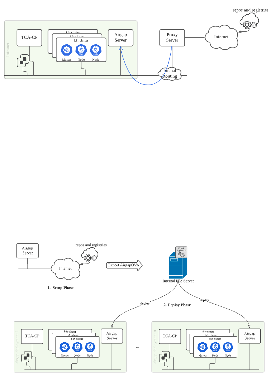
This guide lists the steps for deploying an airgap server in an environment with restricted Internet
access.
No Internet Deployment
It is not possible to build an airgap server in a pure intranet VMware Telco Cloud Automation
environment. To prepare the airgap server, you must perform the following steps:
1 Set up the airgap server on an Internet available environment.
2 Copy or move the airgap server to the target Intranet environment.
For a VM-based airgap server:
1 Export the built airgap server to an OVA, and upload it to an internal file server.
2 Import the airgap server OVA to the target no-Internet environment and configure it with the
correct networking and certificate settings.
VMware Telco Cloud Automation Deployment Guide
VMware, Inc. 85

Airgap Server Components
Internally, the airgap server contains the following components:
n Nginx daemon - Dispatches the file requests for fetching resources from the local datastore or
the Harbor server. It also provides a single HTTPS registry and Photon OS repository service
to the local VMware Telco Cloud Automation system.
n Harbor - Holds the required container images for the VMware Telco Cloud Automation system
to run. Harbor is an open source project that provides container image registry service. It
maintains all the dependent container images that are pulled from the Internet and serves the
local Kubernetes cluster container image pulling process.
n Reposync - A tool to synchronize the Photon OS packages from the Internet.
n BOM Files - Describes the container images that are BOM-dependent by the VMware Telco
Cloud Automation system.
n Scripts - Help set up the internal components of the airgap server. These scripts start the
services, load the BOM files, pull images from public registries and publishes to the local
Harbor repository on the airgap server.
VMware Telco Cloud Automation Deployment Guide
VMware, Inc. 86
Prerequisites for Setting up the Airgap Repository
To set up an airgap repository, your environment must have the prerequisites listed in this section.
Resource Preparation
To set up an airgap server, you must prepare the following resources:
1 An environment with Internet connectivity with access to the following websites:
n projects.registry.vmware.com
n vmwtec.jfrog.io
n packages.vmware.com
n github.com
2 An FQDN to assign to the airgap server. Optionally, DNS service can be available for resolving
FQDN names if the setup environment is not the target environment.
3 (Optional) Server certificates. To generate private CA-signed certificates automatically, the
VMware Telco Cloud Automation airgap server provides setup scripts. However, you can
prepare your own server certificate that is private CA-signed or public CA-signed. For a
chained certificate, it must contain all the trusted CA certificates:
n Self-signed certificate or chained certificate file.
n Certificate key file.
n (Optional) CA certificate file for verifying the server certificate. It can be a self-signed
certificate or a trusted private root CA file that has signed the certificate chain. For a
public-signed server certificate, you need not specify the CA file but ensure that you
include the CA certificates in the chained certificate file.
4 Download the airgap tarball file named VMware-Telco-Cloud-Automation-airgap-
files-2.0.0-.tar.gz from the VMware Customer Connect site. The tarball file is included in
the VMware Telco Cloud Automation build.
Deploy Photon OS 3 OVA
A virtual machine with Photon OS 3.0 Rev 3 must be available for providing repository services in
the airgap environment. Download the OVA template from here.
1 Import the OVA template onto the ESXi host in an environment that has Internet connectivity.
a Right-click the ESXi host and select Deploy OVF Template.
b To complete the deployment, follow the wizard.
2 Edit the imported airgap virtual machine with the following hardware requirements:
n CPU - 4
n RAM - 8 GB
VMware Telco Cloud Automation Deployment Guide
VMware, Inc. 87

n NIC - 1. Wire to the network with Internet connectivity.
n Hard Disks - 2. One with a minimum disk space of 16 GB for Photon OS. The other with at
least 200 GB for Docker repository, Harbor repository, and Photon repository.
Note When setting up the airgap server, The default CD drive location can display an error
while saving the settings. If you face this issue, remove the CD drive from the virtual machine.
3 Power on the airgap server.
4 Log in and update its root password. The default password is changeme.
Set up the Airgap Server
Before running the setup scripts, upload the required resources, make the airgap server
accessible to the Internet, and install the required packages for running the scripts.
Procedure
1 Upload the resources airgap tarball: After the virtual machine is powered on, set up the
eth0 network. This procedure ensures that the virtual machine is accessible from the system
downloading the airgap tarball. Set up either DHCP or a static IP address in the guest
operating system. The network settings depend on your network topology and environment
settings. Upload the tarball file to the airgap server virtual machine through a secured channel
such as the SCP command with Putty for Windows or Terminal for Linux or Mac operating
systems.
[~]$ scp VMware-Telco-Cloud-Automation-airgap-files-2.0.0-<build-number>.tar.gz
root@<airgap-server-ip>:/root/
You can now log in to the airgap server through SSH and extract the contents to its root folder.
For example:
[~]$ ssh root@<airgap server ip>
Welcome to Photon 3.0 (x86_64) - Kernel \r (\l)
root@<airgap server ip>'s password:
Last login: Fri Nov 19 06:51:50 2021 from 10.117.182.43
06:41:01 up 24 days, 6:22, 2 users, load average: 0.00, 0.00, 0.00
182 Security notice(s)
Run 'tdnf updateinfo info' to see the details.
root@photon-machine [ ~ ]# ls
VMware-Telco-Cloud-Automation-airgap-files-2.0.0-<build-number>.tar.gz
root@photon-machine [ ~ ]# tar xfz VMware-Telco-Cloud-Automation-airgap-files-2.0.0-<build-
number>.tar.gz
VMware Telco Cloud Automation Deployment Guide
VMware, Inc. 88

root@photon-machine [ ~ ]# ls
VMware-Telco-Cloud-Automation-airgap-files-2.0.0-<build-number>.tar.gz airgap
root@photon-machine [ ~ ]# ls airgap
bom scripts
Note If you are setting up the airgap server on both VMware Telco Cloud Automation
version 1.9.5 and version 2.0.0, then download the 1.9.5 airgap BOM tarball from the VMware
Customer Connect site. Upload, extract, and copy the BOM files into the target BOM folder.
The BOM folder contains all the BOM files for describing the container images. The Scripts
folder contains scripts used for setting up and deploying the airgap server.
Certificates: (Optional) If you use your own certificate, upload its relevant files into the /
roots/certs folder. You can also use scripts for generating the certificate at runtime.
2 Set up the network for Internet.
Ensure that your airgap virtual machine is accessible to the Internet. If you use a proxy server,
run the following script:
root@photon-machine [ ~ ]# . airgap/scripts/bin/setup-proxy.sh <proxy-sever-url> <airgap-
server-fqdn>,<local-subnet>
For example:
root@photon-machine [ ~ ]# . airgap/scripts/bin/setup-proxy.sh http://
proxy.example.com:8118 ag-tmp.example.com,192.168.0.0/24
The script contains two parameters:
n proxy-sever-url - The proxy server URL.
n airgap-server-fqdn, local-subnet - Comma-separated exclusion list of networks for
bypassing proxy.
Note To avoid Harbor image publishing failure, ensure that airgap server FQDN and local
network are added to the no_proxy list.
If your environment uses other approaches to access the Internet, configure your network
infrastructure to ensure that Internet is accessible.
To verify that the airgap virtual machine can access the required Internet resources, run the
following commands:
curl https://projects.registry.vmware.com --head
curl https://vmwtec.jfrog.io --head
curl https://packages.vmware.com --head
curl https://github.com --head
These commands must return 200 OK, which ensures that your network is ready.
VMware Telco Cloud Automation Deployment Guide
VMware, Inc. 89

3 Install Ansible Playbook.
root@photon-machine [ ~ ]#tdnf update
root@photon-machine [ ~ ]#tdnf install ansible.noarch -y
If Ansible Playbook fails to install, verify whether the airgap server can access the Internet.
4 Prepare the user-inputs.yml file.
Set the airgap server up as a template and then deploy a customized airgap server
using this template. The setup YAML files are available at airgap/scripts/vars/. The
airgap/scripts/vars/user-inputs.yml file contains user-defined variables that specify
the parameters for setting up the airgap server. Two examples are provided in the vars folder
for this purpose. Use the
setup-user-inputs.yml as a template and add your variables.
root@photon-machine [ ~/airgap/scripts/vars ]# ls
deploy-user-inputs.yml setup-user-inputs.yml
root@photon-machine [ ~/airgap/scripts/vars ]# cp setup-user-inputs.yml user-inputs.yml
root@photon-machine [ ~/airgap/scripts/vars ]# vi user-inputs.yml
The user-inputs.yml file contains input parameter descriptions. You can change these
values according to your environment.
5 Run the setup.yml Ansible Playbook.
root@photon-machine [ ~/airgap ]# ansible-playbook scripts/setup.yml > ansible.log 2>&1 &
root@photon-machine [ ~/airgap ]# tail -f ansible.log
Ansible Playbook takes around three hours to run, depending on your network speed, and
you can view the log file to monitor progress. If there is an error, run Ansible Playbook again
with the same command.
Export the Airgap Server Virtual Appliance
To deploy your airgap server virtual machine in multiple airgap environments, export it as a virtual
appliance and upload it to the local file server.
For steps to export a virtual machine to OVA format, see the
VMware vSphere Product
Documentation
here.
After generating the OVA, upload it to the local file server for the airgap deployments.
Deploy Airgap Servers from the Airgap OVA
After uploading the airgap server OVA to the local file server, deploy the airgap server in the
VMware Telco Cloud Automation environment.
VMware Telco Cloud Automation Deployment Guide
VMware, Inc. 90

Prerequisites
To use the airgap server in the VMware Telco Cloud Automation system, you must configure
a DNS server for resolving the airgap server domain name. This DNS server is useful when
deploying VMware Tanzu Kubernetes clusters.
Procedure
1 Use the OVA that you imported into the local file system and deploy the airgap server virtual
machine on the target Internet-restricted environment.
2 Power on the virtual machine and log into it.
3 To prepare the system for the target environment, define the environment-related parameters
in the user-input.yml file and run the Ansible Playbook. In the deploy phase, use
the deploy-user-inputs.yml as a template for storing customization parameters. The
customization parameters include:
n Network adapter IP address.
n FQDN of the airgap server.
n Certificate updates.
n Clear unused settings such as proxy.
root@photon-machine [ ~/airgap/scripts/vars ]# ls
deploy-user-inputs.yml setup-user-inputs.yml
root@photon-machine [ ~/airgap/scripts/vars ]# cp deploy-user-inputs.yml user-inputs.yml
root@photon-machine [ ~/airgap/scripts/vars ]# vi user-inputs.yml
The deploy-user-inputs.yml file at scripts/vars provides an example of the required
inputs in the deployment phase. You can copy it to your user-inputs.yml file and modify
according to your environment requirement.
4 To customize the airgap server, run the deploy.yml file.
root@photon-machine [ ~/airgap ]# ansible-playbook scripts/deploy.yml > ansible.log 2>&1 &
root@photon-machine [ ~/airgap ]# tail -f ansible.log
Results
You can lose connection if Ansible Playbook changes the IP address on eth0. If you lose
connection, log back in and verify the ansible.log file for changes. During deployment, the
airgap server does not synchronize its repository from the Internet. Hence, it takes only a few
minutes for completing the customizations.
VMware Telco Cloud Automation Deployment Guide
VMware, Inc. 91
Build an Airgap Server for Upgrading VMware Telco Cloud
Automation
To upgrade to a later version of VMware Telco Cloud Automation, build a brand new airgap server
for hosting the images and packages of the existing version and the target version.
Prerequisites
Build a new airgap server when:
1 You cannot move the existing airgap server to an Internet accessible network.
2 You have set up the existing airgap server with VMware Telco Cloud Automation version 1.9.5.
Procedure
1 Deploy a new Photon OS OVA. For more information, see Prerequisites for Setting up the
Airgap Repository.
VMware Telco Cloud Automation Deployment Guide
VMware, Inc. 92

2 To set up the airgap server, follow the steps 1 to 3 listed in Set up the Airgap Server and
perform the following modifications:
a Download the existing VMware Telco Cloud Automation file bundle from the VMware
Customer Connect site. The following table lists the file name according to the version of
VMware Telco Cloud Automation.
Version File Name
1.9.5 VMware-Telco-Cloud-Automation-airgap-
files-1.9.5<.x>-.tar.gz
2.0 VMware-Telco-Cloud-Automation-airgap-
files-2.0.0-.tar.gz
b Copy the downloaded airgap server bundle to the new airgap server, and extract its local
BOMs to the airgap BOM folder.
For VMware Telco Cloud Automation 1.9.5:
[~]$ scp VMware-Telco-Cloud-Automation-airgap-files-1.9.5.x-<build-number>.tar.gz
root@<airgap-server-ip>:/root/
On the airgap server:
root@photon-machine [ ~ ]# tar vxf VMware-Telco-Cloud-Automation-airgap-files-1.9.5.x-
<build-number>.tar.gz
root@photon-machine [ ~ ]# ls bom/
airgap-extra-1.9.5.x-<build-number>.yaml tkg-bom-v1.3.1-patch1.yaml
k8sbootstrapper-airgap-1.9.5.x-<build-number>.yaml tkr-bom-v1.20.5+vmware.2-tkg.1.yaml
root@photon-machine [ ~ ]# cp bom/k8sbootstrapper-airgap-1.9.5.x-<build-number>.yaml
airgap/bom/
root@photon-machine [ ~ ]# cp bom/airgap-extra-1.9.5.x-<build-number>.yaml airgap/bom
For VMware Telco Cloud Automation 2.0:
[~]# scp VMware-Telco-Cloud-Automation-airgap-files-2.0.0-<build-number>.tar.gz
root@<airgap-server-ip>:/root/
on the airgap server:
root@photon-machine [ ~ ]# tar vxfz VMware-Telco-Cloud-Automation-airgap-files-2.0.0-
<build-number>.tar.gz airgap/bom/
VMware Telco Cloud Automation Deployment Guide
VMware, Inc. 93

c Perform step 4 as listed in Set up the Airgap Server. When defining the user input, specify
multiple upgrade versions of VMware Telco Cloud Automation in the tca_versions field.
root@photon-machine [ ~ ]# cd airgap/scripts/vars
root@photon-machine [ ~/airgap/scripts/vars ]# ls
deploy-user-inputs.yml setup-user-inputs.yml
root@photon-machine [ ~/airgap/scripts/vars ]# cp setup-user-inputs.yml user-inputs.yml
root@photon-machine [ ~/airgap/scripts/vars ]# vi user-inputs.yml
# 1. General Configurations
# tca_versions: TCA versions this airgap server to serve for, values "1.9.5",
# "2.0.0", "2.0.1" or "1.9.5+2.0.0+2.0.1"
# server_fqdn: airgap server domain name
# root: root folder for the ansible runtime output files
tca_versions: 1.9.5+2.0.0+2.0.1
d Complete the remaining steps listed in Set up the Airgap Server.
3 Export the airgap server virtual appliance. For more information, see the
VMware vSphere
Product Documentation
here.
4 To replace the existing airgap server with the new one, perform the following steps:
a Move the existing airgap server to the offline mode.
b Deploy the new airgap server using steps listed in Deploy Airgap Servers from the Airgap
OVA. Use the same IP address, FQDN, and connect it to the same network as the previous
airgap server.
Validate Airgap Server Setup
After setting up the airgap server, validate it. Ansible Playbook performs these validations
automatically, but you can also run them manually.
Procedure
1 Validate the TDNF version and the makecache function.
The reposync function is available from TDNF version 3.1.0 onwards, so install the latest TDNS
version. To ensure that the TDNF function works correctly, create a cache:
tdnf --version
tdnf clean all
tdnf makecache
Note If you encounter an error or a permission issue when running TDNF, remove the lock
file at /var/run/.tdnf-instance-lockfile and try again.
VMware Telco Cloud Automation Deployment Guide
VMware, Inc. 94

2 Validate certificate availability.
Verify that the certificates are copied to /etc/docker/certs.d/{airgap server fqdn}:[{https
port number}]. When using custom certificates, the certs folder name is the same as the
airgap server FQDN and the HTTPS port number is optional. When using system-generated
certificates, you must create the certs folder with the HTTPS port number.
ls /etc/docker/certs.d/{airgap server fqdn}:[{https port number}]
3 Validate Harbor login and image pulling.
Verify if you can log in to Harbor and pull an image from it.
docker login {airgap server fqdn}/registry
docker pull {airgap server fqdn}/registry/tkr-compatibility:v1
4 Validate if the nginx service is running.
nginx -T
systemctl status nginx
5 Validate Photon OS repositories.
Verify if you can access the four repositories that are used during cluster creation:
curl -k -I "https://$server_fqdn/updates/photon-updates/" 2>&1
curl -k -I "https://$server_fqdn/release/photon/" 2>&1
curl -k -I "https://$server_fqdn/updates/photon-telco-updates/" 2>&1
curl -k -I "https://$server_fqdn/updates/photon-telco-debuginfo/" 2>&1
6 Validate the Kubernetes images sync list.
If you encounter a failure, view the /root/logs/publish-image.log file for a summary of
image sync statistics and image list.
Upgrade Repositories on the Airgap Server
You can incrementally upgrade the Harbor and Photon OS repositories on the airgap server host
without rebuilding and redeploying the entire server.
Prerequisites
To upgrade the repositories, connect the airgap server to the Internet.
Procedure
1 Download the latest airgap TAR file from VMware Customer Connect.
You must upgrade your airgap Harbor repository after you upgrade to a newer version of
VMware Telco Cloud Automation. Download the airgap TAR file from the VMware Customer
Connect site, the same location where you downloaded the newer build of VMware Telco
Cloud Automation, and copy it to the /root folder.
VMware Telco Cloud Automation Deployment Guide
VMware, Inc. 95

2 Extract the airgap TAR file and update the user-inputs.yml file.
a Extract the airgap TAR file:
tar xvfz VMware-Telco-Cloud-Automation-airgap-files-2.0.0-<build number>.tar.gz
cd airgap/scripts
b Update user-inputs.yml.
cp vars/setup-user-inputs.yml vars/user-inputs.yml
c Use an editor to open the YAML file:
vi vars/user-inputs.yml
d In the editor, set the server_fqdn parameter to your airgap server FQDN name:
server_fqdn: myairgap.example.com
e Save the file and close the editor. Before running the Ansible Playbook, create the logs
folder:
mkdir -p /root/airgap/logs
touch /root/airgap/logs/publish-image.log
3 Perform the repository upgrade. This step incrementally upgrades Harbor and Photon OS
repositories on the server.
ansible-playbook playbooks/setup-repo.yml 2>&1 > upgrade_repo.log &
To monitor the output in realtime, view the repository upgrade log file, and view the Harbor
image sync log file:
tail -f upgrade_repo.log
tail -f /root/airgap/logs/publish-image.log
Upgrade Existing Airgap Servers
The VMware Telco Cloud Automation airgap solution does not support inline upgrading of airgap
servers that are running on versions prior to 2.0. To upgrade these versions to a newer version,
deploy a new airgap server that contains the images and packages of both the existing version and
the target version.
Performing an inline upgrade for airgap servers running on VMware
Telco Cloud Automation 2.0
To perform an inline upgrade, see Inline Upgrade: Synchronize Packages and Images of a New
VMware Telco Cloud Automation Build.
VMware Telco Cloud Automation Deployment Guide
VMware, Inc. 96

Inline Upgrade: Synchronize Packages and Images of a New VMware
Telco Cloud Automation Build
Using this method, you can upgrade an airgap server running on VMware Telco Cloud Automation
2.0 airgap scripts to a later version.
Prerequisites
n Move and connect your airgap server to a network with Internet access.
n After upgrading VMware Telco Cloud Automation to a newer version, Upgrade your airgap
Harbor repository.
Procedure
1 Download the airgap TAR package from the newer VMware Telco Cloud Automation build.
2 Extract the airgap file and update the user-inputs.yml file.
a To extract the airgap file:
root@photon-machine [ ~ ]# tar xvfz VMware-Telco-Cloud-Automation-airgap-files-2.0.1-
<build number>.tar.gz
cd airgap/scripts
b Back up the existing user-inputs.yml file.
c Update the user-inputs.yml file with tca_versions: 1.9.5+2.0.0+2.0.1. Make other
necessary changes similar to the previous user-inputs.yml file.
d Ensure that the FQDN address and other settings are similar to the backup
user_inputs.yml file.
For example:
root@photon-machine [ ~ ]# cd airgap/scripts/vars
root@photon-machine [ ~/airgap/scripts/vars ]# ls
deploy-user-inputs.yml setup-user-inputs.yml user-inputs.yml
root@photon-machine [ ~/airgap/scripts/vars ]# mv user-inputs.yml user-inputs.yml.bak
root@photon-machine [ ~/airgap/scripts/vars ]# cp setup-user-inputs.yml user-inputs.yml
root@photon-machine [ ~/airgap/scripts/vars ]# vi user-inputs.yml
# 1. General Configurations
# tca_versions: TCA versions this airgap server to serve for, values "1.9.5",
# "2.0.0", "2.0.1" or "1.9.5+2.0.0+2.0.1"
# server_fqdn: airgap server domain name
# root: root folder for the ansible runtime output files
tca_versions: 1.9.5+2.0.0+2.0.1
server_fqdn: <same with the previous server_fqdn setting>
VMware Telco Cloud Automation Deployment Guide
VMware, Inc. 97

e Save the file and exit the editor.
f Before running Ansible Playbook, create a log folder if it does not exist.
root@photon-machine [ ~ ]# mkdir -p /root/airgap/logs
root@photon-machine [ ~ ]# touch /root/airgap/logs/publish-image.log
3 Perform a repository upgrade:
root@photon-machine [ ~/airgap ]# ansible-playbook scripts/playbooks/setup-repo.yml 2>&1
>> upgrade_repo.log &
root@photon-machine [ ~/airgap ]# disown
This step will incrementally upgrade Harbor and Photon repositories on the server.
To view the real-time output, you can monitor the repository upgrade log file and the Harbor
image sync log file.
root@photon-machine [ ~/airgap ]# tail -f upgrade_repo.log
root@photon-machine [ ~/airgap ]# tail -f /root/airgap/logs/publish-image.log
4 After Ansible Playbook completes running, disconnect from the Internet and move back to the
airgap environment.
Results
You have successfully performed an inline upgrade.
What to do next
Validate the airgap server setup. For more information, see Validate Airgap Server Setup.
Troubleshooting Airgap Server Setup
If you encounter problems when setting up the airgap server, you can use a troubleshooting topic
to understand and solve the problem, if there is a workaround.
Error When Creating Repository
When using the createrepo command, you can encounter the following error message /path/to/
repo/.repodata/ already exists!. This issue can occur in the build metadata of the Photon OS
repository, after all the packages are synchronized to the local system. The createrepo command
checks for a temp folder named .repodata under the repo folder. If there is an existing .repodata
folder, the system assumes that the createrepo session is running and exits.
Workaround: Remove the .repodata folder and retry.
1 View the ansible.log or upgrade_repo.log files for errors.
VMware Telco Cloud Automation Deployment Guide
VMware, Inc. 98

2 View the folders that report errors. For example, if the error is found in /photon-reps/
updates/photon-updates/.repodata/, list them in the parent folder:
ls -lta /photon-reps/updates/photon-updates/
3
Remove the existing .repodata folder and all the contents in it.
rm -rf /photon-reps/updates/photon-updates/.repodata/
4 Rerun the setup or upgrade process:
ansible-playbook scripts/setup.yml > ansible.log 2>&1 &
or
ansible-playbook playbooks/setup-repo.yml 2>&1 > upgrade_repo.log &
VMware Telco Cloud Automation Deployment Guide
VMware, Inc. 99
Upgrading the Airgap Server and
High Availability
10
To upgrade VMware Telco Cloud Automation in an airgap environment, the airgap server must
host all the dependent images and packages of the target version and the current version. To
upgrade the airgap server in VMware Telco Cloud Automation version 2.0, replace the existing
airgap server virtual machine with a new one that contains the current and target version images
and packages.
Ensure that the new airgap server contains the same domain name as the existing one. Also,
VMware Telco Cloud Automation must be able to verify the certificates of the new airgap server
without updating the CA certificates configured on the clusters.
Replacing the air-gap server impacts the following activities on VMware Telco Cloud Automation:
n Cluster creation.
n Management Cluster deletion.
n Node Pool creation.
n Cluster scale out.
n CNF instantiation.
During replacement, pulling images for these activities can fail as the connection is broken or the
airgap server IP is unreachable temporarily. Kubernetes reconciles these failures after you replace
the airgap server.
To avoid this temporary impact, you can adopt a high availability (HA) architecture for the airgap
server. Deploy multiple airgap servers and expose a single virtual server through a third party
load balancer. You can set the virtual server as HTTPS offloading or HTTPS passthrough. HTTPS
offloading stops the SSL connection and HTTPS passthrough stops the TCP connection. If there
is no requirement to inspect or manipulate the http-level signatures of the airgap server image,
package, and Helm charts downloading traffic, configure load balancer with HTTPS passthrough.
With load balancer, you can scale out the airgap servers for performance on demand, without
interrupting its service. To upgrade the airgap server using a load balancer, leverage the load
balancer Server Pool Management feature:
1 Add the new airgap server virtual machine that contains the images, Helm charts, and
packages into the load balancer airgap server pool.
VMware, Inc.
100
2 In the load balancer configuration, deactivate the existing airgap server by changing its state
to Disabled. The load balancer server does not schedule any new requests to the deactivated
server. However, it continues to process existing HTTP requests.
3 Remove the previous version of the airgap server from the load balancer server pool and
delete the airgap server virtual machine.
VMware Telco Cloud Automation Deployment Guide
VMware, Inc. 101

Managing System Settings
11
Use the appliance management interface for viewing, configuring, and managing system-level
functions.
The appliance management interface is reached by navigating to the management port: https://
tca-ip-or-fqdn:9443. This interface uses the system administration credentials set up during the
OVA deployment.
The appliance management interface provides access to the system Dashboard, Appliance
Summary, Configuration, and Administration information.
Note VMware Telco Cloud Automation Manager deployed in HA mode does not support editing
NTP settings, syslog servers, DNS, and performing upgrades.
This chapter includes the following topics:
n Network Ports and Protocols
n Understanding the Appliance Management Dashboard
n Updating the Time Settings
n Updating the System Name
n Managing CA and Self-Signed Certificates
n Update Server Certificate
n Reboot an Appliance
n Change Appliance Password
n Update License Key
n Backing Up and Restoring the System
n Technical Support Logs
n Upgrading Standalone VMware Telco Cloud Automation Appliances
Network Ports and Protocols
To enable connections between devices, configure these ports in your environment.
VMware, Inc.
102

Activation and Service Updates
This table lists the required connections for activation, publishing system updates, and enhanced
support.
The perimeter firewall controlling internet-bound traffic must be configured to allow the following
connections.
Source Destination Service Purpose
TCA-CP n connect.tec.vmware.co
m
n hybridity-
depot.vmware.com
TCP-443 n Activation and
entitlement.
n Access to published
TCA-CP updates.
VMware Telco Cloud
Automation Manager
n connect.tec.vmware.co
m
n hybridity-
depot.vmware.com
TCP-443 n Activation and
entitlement.
n Access to published
VMware Telco Cloud
Automation Control
Plane updates.
VMware Telco Cloud
Automation Manager
TCA-CP TCP-443 VIM configuration and
management.
TCA-CP Connections
Allow these connections between TCA-CP and the local VIM environment.
Source
Destination Service Purpose
TCA-CP vCenter Server TCP-443 vSphere SSO Lookup Service
TCA-CP ESXi host TCP-443
TCA-CP NSX Manager TCP-443 NSX API
TCA-CP VMware Cloud Director TCP-443 vCD API access
TCA-CP AMQP/RabbitMQ Broker TCP-5671/5672 Advanced Message Queue
Protocol (SSL or non-SSL
notifications)
TCA-CP vRealize Orchestrator TCP-8281 vRealize Orchestrator
integrations
Web Portal TCA-CP TCP-443 VMware Telco Cloud
Automation UI
Web Portal TCA-CP TCP-9443 VMware Telco Cloud
Automation UI
Telco Cloud Automation Environment Connections
Allow these connections between VMware Telco Cloud Automation and local environments.
VMware Telco Cloud Automation Deployment Guide
VMware, Inc. 103

Source Destination Service Purpose
VMware Telco Cloud
Automation
vCenter Server TCP-443, TCP-7444 vSphere SSO Lookup Service
VMware Telco Cloud
Automation
SVNFM TCP-443 SVNFM integration
Web portal VMware Telco Cloud
Automation
TCP-443 VMware Telco Cloud
Management service UI
Web portal VMware Telco Cloud
Automation
TCP-9443 Telco Cloud Management
appliance management UI
Management Services Connections
The perimeter firewall controlling internet-bound traffic must be configured to allow the following
connections.
Source Destination Service Purpose
TCA-CP DNS Server TCP-53 Name services
TCA-CP NTP Server TCP-123 Synchronized time
TCA-CP DNS Server TCP-53 Name services
TCA-CP NTP Server TCP-123 Synchronized time
Understanding the Appliance Management Dashboard
The system Dashboard provides access to status and services, configuration settings, and system-
level administration tasks.
The Dashboard is the first screen that appears after you log in to the appliance management
interface port (:9443). It provides access to various system management settings through a set of
tabs at the top of the display.
VMware Telco Cloud Automation Deployment Guide
VMware, Inc. 104

Dashboard Tab Description
Dashboard Displays the appliance status as a set of summary panels:
n System information and resource use
n NSX status
n vCenter status
n SSO status
n Public Access URL status
The panels visible in the display depend on the VMware
Telco Cloud Automation Control Plane installation type. To
change the configuration settings for a panel, click Manage.
The system redirects you to the Configuration tab, where
you can update the settings.
Appliance Summary Displays the status of services running on the system:
n Hybridity Services
n Common Services
n System Level Services
Options are provided to stop and restart services. The list of
services in the display varies based on the installation type.
VMware Telco Cloud Automation Deployment Guide
VMware, Inc. 105

Dashboard Tab Description
Configuration Displays the list of service configuration settings.
n Licensing
n vCenter
n vRealize Orchestrator
n SSO
n Public Access URL
n vSphere Role Mapping
n Data center location
To display the current settings, click an item in the list. To
modify the current settings, click Edit.
Administration Displays the list of system-level configuration settings.
n General Settings
n Time Settings
n Syslog Server
n System Name
n Network Settings
n General Network
n DNS Servers
n Proxy
n Static Routes
n Troubleshooting
n Technical Support
n Logs
n Upgrade
n Back up & Restore
n Certificate
n Trusted CA Certificate
n Server Certificate
To display or edit the settings, click an item.
Updating the Time Settings
The system provides initial NTP Server settings during the OVA deployment in the vCenter Server.
These settings can be updated in the appliance management interface.
Caution Editing NTP Settings requires restarting the Appliance Management Service. You can
restart this service from within the Appliance Summary tab.
Editing and Removing the NTP Server Configuration
NTP Settings can be modified in the appliance management interface.
VMware Telco Cloud Automation Control Plane (TCA-CP) requires a valid NTP server
synchronized time for integrated systems operations.
1 Navigate to the appliance management interface: https://tca-cp-or-fqdn:9443.
VMware Telco Cloud Automation Deployment Guide
VMware, Inc. 106

2 Navigate to the Administration tab.
3 Select Time Settings on the side menu, click Edit (or Unconfigure NTP Servers).
4 Enter the NTP server.
Multiple servers can be specified using a separated comma-separated list.
5 Navigate to the Appliance Summary tab in the dashboard, locate the Appliance Management
Service, and click Restart.
Note This option is not available in an HA-based deployment.
Updating the System Name
The initial Hostname is provided during the OVA deployment. The system name can be updated in
the Appliance Management interface.
Editing the System Name
1 Navigate to the Appliance Management interface https://tca-cp-ip-or-fqdn:9443.
2 Navigate to the Administration tab.
3 Select System Name on the side menu, then click Edit.
4 Enter the System Name. Click Save.
Managing CA and Self-Signed Certificates
Use the appliance management interface for adding or removing certificates from the system
certificate store.
Importing Certificates with a Remote Site URL
To pair the sites when the remote system uses self-signed certificates, perform the following steps:
1 Navigate to the appliance management interface https://tca-cp-ip-or-fqdn:9443.
2 Navigate to the Administration tab.
3 Select Certificate > Trusted CA Certificate on the side menu.
4 Click Import and select the URL option.
5 Enter the URL for the target system.
Update Server Certificate
After deploying VMware Telco Cloud Automation, it is recommended to update its server
certificate. From the Update Server Certificate screen of the Appliance Manager user interface,
VMware Telco Cloud Automation Deployment Guide
VMware, Inc. 107

you can update the Web server certificate or the Appliance Management server certificate and
private key.
Prerequisites
If you have a chained CA-signed certificate or a chained self-signed certificate, you must combine
the certificates in the chain and keep them in the Privacy Enhanced Mail (PEM) format. Instructions
for generating certificates are not covered in this guide.
Note By default, server certificates available for Web and Appliance Management are self-signed
certificates.
Procedure
1 Log in to the Appliance Manager user interface https://tca-cp-ip-or-fqdn:9443.
2 Navigate to the Administration tab.
3 From the left navigation menu, select Certificate > Server Certificate.
The Update Server Certificate screen is displayed.
4 From the Select Service drop-down menu, select the endpoint for which you want to update
the server certificate. Select either Web certificate or Appliance Management.
5 In the Server Certificate text box, paste the certificate in PEM format.
6 In the Private Key text box, paste the private key in PEM format.
7 Click Apply.
Results
Services hosting the certificates restart automatically.
What to do next
n For the updated certificate take effect, log out of the Appliance Manager user interface and log
back in.
n For a seamless connectivity, keep updating the server certificate before it expires.
Reboot an Appliance
You can reboot an appliance from the Appliance Management user interface.
Note This option is not available for HA-based VMware Telco Cloud Automation deployments.
Procedure
1 Navigate to the appliance management interface https://tca-cp-ip-or-fqdn:9443.
2 From the top-right corner of the screen, click Admin > Reboot.
3 From the confirmation screen, click Reboot.
VMware Telco Cloud Automation Deployment Guide
VMware, Inc. 108
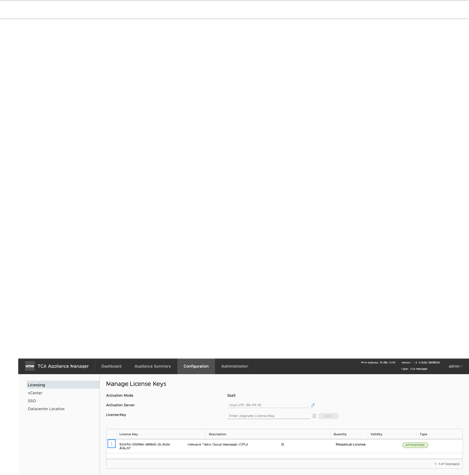
Results
The appliance reboots.
Change Appliance Password
You can update the admin user password using the Appliance Management user interface.
Note This option is not available for HA-based VMware Telco Cloud Automation deployments.
Procedure
1 Navigate to the appliance management interface https://tca-cp-ip-or-fqdn:9443.
2 From the top-right corner of the screen, click Admin > Change Password.
3 In the Change Password screen, enter the new password and confirm it.
4 Click Update.
You are logged out of the Appliance Management user interface. Log in again using your new
password.
Update License Key
You can update the license key in the Appliance Management interface.
Procedure
1 Navigate to the Appliance Management interface https://tca-cp-ip-or-fqdn:9443.
2 Navigate to the Configuration tab.
3 Select Licensing on the side menu.
4 In the Managing License Keys page, click the Option button (⋮) against the current activation
license, and click Edit.
VMware Telco Cloud Automation Deployment Guide
VMware, Inc. 109

5 Enter the license key and click OK.
Results
Your appliance license key is updated.
Backing Up and Restoring the System
You can back up and restore the appliance from the appliance management interface.
Backup and restore operations are available in the TCA Appliance Manager interface except when
restricted by a cloud service provider.
Using the TCA Appliance Manager interface, you can:
n Generate a backup of the VMware Telco Cloud Automation Manager and VMware Telco Cloud
Automation Control Plane (TCA-CP)
n Use the backup file to restore to a healthy system.
n Schedule a backup operation on an hourly, daily, or weekly frequency or generate a backup
manually.
n Upload the backup file to an SFTP or FTP server.
n Download the backup file to your local machine.
Backing Up VMware Telco Cloud Automation Control Plane
You use the appliance management interface to create a backup file.
This operation backs up the following information:
n Inventory data
n Configuration files
n Certificates
n System UUID
The backup file is saved in the tar.gz format.
VMware Telco Cloud Automation Deployment Guide
VMware, Inc. 110

Procedure
1 Log in to the appliance management interface: <https://tca-cp-ip-or-fqdn:9443>.
2 Navigate to Administration > Troubleshooting > Backup & Restore.
3 (Optional) Set up an FTP server for uploading the backup file:
a Click the FTP server setting tab.
b Click Add.
Note The best practice to use a Linux-based OpenSSH host for file transfer operations.
c Enter the FTP server information and click Save.
Note Ensure that the backup directory path you provide is unique for every VMware Telco
Cloud Automation appliance instance.
4 (Optional) Configure a backup schedule:
Note The best practice is to schedule Daily backups. Restoring from backup files that are
more than two days old is not supported due to potential inventory changes from the backup
time to present.
a Click the Scheduling tab.
b Click Add.
The scheduling window appears.
c Select the Backup Frequency.
d Enter the hour and minute of the backup.
e Click Save.
5 Click the Backup and Restore tab.
6 Click Generate.
If a backup schedule is configured, the system creates the backup file at the scheduled time.
7 For manual backups, save the backup file:
Note If you have scheduled backups, the system automatically generates the backup file at
the scheduled time and saves the file to the FTP server.
u To save the generated file to an FTP server, select the box Upload to server .
u To download the generated file to the client browsing system, click Download.
VMware Telco Cloud Automation Deployment Guide
VMware, Inc. 111

Restoring the System
You use the appliance management interface to restore the system from a backup file. The restore
operation is used in cases where the system has become corrupt or unusable due to resource or
system failures.
This operation restores the appliance to the state it was in at the time of the backup. The contents
of the backup file supersede configuration changes made before restoring the appliance.
Prerequisites
You have deployed a replacement system that is clean of prior configuration settings. The
replacement system has the same software version and IP address as the original system.
Note A clean system deployment requires only the minimum configuration to be manageable and
that the system is network reachable from the operator or client system.
Procedure
1 Log in to the appliance management interface: https://tca-cp-ip-or-fqdn:9443.
2 Navigate to Administration > Troubleshooting > Backup & Restore.
3 If backup files stored in a SFTP or an FTP server, the list is displayed under Restore.
4 Select the backup file to restore and click Restore.
5 If you have stored the backup file in a local repository, click Choose File, browse to the backup
file, and open it.
Note Restoring from backup files that are more than two days old is not supported.
6 Click Continue.
The system verifies the uploaded file.
7 Click Restore.
The restoration begins. This process can take several minutes to complete.
8 Verify that the system is operating properly:
a Navigate to the Dashboard tab and confirm that the component status is green.
b Navigate to the Appliance Summary tab and ensure that the Hybridity Services, Common
Services, and System Level Services are running.
Restoring the Appliance
Using the backup files, you can restore VMware Telco Cloud Automation Manager or VMware
Telco Cloud Automation Control Plane (TCA-CP) to the state of the provided backup. To perform
this operation, deploy the OVA of the appliance in the vSphere Client and log in to the Appliance
Management console.
VMware Telco Cloud Automation Deployment Guide
VMware, Inc. 112
After deploying the OVA and logging in to the Appliance Management console, the role selection
screen is displayed. In this example, we list the steps to restore the VMware Telco Cloud
Automation Manager appliance.
Prerequisites
n You must have saved a backup file of the VMware Telco Cloud Automation in the tar.gz
format.
n Before restoring an appliance, ensure that the virtual machine running its previous instance is
powered down.
Procedure
1 In the role selection screen, select Telco Cloud Automation - Manager.
2 In the Activate your Telco Cloud Automation instance screen, click Restore.
The Backup and Restore screen is displayed.
3 Select and upload the VMware Telco Cloud Automation Manager backup tar.gz file. Click
Choose File.
4 Click Continue.
The backup file is uploaded to the Appliance Manager.
5 Click Restore.
Results
The restore operation restores the database, configuration files, certificates, and network settings
of the appliance to the settings in the tar.gz file.
Technical Support Logs
If VMware Telco Cloud Automation does not run as expected, you can collect the relevant logs for
requesting technical support.
You can collect the following types of logs:
n Crash logs.
n MongoDB dump.
VMware Telco Cloud Automation Deployment Guide
VMware, Inc. 113

n Kubernetes Cluster logs.
Note
n Collect Workload cluster logs from the VMware Telco Cloud Automation Control Plane where
you have deployed its corresponding Management cluster.
n The time taken to collect Kubernetes Cluster logs depends on the number of objects within the
clusters.
n You can collect the logs of up to five Management clusters at a time.
Procedure
1 Log in to the appliance management interface: https://tca-cp-or-fqdn:9443.
2 Navigate to Troubleshooting > Technical Support Logs.
3 Select the logs.
4 For Kubernetes Cluster logs, select the Management cluster logs from the table. You can
select up to five Management clusters.
5 Click Request.
Upgrading Standalone VMware Telco Cloud Automation
Appliances
You can manually upgrade the VMware Telco Cloud Automation appliances that are activated in
the Standalone mode.
Procedure
1 Go to the
VMware Customer Connect
site at my.vmware.com, download the VMware Telco
Cloud Automation upgrade bundle.
2 Save the upgrade bundle in a jump host that can access the appliance to be upgraded.
3 Navigate to the Appliance Management interface https://tca-cp-ip-or-fqdn:9443.
4 Click the Administration tab and select Upgrade.
5 Details of the current installed version, upgrade date, and upgrade state are displayed. Click
Upgrade.
6 To upgrade to a newer version, click Browse and upload the upgrade bundle.
7 Click Continue.
VMware Telco Cloud Automation Deployment Guide
VMware, Inc. 114

Results
The appliance upgrades to the newer version.
Note The Upgrade option is not available for HA-based VMware Telco Cloud Automation
deployments.
VMware Telco Cloud Automation Deployment Guide
VMware, Inc. 115

Troubleshooting Deployment
12
Deployment troubleshooting information.
This chapter includes the following topics:
n Troubleshooting Deployment Scripts
n Infrastructure Automation Troubleshooting
n General Troubleshooting
Troubleshooting Deployment Scripts
Troubleshooting tips for day 0 deployment scripts.
SSH Keys
The SSH public and private key pair files in a configuration input file such as bootstrapper.json
is the absolute path to the file. For example:
"sshPrivateKeyFile":"/home/admin/.ssh/id_rsa",
"sshPublicKeyFile":"/home/admin/.ssh/id_rsa.pub"
Note To generate the SSH key pair files for the first time, use the ssh-keygen utility.
Base64 Password Encryption
When generating password using a base64 tool, ensure that the echo command does not include
a new line. For example, echo "<password_to_be_encoded>" | base64 does not work since
"<password_to_be_encoded>" | base64 represents a new line.
To avoid emitting a new line, use -n in the echo command. For example, echo -n
"<password_to_be_encoded>" | base64.
Remove or Comment Out Unwanted Overrides From the
Configuration Input JSON File
When you use a template configuration file, there can be keys that are not relevant to your
configuration. You must disable these keys either by commenting them out or removing them
altogether.
VMware, Inc.
116

For removing a key from the overrideValues section, simply delete the line from the configuration
input JSON template.
You can comment it out by prefixing comment_ to the key, such as
comment_<key_to_be_commented>.
For example, to comment out airgap related keys, rename the keys as:
"_comment_airgapFQDN": ...
"_comment_airgapCaCert": ...
To remove vrliAddress from the configuration, delete the line and ensure that there is no key
called vrliAddress defined in the overrideValues section.
No Conflict with Static IP
Since multiple static IP addresses are used during day 0 deployment, ensure that the IP addresses
are not used on the same network. Otherwise, access to the UI or platform service can fail. Static
IP addresses are used for:
"controlPlaneEndpointIP" for "managementCluster"
"controlPlaneEndpointIP" for "workloadCluster"
"ip" for "tcaMgr"
"ip for "tcaCp"
Infrastructure Automation Troubleshooting
Troubleshooting procedure for infrastructure automation.
Cluster Creation Failure
The following can cause cluster creation failure:
n etcdserver leader change.
n etcdserver timeout.
n Internet connectivity problem (DNS configuration is incorrect in the bootstrapper VM), due to
which the images for the containers cannot be downloaded from the internet.
n n For air-gapped configuration - not able to connect to the airgap server and the airgap
server cannot reach out to the cluster nodes.
n Unable to connect to Bootrapper Service.
n Cluster creation timeout issues.
VMware Telco Cloud Automation Deployment Guide
VMware, Inc. 117

n Delete Cluster and perform Resynchronisation from Infrastructure Automation
Note
n If you have already created bootstrapper cluster, then delete the bootstrapper cluster
before deleting the management cluster.
n To delete VMware Telco Cloud Automation Cluster, use clusterType=MANAGEMENT
n To delete Bootstrapper Cluster, use clusterType=WORKLOAD
Steps to Delete a VMware Telco Cloud Automation cluster
a Use the GET API of the appliance manager to fetch the cluster details.
b Use the id from the API and pass it to the DELETE API.
c Use the status API to monitor the delete cluster.
d Use the force delete option to remove from the local DB to reuse the
controlPlaneEndpointIP.
Service Installation Failure
The following can cause service installation failures:
n Helm API failed: release: <service_name> not found
n Helm API failed: release name <service_name> in namespace <namespace_name> is
already in use
n Release "service_name" failed: etcdserver: leader changed
n Failed to deploy <service_name>-readiness
Workaround
Uninstall the failed service manually and perform Resynchronisation from Infrastructure
Automation.
Steps to Uninstall the failed service
To check the installation failure of the service on the bootstrapper virtual machine (VM), execute
the command helm ls -n <Namespace-name>
Example
helm ls -n tca-mgr
[root@tca-b-cdc1 /home/admin]# helm ls -n tca-mgr
NAME NAMESPACE REVISION UPDATED STATUS
CHART APP VERSION
istio-ingress tca-mgr 1 2021-11-20 17:18:25.309656522 +0000 UTC deployed
istio-ingress-2.0.0 1.10.3
kafka tca-mgr 1 2021-11-20 17:15:43.734275545 +0000 UTC deployed
kafka-2.0.0 2.12-2.5.0
mongodb tca-mgr 1 2021-11-20 17:11:17.794039072 +0000 UTC deployed
VMware Telco Cloud Automation Deployment Guide
VMware, Inc. 118

mongodb-2.0.0 3.2.5
redisoperator tca-mgr 1 2021-11-20 17:15:55.431688075 +0000 UTC deployed
redisoperator-2.0.0 1.0.0
redisservice tca-mgr 1 2021-11-20 17:16:58.087135033 +0000 UTC deployed
redisservice-2.0.0 6.0-alpine
tca tca-mgr 1 2021-11-20 17:18:46.328884407 +0000 UTC deployed
tca-2.0.0 2.0.0
zookeeper tca-mgr 1 2021-11-20 17:15:34.075735519 +0000 UTC deployed
zookeeper-2.0.0 3.4.9
To recover from the installation failure of the service, uninstall the failed service specifically on
the Bootstrapper VM terminal. Use the command helm uninstall <Helm Service Name> -n
<Namespace-name>
Example:
helm uninstall tca -n tca-mgr
To verify the successful uninstallation of the service, re-execute the command helm uninstall
<Helm Service Name> -n <Namespace-name>. If the list does not shows Helm service, the
uninstallation is successful.
[root@tca-b-cdc1 /home/admin]# helm ls -n tca-mgr
NAME NAMESPACE REVISION UPDATED STATUS
CHART APP VERSION
istio-ingress tca-mgr 1 2021-11-20 17:18:25.309656522 +0000 UTC deployed
istio-ingress-2.0.0 1.10.3
kafka tca-mgr 1 2021-11-20 17:15:43.734275545 +0000 UTC deployed
kafka-2.0.0 2.12-2.5.0
mongodb tca-mgr 1 2021-11-20 17:11:17.794039072 +0000 UTC deployed
mongodb-2.0.0 3.2.5
redisoperator tca-mgr 1 2021-11-20 17:15:55.431688075 +0000 UTC deployed
redisoperator-2.0.0 1.0.0
redisservice tca-mgr 1 2021-11-20 17:16:58.087135033 +0000 UTC deployed
redisservice-2.0.0 6.0-alpine
zookeeper tca-mgr 1 2021-11-20 17:15:34.075735519 +0000 UTC deployed
zookeeper-2.0.0 3.4.9
Perform the resynchronisation through Infrastructure Automation using Resync.
Site-Pairing Failure
The following can cause the site-pairing issue:
n etcdserver leader change
n etcdserver timeout
n Socket-timeout issue
Workaround
Perform the resynchronisation through Infrastructure Automation using Resync.
VMware Telco Cloud Automation Deployment Guide
VMware, Inc. 119

Cloud Builder Validation Failure
During the Management or Workload domain deployment, Cloudbuilder 4.3 performs a set
of validations. Some validations could fail as expected, but have no impact of the domain
deployment. For example, cloudbuilder validates the gateway configuration for vMotion and vSAN
network. It is possible that the user may not have configured the gateway for vMotion and vSAN
as they are configured in the same respective L2 domains. In such a situation, while Infrastructure
Automation fails the domain deployment (due to cloudbuilder validation failing), the user can skip
cloudbuilder validation using the following procedure, after which a user can perform a resync on
the failed domain to continue further.
For VM based deployment, use the following procedure:
1 Login to VMware Telco Cloud Automation manager using SSH.
2 Switch to the root user.
3 Open the file /common/lib/docker/volumes/tcf-manager-config/_data/cloud_spec.json.
4 Set the field validateCloudBuilderSpec to false.
"settings": {
"ssoDomain": "vsphere.local",
"pscUserGroup": "Administrators",
"saas": "10.202.228.222",
"enableCsiZoning": true,
"validateCloudBuilderSpec": true,
"csiRegionTagNamingScheme": "region-{domainName}",
"clusterCsiZoneTagNamingScheme": "zone-{domainName}",
"hostCsiZoneTagNamingScheme": "zone-{hostname}",
"dnsSuffix": "telco.example.com",
"ntpServers": [
"10.166.1.120"
],
5 Resync the failed domain.
For HA based deployment, use the following procedure:
1 Login to the bootstrapper VM using SSH.
2 Switch to the root user.
3 Open the file /common/lib/docker/volumes/tcf-manager-config/_data/cloud_spec.json.
4 Set the field validateCloudBuilderSpec to false.
"settings": {
"ssoDomain": "vsphere.local",
"pscUserGroup": "Administrators",
"saas": "10.202.228.222",
"enableCsiZoning": true,
"validateCloudBuilderSpec": true,
"csiRegionTagNamingScheme": "region-{domainName}",
"clusterCsiZoneTagNamingScheme": "zone-{domainName}",
VMware Telco Cloud Automation Deployment Guide
VMware, Inc. 120

"hostCsiZoneTagNamingScheme": "zone-{hostname}",
"dnsSuffix": "telco.example.com",
"ntpServers": [
"10.166.1.120"
],
5 Resync the failed domain.
For Management or Workload domain deployment, use the following procedure:
1 Login to the bootstrapper VM using SSH.
2 Switch to the root user.
3 Navigate to the tcf-manager docker using the kubectl exec -it tca-tcf-manager-0 -n tca-
mgr bash command.
4 Open the file /opt/vmware/tcf/config/cloud_spec.json.
5 Set the field validateCloudBuilderSpec to false.
"settings": {
"ssoDomain": "vsphere.local",
"pscUserGroup": "Administrators",
"saas": "10.202.228.222",
"enableCsiZoning": true,
"validateCloudBuilderSpec": true,
"csiRegionTagNamingScheme": "region-{domainName}",
"clusterCsiZoneTagNamingScheme": "zone-{domainName}",
"hostCsiZoneTagNamingScheme": "zone-{hostname}",
"dnsSuffix": "telco.example.com",
"ntpServers": [
"10.166.1.120"
],
6 Resync the failed domain.
General Troubleshooting
General troubleshooting methods for VMware Telco Cloud Automation.
Getting kubeconfig of the VMware Telco Cloud Automation cluster
Use the appliance manager REST API to get all the clusters of a bootstrapper virtual machine.
curl -XGET --user "bootstrapperVMUsername:bootstrapperVMPassword" "https://
{bootstrapperVMIP}:9443/api/admin/clusters?clusterType=MANAGEMENT"
API returns JSON response, use clusterName to get the name of the VMware Telco Cloud
Automation cluster. Use the appliance manager REST API to get the kubeconfig.
curl -XGET --user "bootstrapperVMUsername:bootstrapperVMPassword" "https://
{bootstrapperVMIP}:9443/api/admin/clusters/{clusterName}/kubeconfig?clusterType=MANAGEMENT"
VMware Telco Cloud Automation Deployment Guide
VMware, Inc. 121

API returns JSON response, use kubeconfig to get the base64 encoded kubeconfig. Perform a
bas64 decode of the kubeconfig and use decoded value for the kubectl, helm commands.
Obtain Deployment List
n For VMware Telco Cloud Automation manager, use the command kubectl get deployments
-n tca-mgr.
n For VMware Telco Cloud Automation Control Plane, use the command kubectl get
deployments -n tca-system.
Example for VMware Telco Cloud Automation manager
$ kubectl get deployments -n tca-mgr
NAME READY UP-TO-DATE AVAILABLE AGE
istio-ingressgateway 1/1 1 1 32h
redisoperator 1/1 1 1 32h
rfs-redisfailover 3/3 3 3 32h
tca-api 2/2 2 2 31h
tca-app 1/1 1 1 31h
tca-catalog-parser 1/1 1 1 31h
tca-helm-service 1/1 1 1 31h
tca-k8s-event-collector 1/1 1 1 31h
tca-platform-manager 1/1 1 1 31h
tca-prometheus-proxy 1/1 1 1 31h
tca-resource-change-monitor 1/1 1 1 31h
tca-ui 1/1 1 1 31h
Example for VMware Telco Cloud Automation Control Plane
$ kubectl get deployments -n tca-system
NAME READY UP-TO-DATE AVAILABLE AGE
hostconfig-operator 1/1 1 1 31h
istio-ingressgateway 1/1 1 1 31h
k8s-bootstrapper 1/1 1 1 31h
nfv-ccli 1/1 1 1 31h
nodeconfig-operator 1/1 1 1 32h
redisoperator 1/1 1 1 31h
rfs-redisfailover 3/3 3 3 31h
tca-api 2/2 2 2 31h
tca-app 1/1 1 1 31h
tca-helm-service 1/1 1 1 31h
tca-k8s-event-collector 1/1 1 1 31h
tca-platform-manager 1/1 1 1 31h
tca-prometheus-proxy 1/1 1 1 31h
tca-resource-change-monitor 1/1 1 1 31h
tca-ui 1/1 1 1 31h
vmconfig-operator 1/1 1 1 32h
Check Statefulset
n To obtain the statefulset for VMware Telco Cloud Automation manager, use the command
kubectl get statefulset -n tca-mgr.
VMware Telco Cloud Automation Deployment Guide
VMware, Inc. 122

n To obtain the statefulset for VMware Telco Cloud Automation Control Plane, use the command
kubectl get statefulset -n tca-system.
Example for VMware Telco Cloud Automation manager
$ kubectl get statefulset -n tca-mgr
NAME READY AGE
kafka 3/3 32h
mongodb 3/3 32h
rfr-redisfailover 3/3 32h
tca-tcf-manager 1/1 32h
zookeeper 3/3 32h
Example for VMware Telco Cloud Automation Control Plane
$ kubectl get statefulset -n tca-system
NAME READY AGE
kafka 3/3 31h
mongodb 3/3 31h
rfr-redisfailover 3/3 31h
zookeeper 3/3 31h
Restart deployment
To restart the deployed service, use the command kubectl rollout restart deployment/<name-
of-deployment> -n tca-system.
Status of restart
To check the status of the restart of service, use the command kubectl rollout status
deployment/<name-of-deployment> -n tca-system.
Replace <name-of-statefulset> with the actual name of the deployment service.
Example
$ kubectl rollout status deployment/tca-api -n tca-syatem
Waiting for deployment "tca-api" rollout to finish: 1 out of 2 new replicas have been
updated...
Waiting for deployment "tca-api" rollout to finish: 1 out of 2 new replicas have been
updated...
Waiting for deployment "tca-api" rollout to finish: 1 out of 2 new replicas have been
updated...
Waiting for deployment "tca-api" rollout to finish: 1 old replicas are pending termination...
Waiting for deployment "tca-api" rollout to finish: 1 old replicas are pending termination...
deployment "tca-api" successfully rolled out
Obtaining Stateful service name
To obtain the stateful status, use the command get statefulset -n tca-system.
VMware Telco Cloud Automation Deployment Guide
VMware, Inc. 123

Example
$ kubectl get statefulset -n tca-system
NAME READY AGE
kafka 3/3 31h
mongodb 3/3 31h
rfr-redisfailover 3/3 31h
zookeeper 3/3 31h
Restart statefulset
kubectl rollout restart statefulset/<name-of-statefulset> -n tca-system
Replace <name-of-statefulset> with the actual name of the statefulset service. You can obtain
the name of the stateful server using the command get statefulset kubectl.
Status of Restart statefulset
kubectl rollout status statefulset/<name-of-statefulset> -n tca-system
Replace <name-of-statefulset> with the actual name of the statefulset service. You can obtain
the name of the stateful server using the command get statefulset kubectl.
VMware Telco Cloud Automation Deployment Guide
VMware, Inc. 124
