
>> Owner's Manual
smart EQ fortwo and smart EQ fortwo cabrio
É45358448160ËÍ
4535844816
Order no. 6522 0312 02
Part no. 4535844816
Edition ÄJ2018-1b
www.smart.com smart - A Daimler brand
smart EQ fortwo and smart EQ fortwo cabrio Owner's Manual

Publication details
Internet
Further information about smart vehicles
and about Daimler AG can be found on the
following websites:
http://www.smart.com
http://www.daimler.com
Editorial office
You are welcome to forward any queries or
suggestions you may have regarding this
Owner's Manual to the technical documen-
tation team at the following address:
Daimler AG, HPC: CAC, Customer Service,
70546 Stuttgart, Germany
©
Daimler AG: not to be reprinted, translated
or otherwise reproduced, in whole or in
part, without written permission from
Daimler AG.
Vehicle manufacturer
Daimler AG
Mercedesstraße 137
70327 Stuttgart
Germany
Symbols in the Owner's Manual
The following symbols are used in this
Owner's Manual:
G
WARNING
Warning notes draw your attention to
hazards that may endanger your health
or life, or the health or life of others.
Observe the warning notes.
H
Environmental note
Environmental notes provide you with
information on environmentally aware
actions or disposal.
!
Notes on material damage alert you to
dangers that could lead to damage to
your vehicle.
i
These symbols indicate useful instruc-
tions or further information that could be
helpful to you.
X Instructions that must be followed.
X Several consecutive symbols indicate an
instruction with several consecutive steps.
(Y page) Further information on a topic
YY A warning or an instruction that is
continued on the next page.
Display text: Display text in the instru-
ment cluster display, the smart Audio-Sys-
tem or the smart Media-System.
G
WARNING
If the front passenger airbag has been
activated, a child on the front passenger
seat may be hit by the front passenger
airbag in the event of an accident. There
is a risk of injury or fatal injury.
NEVER use a rearward-facing child
restraint system on a seat protected by
an ACTIVE FRONT AIRBAG; DEATH or SERI-
OUS INJURY to the CHILD can occur.
Observe the "Children in the vehicle" sec-
tion .
As at 27.06.2018

About this Owner's Manual
Before you first drive off, read this Owner's
Manual carefully and familiarise yourself
with your vehicle. For your own safety and
a longer vehicle life, follow the instructions
and warning notices in this Owner's Man-
ual. Disregarding them may lead to damage
to the vehicle or personal injury.
This Owner's Manual provides information
on the most important functions of your
vehicle.
The equipment or model designation of
your vehicle may vary according to:
R
Model
R
Order
R
Country variant
R
Availability
The illustrations in this Owner's Manual
show a left-hand-drive vehicle. On right-
hand-drive vehicles, the layout of compo-
nents and controls differs accordingly.
smart is constantly updating its vehicles to
the state of the art.
smart therefore reserves the right to intro-
duce changes in the following areas:
R
Design
R
Equipment
R
Technical features
Therefore, the description may differ from
your vehicle in some cases.
Integral parts of the vehicle include:
R
Owner's Manual
R
Service Booklet
R
Equipment-dependent Supplements
These documents should be kept in the
vehicle at all times. If you sell the vehicle,
always pass all documents on to the new
owner.
Your Owner's Manuals:
Digital – on the Internet
The Owner's Manual on the Internet
provides you with convenient access
to all the information relevant to your
vehicle and multimedia system. It also
offers helpful animations, exciting
background information and a wide
variety of search options.
Digital – as an App
Using the smart guides App, you can
call up all of the information relevant
to your vehicle and multimedia system
online on your phone or as a download
regardless of the status of your net-
work connection. Available for smart-
phones or tablets.
QR codes for the smart guides App.
Apple
®
iOS
Android™
Please note that the smart guides App may
not currently be available in your country.
4535844816
É45358448160ËÍ

Index ......................................................... 5
Introduction ........................................... 22
Protecting the environment ................. 22
smart genuine parts .............................. 22
Warranty for the smart Audio-
System and smart Media-System ........ 23
Vehicle equipment ................................. 23
Declarations of conformity ................... 23
Operating safety .................................... 25
Information on the REACH Regula-
tion .......................................................... 28
QR codes for rescue card ....................... 29
Data stored in the vehicle .................... 29
Copyright information .......................... 30
At a glance .............................................. 31
Cockpit .................................................... 31
Multifunction steering wheel .............. 32
Centre console with drawer .................. 33
Overhead control panel ......................... 34
Door control panel ................................. 35
Displays shown in the instrument
cluster and the display ......................... 36
Safety ...................................................... 37
Occupant safety ..................................... 37
Travelling safely with children in
the vehicle .............................................. 43
Pets in the vehicle ................................. 57
Driving safely ........................................ 57
Entering and setting up ........................ 61
Understanding functions of the
key ........................................................... 61
Opening the door ................................... 61
Correct driver's seat position ............... 61
Adjusting the seats ............................... 62
Adjusting the steering wheel ............... 63
Adjusting the mirrors ............................ 64
Using the armrest .................................. 65
Driving ..................................................... 66
Starting the engine ............................... 66
Pulling away .......................................... 66
Automatic transmission ........................ 68
Using the turn signals .......................... 69
Acoustic presence indicator ................. 69
Radar-based recuperation ................... 69
Driving economically ............................ 70
Braking correctly ................................... 73
Driving on wet roads ............................. 74
Winter driving ........................................ 74
Lane Keeping Assist .............................. 75
Cruise control and limiter .................... 76
Charging the high-voltage bat-
tery .......................................................... 77
Ensuring good visibility ........................ 86
Switching on the lighting ..................... 86
Adjusting the lighting .......................... 87
Using the interior lighting ................... 88
Using the windscreen wipers ............... 88
Folding the sun visor to the side ......... 90
Feeling comfortable in the vehicle
interior .................................................... 91
Locking and unlocking the vehicle
from the inside ....................................... 91
Understanding the reversing
function .................................................. 92
Opening and closing the windows ....... 92
Using the soft top (smart EQ for-
two cabrio) .............................................. 93
Fitting and removing the draught
stop (smart EQ fortwo cabrio) .............. 96
Operating the climate control sys-
tem ........................................................... 96
Activating/deactivating the seat
heating and steering wheel heat-
ing ........................................................... 99
Using the accessories .......................... 100
Parking and getting out ...................... 102
Parking .................................................. 102
Using the parking aid ......................... 102
Using the reversing camera ............... 103
Locking the vehicle ............................. 105
Priming and deactivating the
anti-theft alarm system ..................... 105
2
Contents

Operating the on-board computer ..... 106
Overview of the on-board com-
puter ...................................................... 106
Calling up displays .............................. 107
Setting values ...................................... 109
Using the smart Audio-System ........... 112
Operating and setting the smart
Audio-System ....................................... 112
Listening to the radio .......................... 114
Using a mobile phone .......................... 115
Operating external data storage
media ..................................................... 118
Using the smart Media-System .......... 120
Operating and setting up the
smart Media-System ........................... 120
Listening to the radio .......................... 125
Displaying energy consumption ........ 126
Using a mobile phone .......................... 127
Connecting and operating external
data storage media .............................. 132
Viewing images .................................... 133
Video playback ..................................... 134
Using TomTom Services ...................... 135
Using the navigation system ............. 137
Using online offerings ......................... 147
Online access to the vehicle ............... 147
Using smart "ready to" services ........ 148
Loading and stowing ............................ 149
Stowing small objects ......................... 149
Stowing luggage and large objects ... 150
Using the boot separator .................... 152
Removing/fitting the charging
cable bag ............................................... 153
Maintenance and care .......................... 155
Useful information ............................... 155
Removing/fitting the subwoofer ........ 155
Opening and closing the service
cover ...................................................... 155
Checking service products and
topping up ............................................ 157
Checking wheels and tyres ................. 158
Changing a wheel ................................ 159
Using the tyre pressure monitor ....... 163
Checking the tyre pressures .............. 164
Using winter tyres ............................... 165
Using snow chains ............................... 165
Changing the window wiper
blades .................................................... 166
Cleaning the vehicle ............................ 167
Observing service due dates .............. 172
Parking up the vehicle ........................ 172
Dealing with accidents and break-
downs .................................................... 173
Securing the vehicle in the event
of an accident or a breakdown ........... 173
Removing the first-aid kit .................. 176
Removing the fire extinguisher ......... 176
Removing the vehicle tool tray .......... 177
Sealing tyres using the TIREFIT
kit ........................................................... 177
Towing the vehicle .............................. 180
Manually releasing the selector
lever lock .............................................. 181
Replacing the bulbs ............................ 182
Replacing fuses .................................... 185
Replacing the key battery .................. 186
Open a door with the emergency
release. .................................................. 186
Locking the doors in an emer-
gency ..................................................... 187
Practical advice .................................... 188
Notes on display messages ................ 188
Locking and unlocking ........................ 188
Vision, vehicle occupants, airbag ...... 190
Engine, brakes, transmission ............. 192
Charging process ................................. 194
Driving safety systems ....................... 197
Driver assistance systems .................. 202
Battery, lights, heating ....................... 205
smart Audio-System and smart
Media-System ...................................... 207
Contents
3

Technical data ...................................... 210
Obtaining technical data .................... 210
Reading vehicle data ........................... 210
Service products .................................. 212
Bulb types ............................................. 212
Fuse allocation ..................................... 213
Radio type approvals for the tyre
pressure monitors ................................ 215
Installing two-way radios and
mobile phones ...................................... 216
4
Contents

1, 2, 3 ...
12 V battery
Important safety notes ................... 27
12 V socket
see Socket (12 V)
A
ABS (Anti-lock Braking System)
Display message ............................ 197
Function/notes ................................. 57
Warning lamp (yellow) .................. 197
Acceleration
see Kickdown
Acoustic presence indicator
Deactivating/activating ................. 69
Function/notes ................................. 69
Activating voicemail ............................ 131
Active Brake Assist
Activating or deactivating ............. 59
Display message ............................ 202
Forward collision warning
function ............................................ 59
Function/notes ................................. 58
Important safety notes ................... 58
Switching off/on (on-board
computer with colour display) ..... 110
Switching on/off (on-board
computer with monochrome
display) ........................................... 109
Adding a contact to favourites ........... 131
Adjusting the headlamp range ............. 87
Air conditioning
General notes ................................... 96
Air distribution
Setting (automatic climate
control) ............................................. 97
Air pressure
see Tyre pressure
Air vents
Important safety notes ................... 99
Setting ............................................... 99
Air vents
see Air vents
Air-recirculation mode
Switching on/off (automatic
climate control) ................................ 97
Airbag
Enabling and disabling the
passenger airbag* ........................... 53
Headbag ............................................ 41
Installation locations ...................... 41
Limited protection ........................... 42
Overview ........................................... 41
PASSENGER AIR BAG indicator
lamps ................................................. 43
Airbags
Front airbag (driver, front
passenger) ........................................ 41
Kneebag ............................................ 41
Protection provided ......................... 41
Sidebag ............................................. 41
Triggering ........................................ 38
Windowbag ....................................... 41
Alarm
Anti-theft alarm system ............... 105
Switching off .................................. 105
Alerts
Setting (Audio-System) ................ 115
Ambient lighting
Setting the brightness .................. 111
Switching on/off ............................ 111
Android Auto™
Using ............................................... 130
Animals
see Pets in the vehicle
Anti-entrapment feature
see Reversing feature
Anti-lock Braking System
see ABS (Anti-lock Braking System)
Anti-skid chains
see Snow chains
Anti-theft alarm system
Priming/deactivating .................... 105
Switching off the alarm ................ 105
Aquaplaning ........................................... 74
Ashtray .................................................. 100
Audio-System
Connecting a mobile phone .......... 115
Connecting Bluetooth
®
audio
devices ............................................ 119
Connecting external audio
equipment (AUX) ............................ 118
Operating ........................................ 112
Operating the radio ....................... 114
Index
5

Overview ......................................... 112
Setting interruption for news ...... 115
Setting the time ............................. 113
System settings ............................. 113
Troubleshooting ............................. 207
Using external devices .................. 112
Volume/sound settings ................. 113
Warranty ........................................... 23
Authorised workshop
see Qualified specialist workshop
Automatic climate control
Activating/deactivating air-
recirculation mode .......................... 97
Cooling with air dehumidifica-
tion .................................................... 97
Demisting the rear window ............ 98
Demisting the windscreen .............. 98
Increasing/decreasing the
blower speed .................................... 97
Setting air distribution .................. 97
Setting the temperature ................. 97
Switching on/off .............................. 97
Windows misted up ......................... 98
Automatic headlamp mode .................... 86
Automatic transmission
Display message ............................ 194
Engaging neutral ............................. 68
Engaging reverse gear .................... 68
Engaging the park position ............ 68
Important safety notes ................... 68
Kickdown .......................................... 69
Manually releasing the selec-
tor lever lock .................................. 181
Pulling away .................................... 66
Starting the engine ......................... 66
Transmission positions .................. 68
AUX jack
Audio-System ................................. 112
Media-System ................................ 120
B
Battery
Display message ............................ 205
Battery
see High-voltage battery
Battery (key)
Important safety notes ................. 186
Replacing ........................................ 186
Battery (vehicle)
see High-voltage battery
Belt
see Seat belt
Belt tensioner
Activation ......................................... 38
Belt warning ........................................... 41
Blower speed
Increasing or decreasing
(automatic climate control) ............ 97
Bluetooth
®
Activating mobile phone
(Audio-System) ...................... 115, 116
Activating the mobile phone
(Media-System) .............................. 127
Authorising function for
mobile phone (Audio-System) ...... 116
Connecting a device (Media-
System) ........................................... 132
Connecting a different mobile
phone ....................................... 116, 128
Operating (Audio-System) ............ 119
Switching on/off (Media-Sys-
tem) ................................................. 127
Bonnet (front)
see Service cover
Boot
see Tailgate
Boot separator
Fitting ............................................. 152
Removing ........................................ 153
Brake
EBD ..................................................... 60
Brake Assist
see Active Brake Assist
Brake fluid
Display message ............................ 193
Brake force distribution
see EBD (electronic brake force
distribution)
Brake lamp
Replacing bulbs ............................. 183
Brake lamps
Display message ............................ 206
Brakes
ABS ..................................................... 57
Driving tips ...................................... 73
6
Index

Important safety notes ................... 73
Parking brake ................................... 67
Warning lamp ................................. 193
Braking
Braking on steep downhill gra-
dients ................................................ 74
Braking on wet road surfaces ........ 74
Limited braking performance
on salt-treated roads ...................... 74
Breakdown
Towing away .................................. 180
see Flat tyre
C
Call
Ending ............................................. 129
Car
see Vehicle
Car key
see Key
Car park
Destination entry .......................... 138
Car wash
see Care
Car wash (care) ..................................... 168
Care
Automatic car wash ....................... 168
Carpets ............................................ 171
Cleaning the interior ..................... 170
Cleaning the roof lining (smart
fortwo coupé) .................................. 171
Display ............................................ 170
Exterior ........................................... 167
Exterior lighting ............................ 170
High-pressure cleaner .................. 168
High-voltage battery ...................... 80
Interior ............................................ 170
Matt paintwork .............................. 167
Notes ............................................... 167
Paint ................................................ 170
Plastic trim ..................................... 171
Reversing camera .......................... 168
Roof lining ...................................... 170
Seat belt .......................................... 170
Seat cover ....................................... 171
Selector lever ................................. 170
Sensors ............................................ 169
Soft-top system ............................. 170
Steering wheel ............................... 170
Trim pieces ..................................... 171
Vehicle ............................................ 167
Washing by hand ........................... 168
Wheels ............................................. 169
Windows .......................................... 169
Wiper blades ................................... 169
Central locking
Automatic locking ............................ 91
Locking/unlocking (key) ............... 105
Centre console
Overview ........................................... 33
Changing the route
Navigation ...................................... 140
Charge cable
Display message ............................ 194
Charge level display .............................. 71
Charging
see Charging the high-voltage
battery
Charging cable
Connection ........................................ 84
Control panel .................................... 83
Disconnecting .................................. 84
Heating up ........................................ 80
Storing .............................................. 85
Charging cable bag
Removing/fitting ........................... 153
Charging current
Display messages .......................... 194
Child seat
Approval categories ........................ 48
Basic instructions ........................... 43
Disabling or enabling the front
passenger front airbag ................... 53
Front passenger seat (notes) .......... 56
ISOFIX/i-Size (fitting) ..................... 51
Notes on risks and dangers ............ 44
Recommendations for child
restraint systems ............................ 46
Seats suitable for belt-secured
child restraint systems .................. 55
Seats suitable for ISOFIX child
restraint systems ............................ 49
Securing (notes) ............................... 48
Securing on the front
passenger seat ................................. 56
Index
7

Suitability of the seats for i-
Size child restraint systems .......... 51
Top Tether ........................................ 52
Children
Avoiding dangers in the vehi-
cle ...................................................... 44
Basic instructions ........................... 43
Cigarette lighter ................................... 100
Cleaning
see Care
Climate control
Automatic air conditioning ............ 97
Setting the air vents ....................... 99
Clock
Setting the time (Media-Sys-
tem) ................................................. 123
Cockpit
Overview ........................................... 31
Collision warning
Warning lamp ................................. 202
COMAND display
Cleaning .......................................... 170
Connecting a telephone
Deleting a mobile phone ............... 128
Connectivity manager .......................... 136
Constant headlamp mode
see Daytime driving lights
Consumption details
Calling up (Media-System) ........... 127
Continuous wipe ..................................... 89
Switching on/off .............................. 89
Controlling speed
see Cruise control
Coolant
Checking coolant level and
topping up ...................................... 157
Important safety notes ................. 157
Cooling
see Climate control
Cooling with air dehumidification
Automatic climate control .............. 97
Copyright ................................................ 30
Cornering light function ........................ 87
Cover (front)
see Service cover
Crosswind Assist ..................................... 59
Cruise control
Activating ......................................... 76
Buttons .............................................. 76
Calling up the speed last
stored ................................................ 77
Cancelling cruise control ................ 76
Deactivating ..................................... 77
Display message (colour dis-
play) ................................................ 204
Display message (monochrome
display) ........................................... 204
Function/notes ................................. 76
General notes ................................... 76
Important safety notes ................... 76
Increasing/decreasing the
speed ................................................. 76
Storing and maintaining cur-
rent speed ......................................... 76
Cup holder
Centre console ................................ 149
Important safety notes ................. 149
Cup holder
see Cup holder
D
DAB radio
see Digital radio
Dashboard
see Cockpit
Data
see Technical data
Data sharing
Managing ........................................ 136
Data storage media
see External data storage media
Daytime driving lights ........................... 86
Dealership
see Qualified specialist workshop
Declarations of conformity .................... 23
Diagnostics connection .......................... 26
Digital radio
Audio-System ................................. 114
Displaying services (Media-
System) ........................................... 126
EPG (Electronic Programme
Guide) (Media-System) ................. 126
Frequency range (Audio-Sys-
tem) ................................................. 114
Intellitext™ (Media-System) ........ 126
8
Index

Introducing (Audio-System) ........ 114
Media-System ................................ 125
Setting interruption for news
(Audio-System) .............................. 115
Slide show (Media-System) .......... 126
Digital speedometer
Displaying ...................................... 110
Dipped-beam headlamps
Driving abroad ................................. 88
Replacing bulbs ............................. 182
Switching on/off .............................. 86
Disconnecting ....................................... 128
Display
Colour .............................................. 106
Monochrome ................................... 106
Display message
Colour display ................................ 109
Display messages
General information ...................... 188
Display mode
Frequency display mode ....... 125, 126
List display mode .......................... 125
Preset display mode ...................... 125
Disposal of old devices .......................... 80
Distance recorder
Monochrome display ..................... 107
Distance recorder
see Trip meter
Door
Automatic locking (switch) ............ 91
Central locking/unlocking
(key) ................................................ 105
Control panel .................................... 35
Display message ............................ 189
Emergency locking ........................ 187
Emergency unlocking ................... 186
Opening (from the inside) ............... 91
Unlocking (key) ................................ 61
Double lock function .............................. 91
Draught stop
Inserting and removing .................. 96
Driver's door
see Door
Driver's seat
see Seat
Driving abroad
Symmetrical dipped beam .............. 88
Driving noise
see Acoustic presence indicator
Driving safety system
Active Brake Assist .......................... 58
Crosswind Assist .............................. 59
Driving safety system limita-
tions .................................................. 57
EBD (electronic brake force
distribution) ..................................... 60
Driving safety systems
ABS (Anti-lock Braking Sys-
tem) ................................................... 57
ESP
®
(Electronic Stability Pro-
gram) ................................................. 59
ETS (Electronic Traction Sys-
tem) ................................................... 59
Driving systems
Cruise control ................................... 76
Lane Keeping Assist ........................ 75
Speed limiter .................................... 76
Driving tips
Aquaplaning ..................................... 74
Brakes ................................................ 73
Downhill gradient ............................ 74
Driving in winter ............................. 74
Driving on flooded roads ................ 74
Driving on wet roads ....................... 74
Icy road surfaces ............................. 74
Limited braking efficiency on
salted roads ...................................... 74
Pulling away .................................... 66
Symmetrical dipped beam .............. 88
see Economical driving
Dynamic handling control system
see ESP
®
(Electronic Stability
Program)
E
EBD (electronic brake force distri-
bution)
Function/notes ................................. 60
Indicator lamp ................................ 197
ECO mode
Switching on/off .............................. 71
eco score
Calling up ......................................... 72
Comparing the trip .......................... 73
Index
9

Display (colour display) ................. 72
Display (monochrome display) ...... 72
Evaluating the current trip ............ 72
Function/notes ................................. 72
Preferred trips ................................. 73
Renaming a category ...................... 73
Resetting a category ....................... 73
Resetting data .................................. 73
Saving the trip ................................. 72
Economical driving
eco score display ............................. 72
General information ........................ 70
Electrical fuses
see Fuses
Electromagnetic compatibility
Declaration of conformity ............... 23
Electronic Brake-force Distribu-
tion
see EBD (electronic brake force
distribution)
Electronic Stability Program
see ESP
®
(Electronic Stability
Program)
Electronic Traction System
see ETS (Electronic Traction System)
Emergency assistance system
Automatic emergency call ............ 174
Button in the overhead control
panel ............................................... 173
Manual emergency call ................. 174
Overview ......................................... 173
Requirements ................................. 173
Transmitted data ........................... 173
Emergency release
Driver's door ................................... 186
Emergency unlocking
Vehicle ............................................ 186
Energy
Displaying the current con-
sumption (colour display) ............ 108
Energy consumption
High-voltage battery ...................... 79
Energy flow display
Calling up (Media-System) ........... 126
Colour display ................................ 108
Engine
Starting problems .......................... 192
Starting the engine with the
key ..................................................... 66
Engine compartment ............................ 155
Engine electronics
Notes ................................................. 25
Entering a destination
Entering a destination via
TomTom Places ............................... 140
Navigation ...................................... 137
Entering the destination
Selecting your home town as
the destination ............................... 138
Environmental protection
High-voltage battery ...................... 22
Returning an end-of-life vehi-
cle ...................................................... 22
EPG (Electronic Program Guide)
Displaying (Audio-System) .......... 115
EPG (Electronic Programme Guide)
Displaying (Media-System) .......... 126
ESP
®
(Electronic Stability Program)
Crosswind Assist .............................. 59
Display message ............................ 198
General notes ................................... 59
Important safety guidelines .......... 59
Warning and indicator lamps ...... 198
ETS (Electronic Traction System) ......... 59
Exterior lighting
Cleaning .......................................... 170
see Lights
Exterior mirrors
Adjusting .......................................... 65
Adjusting (electrically) ................... 65
Out of position (troubleshoot-
ing) .................................................. 190
External audio equipment (AUX)
Connecting (Audio-System) ......... 118
External data carriers
Connection (Media-System) ......... 132
Operation (Media-System) ........... 132
External data storage media
Connecting (Audio-System) ......... 112
Operating (Audio-System) ............ 118
F
Factory settings
Resetting (Media-System) ............ 123
10
Index

Favourites
Creating (Media-System) .............. 124
Managing (Media-System) ........... 124
Fire extinguisher .................................. 176
First-aid kit .......................................... 176
Fitting a wheel
Fitting a wheel ............................... 162
Preparing the vehicle .................... 160
Raising the vehicle ........................ 160
Removing a wheel .......................... 160
Securing the vehicle against
rolling away ................................... 175
Fitting/removing
front wheel arch cover .................. 183
Flat tyre
Preparing the vehicle .................... 173
TIREFIT kit ...................................... 177
Floormat ................................................ 101
Foglamps
Switching on/off .............................. 87
Fording
On flooded roads .............................. 74
Forward collision warning function
Function/notes ................................. 59
Frequencies
Mobile phone .................................. 216
Two-way radio ............................... 216
Front airbag ............................................ 41
Front cover
see Service cover
Front wheel arch
Fitting/removing the cover .......... 183
Front-passenger front airbag
deactivation system
PASSENGER AIR BAG indicator
lamps ................................................. 43
Status indicator ............................... 43
Front-passenger seat
see Seat
Frontal area cover
see Service cover
Functions of the key
Understanding ................................. 61
Further settings ................................... 131
Fuses
Allocation chart ............................. 213
Before changing ............................. 185
Dashboard fuse box ....................... 185
Important safety notes ................. 185
Opening the fuse box ..................... 185
G
Glove compartment .............................. 150
H
Hand brake
see Parking brake
Hands-free system
see Mobile phone
Hazard warning lamps
Switching on/off ............................ 173
Headbag .................................................. 41
Headlamp flasher ................................... 87
Headlamps
see Automatic headlamp mode
Heating
see Climate control
High-voltage battery
Battery care ...................................... 80
Charge level ...................................... 71
Charge level display ........................ 71
Charging (charging station) ........... 81
Charging (mains socket) ................. 84
Charging (wallbox) .......................... 81
Charging cable heating up ............. 80
Discharged battery .......................... 79
Display message ............................ 205
Energy consumption ....................... 79
Important safety notes ................... 77
Indicator lamp (vehicle socket) ..... 81
Method of operation ........................ 78
Outside temperatures ...................... 79
Problems during charging ............ 194
Protective equipment ...................... 80
Range ................................................ 79
READY indicator ............................. 205
Terms of use ..................................... 80
Vehicle socket .................................. 80
Warning and indicator lamps ...... 205
High-voltage electrical system
Automatic switch-off ...................... 28
Danger of electric shock ................. 27
Operating safety .............................. 27
Vehicle fire ....................................... 28
Index
11

Home address
Entering and saving ...................... 138
Home address (navigation)
see Home address
I
i-Announcements (DAB) ...................... 126
i-Size child seat securing system
Fitting ............................................... 51
Suitable seats for securing ............ 51
i-Traffic
Traffic announcements ................. 126
Ice warning
Warning lamp (colour display) .... 205
Warning lamp (monochrome
display) ........................................... 205
Ignition lock
see Key positions
Image
Playback (Media-System) ............. 133
Immobiliser ........................................... 105
Indicator and warning lamp
Restraint system ............................ 191
Indicator and warning lamps
Battery ............................................ 205
Indicator lamps
see Warning and indicator lamps
Instrument cluster
Overview ........................................... 36
Warning and indicator lamps ........ 36
Instrument cluster lighting
Setting ............................................. 110
Instrument lighting
see Instrument cluster lighting
Intellitext™
Setting (Media-System) ................ 126
Switching on (Audio-System) ...... 115
Interior lighting ..................................... 88
Adjusting the ambient lighting
(colour display) ................................ 88
Changing bulbs .............................. 184
Setting the ambient lighting ....... 111
Switching on/off .............................. 88
Intermittent wipe ................................... 89
ISOFIX child seat securing system
Fitting ............................................... 51
Suitable seats for securing ............ 49
J
Jack
Using ............................................... 160
K
Key
Changing the battery .................... 186
Loss .................................................. 188
Opening the soft top ........................ 94
Position in the ignition lock .......... 66
Problem (malfunction) .................. 188
Starting the engine ......................... 66
Key positions (ignition lock) ................. 66
Keyboard
Adjusting (Media-System) ............ 122
Kickdown ................................................. 69
Kneebag ................................................... 41
L
Lamps
see Warning and indicator lamps
Lane Keeping Assist
Activating/deactivating ................. 75
Function/information ...................... 75
Warning lamp (colour display) .... 204
Warning lamp (monochrome
display) ........................................... 204
Lane recognition system (auto-
matic)
see Lane Keeping Assist
Language
Selecting (Media-System) ............ 122
Language (on-board computer) .......... 111
Licence plate lighting
Changing bulbs .............................. 184
Light
see Replacing bulbs
Lighting
see Lights
Lights
Automatic headlamp mode ............. 86
Cornering light function ................. 87
Dipped-beam headlamps ................ 86
Display message ............................ 207
Driving abroad ................................. 88
Foglamps .......................................... 87
12
Index

Hazard warning lamps .................. 173
Headlamp flasher ............................ 87
Headlamp range ............................... 87
Light switch ..................................... 86
Main-beam headlamps ................... 86
Rear foglamp .................................... 87
Setting the ambient lighting ....... 111
Side lamps ........................................ 87
Turn signals ..................................... 69
see Interior lighting
Limiter
Calling up the stored limit
speed ................................................. 77
Cancelling ......................................... 76
Deactivating ..................................... 77
Display message (colour dis-
play) ................................................ 204
Exceeding the stored limit
speed ................................................. 76
General notes ................................... 76
Increasing or reducing the
stored limit speed ............................ 76
Limiting the speed
see Speed limiter
Loading guidelines ............................... 150
Locking
see Central locking
Locking (doors)
Automatic ......................................... 91
Emergency locking ........................ 187
From inside (central locking
button) .............................................. 91
Loudspeaker
see Subwoofer
M
M+S tyres (winter tyres) ...................... 165
Main-beam headlamps
Replacing bulbs ............................. 182
Switching on/off .............................. 86
Making a call
Media-System ................................ 128
Malfunction message
see Display message
Manually releasing the selector
lever lock (automatic transmis-
sion) ....................................................... 181
Matt finish (cleaning instructions) .... 167
Media-System
Adjusting the on-screen key-
board ............................................... 122
Buttons on the multifunction
steering wheel ............................... 120
Calling up Applications man-
ager ................................................. 136
Calling up menus ........................... 122
Connectivity manager ................... 136
Consumption details ...................... 127
Controls ........................................... 120
Creating favourites ........................ 124
Data connectivity .......................... 135
Display settings ............................. 122
Downloading updates and POIs ... 136
eco score ........................................... 72
Enabling data sharing .................. 136
Energy flow display ...................... 126
Home screen ................................... 121
Image playback .............................. 133
Navigation menu ........................... 137
Navigation system ......................... 137
Operating the radio ....................... 125
Overview ......................................... 120
Problem solving ............................. 207
Reversing camera .......................... 103
Selecting the home screen dis-
play ................................................. 122
Selecting the language ................. 122
Setting the time ............................. 123
Setting warning tones ................... 124
Status and information ................. 123
Switching on/off ............................ 121
System menu .................................. 122
System settings ............................. 122
Video playback ............................... 134
Volume/tone settings .................... 123
Warranty ........................................... 23
Message memory (colour display) ...... 109
MirrorLink™
Using ............................................... 129
Mirrors
Adjustment ....................................... 64
see Exterior mirrors
see Rear-view mirror
Mobile phone
Connecting (Audio-System) ......... 115
Index
13

Connecting (Media-System) ......... 127
De-authorising .............................. 116
Downloading data automati-
cally (Media-System) .................... 128
Frequencies .................................... 216
Installation ..................................... 216
Loading and updating the
telephone book (Audio-System) ... 116
Making a call (Media-System) ..... 128
Setting the sound (Audio-Sys-
tem) ................................................. 116
Transmission output (maxi-
mum) ................................................ 216
Using Android Auto™ .................... 130
Using MirrorLink™ ........................ 129
Using voice control (Audio-
System) ........................................... 117
Using voice control (Media-
System) ........................................... 131
Model series
see Vehicle identification plate
Multi-functional seat
see Seat
Multifunction steering wheel
Overview ........................................... 32
Multimedia menu settings
Radio settings ................................ 126
N
Navigation
Alternative route ........................... 141
Changing the route ........................ 140
Current location ............................. 143
Destination memory ...................... 138
Displaying the reachability
map .................................................. 144
Entering a charging station as
a destination .................................. 138
Entering a destination .................. 137
Entering a destination by
address ............................................ 137
Entering a destination using
geo-coordinates ............................. 138
Entering a destination using
the map ........................................... 138
Entering a POI ................................ 139
Entering/saving your home
address ............................................ 138
Reading map data .......................... 137
Route details .................................. 140
Selecting a destination from
the list of last destinations .......... 138
Setting route planning .................. 141
Setting the voice ............................ 145
Starting ........................................... 137
Starting route calculation ............ 140
Switching announcements
on/off ............................................... 142
System settings ............................. 145
TomTom Services .................... 135, 144
Traffic information ........................ 143
Troubleshooting ............................. 208
Using information during
route guidance ............................... 142
Way points ...................................... 141
Navigation menu settings
Changing the map .......................... 145
Changing the map colours ............ 145
Managing POIs ............................... 139
Managing saved locations ............ 138
O
Occupant safety
Airbags .............................................. 41
Belt warning ..................................... 41
Children in the vehicle ................... 43
PASSENGER AIRBAG indicator
lamp ................................................... 43
Pets in the vehicle ........................... 57
Restraint system ............................. 37
Restraint system warning
lamp ................................................... 37
Seat belts .......................................... 39
On-board computer
Calling up displays (colour
display) ........................................... 107
Calling up displays (mono-
chrome display) ............................. 107
Important safety notes ................. 106
Operation ........................................ 106
Overview ......................................... 106
Selecting the language ................. 111
14
Index

Setting and resetting values
(colour display) ...................... 109, 110
Setting and resetting values
(monochrome display) .................. 109
On-board diagnostics interface
see Diagnostics connection
On-screen keyboard
Adjusting (Media-System) ............ 122
Online access ........................................ 147
Operating instructions
Vehicle equipment ........................... 23
Operating safety
Declaration of conformity ............... 23
High-voltage electrical system ..... 27
Operating system
see On-board computer
Original parts ......................................... 22
Outside temperature display
Colour display ................................ 106
Monochrome display ..................... 106
Setting the units ............................ 110
Outside temperatures
High-voltage battery ...................... 79
Overhead control panel ......................... 34
Overvoltage protection
High-voltage battery ...................... 80
P
Paint code ............................................. 210
Paintwork (cleaning instructions) ...... 170
Panorama roof
Cleaning .......................................... 169
Park brake
see Parking brake
Parking .................................................. 102
Engaging park position .................. 68
Important safety notes ................. 102
Parking aid ..................................... 102
Parking brake ................................... 67
Reversing camera .......................... 103
Parking brake
Display message ............................ 193
General information ........................ 67
Warning lamp ................................. 193
PASSENGER AIR BAG
Disabling/activating ....................... 53
Indicator lamps ................................ 43
Passenger airbag
Enabling and disabling* ................. 53
Problem (malfunction)* ................. 191
Passenger seat
Folding down .................................. 152
Pets in the vehicle ................................. 57
Phone book
Calling a contact ............................ 128
Updating the phone book ............. 131
Phone menu settings
Voicemail configuration ............... 131
Power display ......................................... 71
Power windows
see Side windows
Pre-entry climate control and
charging
Colour display ................................ 109
Pre-entry climate control at
departure time
Smart-Charging ............................... 98
Pre-entry climate control at time
of departure
Setting departure time .................... 98
Programme type list (PTY) .................. 126
Protection against theft
Anti-theft alarm system ............... 105
Protection of the environment
General notes ................................... 22
Pulling away
General notes ................................... 66
Hill start assist ................................ 68
Q
QR code
Rescue card ...................................... 29
Qualified specialist workshop ............... 26
R
Radar-based recuperation
Function/notes ................................. 69
Switching off/on (on-board
computer with colour display) ..... 110
Radio
Changing a station (on-board
computer) ........................................ 126
Display mode .................................. 125
Index
15

Displaying programme infor-
mation (EPG) (Audio-System) ....... 115
i-Traffic (Traffic announce-
ments) ............................................. 126
Operating (Audio-System) ............ 114
Operation (Media-System) ........... 125
Switching on ........................... 114, 125
Radio station
Storing ............................................ 126
Radio text
Displaying (Audio-System) .. 114, 115
Displaying (Media-System) .......... 126
Radio type approvals
Tyre pressure monitors ................. 215
Radio-based vehicle components
Declaration of conformity ............... 23
Rain sensor ............................................. 89
Rain/light sensor (display mes-
sage) ...................................................... 206
Range
High-voltage battery ...................... 79
RBS
see Radar-based recuperation
RDS (Radio Data System) ...................... 114
REACH Regulation ................................... 28
Reading lamp .......................................... 88
Rear foglamp
Replacing bulbs ............................. 183
Switching on/off .............................. 87
Rear lamp
Replacing bulbs ............................. 183
Rear parking aid
Activating/deactivating ............... 102
Function/notes ............................... 102
Rear soft top
Closing ............................................ 151
Opening ........................................... 151
Rear window heating
Demisting the rear window
(automatic climate control) ............ 98
Rear window wiper
Automatic rear window wiper
when in reverse gear ....................... 90
Replacing the wiper blade ............ 167
Switching on/off .............................. 89
Rear-view mirror
Adjusting .......................................... 64
Anti-dazzle mode (automatic) ....... 64
Dipping (manual) ............................. 64
Recharging cable
Indicator lamp ................................. 83
Recuperation (radar based)
Function/notes ................................. 69
Recuperation (radar-based)
Switching on and off (colour
display) ........................................... 110
Recycling
see Protection of the environment
Reflective safety jacket ....................... 176
Remote configuration
smart control .................................. 147
Remote query functions
smart control .................................. 147
Replacing bulbs
Brake lamp ...................................... 183
Dipped-beam headlamps .............. 182
Fitting/removing the cover
(front wheel arch) .......................... 183
Important safety notes ................. 182
LED ................................................... 183
Licence plate lighting ................... 184
Main-beam headlamps ................. 182
Overview of bulb types ................. 212
Rear foglamp .................................. 183
Rear lamp ........................................ 183
Reversing lamp .............................. 183
Turn signal lamp (rear) ................. 183
see Changing bulbs
Replacing lamps
see Changing bulbs
Replacing the bulb
Turn signal lamp (front) ............... 183
Replacing the bulbs
Interior lighting ............................ 184
Rescue card ............................................. 29
Restraint system
Basic instructions ........................... 43
Display message ............................ 191
Function during an accident .......... 38
Limited protection ........................... 37
Malfunction ...................................... 37
Operational readiness ..................... 37
Protection provided ......................... 37
Self-check ......................................... 37
Warning lamp ................................. 191
Warning lamp (function) ................ 37
16
Index

Reverse gear
Engaging (automatic trans-
mission) ............................................ 68
Reversing camera
Cleaning instructions ................... 168
Function/notes ............................... 103
Guide lines in the display ............ 104
Settings ........................................... 104
Switching on/off ............................ 104
Reversing feature
Side windows .................................... 92
Reversing lamp
Replacing bulbs ............................. 183
Roof lining and carpets (cleaning
instructions) ......................................... 171
Route
Editing ............................................ 140
Route planning
Planning a route in advance ........ 141
S
Safety
Children in the vehicle ................... 43
see Occupant safety
see Operating safety
Safety system
see Driving safety system
SD card
Connecting (Media-System) ......... 132
Reading map data .......................... 137
SD card slot ..................................... 120
Seat
Correct driver's seat position ......... 61
Folding passenger seat down ....... 152
Seat belt
Limited protection ........................... 39
Protection provided ......................... 39
Seat belts
Cleaning .......................................... 170
Fastening .......................................... 40
Releasing .......................................... 40
Warning lamp ................................. 190
Warning lamp (function) ................ 41
Seat heating ............................................ 99
Seats
Adjusting (manually) ...................... 62
Cleaning the cover ......................... 171
Important safety notes ................... 62
Switching seat heating on/off ........ 99
Selecting units
Displaying GPS coordinates ......... 146
Selector lever
Cleaning .......................................... 170
Selector lever
see Automatic transmission
Sensors (cleaning instructions) .......... 169
Service Centre
see Qualified specialist workshop
Service cover ........................................ 155
Service display
Calling up (colour display) ........... 109
Calling up (monochrome dis-
play) ................................................ 107
Service due date
Display message ............................ 194
Service products
Brake fluid ...................................... 212
Checking ......................................... 157
Coolant (engine) ............................. 157
Important safety notes ................. 157
Topping up ..................................... 157
Washer fluid ................................... 212
Services menu settings
TomTom Services ........................... 135
Setting the waveband .......................... 114
Settings
Time format .................................... 123
Side bars
Closing the stowage space .............. 96
Stowing ............................................. 94
Side lamps
Switching on/off .............................. 87
Side spars
Fitting ............................................... 95
Removing .......................................... 94
Side windows
Important safety notes ................... 92
Opening/closing ............................... 93
Problem (malfunction) .................. 189
Resetting ......................................... 189
Reversing feature ............................ 92
Sidebag .................................................... 41
smart Centre
see Qualified specialist workshop
Index
17

smart control
Internet ........................................... 147
smart Services
Registering ..................................... 148
Using ............................................... 148
Smart-Charging
Function/notes ................................. 98
Smartphone Screen
Setting (Media -System) ............... 129
Snow chains .......................................... 165
Socket (12 V)
Centre console ................................ 101
Socket (high-voltage battery)
see Vehicle socket
Soft top
Cleaning .......................................... 170
Closing .............................................. 94
Closing the rear soft top ............... 151
Closing the stowage space
without the side bars ...................... 96
Important safety notes ................... 93
Opening ............................................. 94
Opening the rear soft top .............. 151
Removing the side bars .................. 94
Stowing the side bars ...................... 94
Sound
Setting (Audio-System) ................ 113
Setting (Media-System) ................ 123
Sound generator
see Acoustic presence indicator
Speakers
see Subwoofer
Special destination
Entry ............................................... 139
Specialist workshop ............................... 26
Speed limiter
Activating ......................................... 76
Functions and conditions for
activation ......................................... 76
Setting limit speed .......................... 76
Speedometer
Digital ............................................. 106
Displaying (digital speedome-
ter) ................................................... 110
General notes (digital speed-
ometer) ............................................ 109
see Instrument cluster
Starting (engine) .................................... 66
Starting the engine
see Starting (engine)
Station
Selecting a stored station
(Audio-System) .............................. 114
Setting (Media-System) ................ 125
Storing ............................................ 126
Station list
Setting a station from the sta-
tion list (Audio-System) ............... 114
Updating (Media-System) ............ 126
Station search ....................................... 126
Audio-System ................................. 114
Stations
Setting (Audio-System) ................ 114
Storing (Audio-System) ................ 114
Steering
Display message (colour dis-
play) ................................................ 202
Warning lamps ............................... 202
Steering wheel
Adjusting (manually) ...................... 63
Button overview ............................... 32
Cleaning .......................................... 170
Important safety notes ................... 63
Steering wheel heating
Switching on/off .............................. 99
Stowage areas ....................................... 149
Stowage compartment in the tail-
gate ........................................................ 150
Stowage compartments
Centre console ................................ 149
Cup holder ....................................... 149
Door ................................................. 149
Glove compartment ........................ 149
Important safety information ...... 149
Spectacles compartment ............... 149
Subwoofer
Fitting/removing ........................... 155
Sun visor ................................................. 90
SVHC (Substances of Very High
Concern) .................................................. 28
System menu
Safety warnings ............................. 145
System menu settings
Voice output settings .................... 145
18
Index

T
Tailgate
Opening dimensions ...................... 210
Opening/closing ............................. 151
Warning lamp ................................. 189
Tailgate (smart fortwo cabrio)
Opening/closing ............................. 151
Technical data
Information .................................... 210
Vehicle data .................................... 210
Telephone
Voice control .................................. 131
Telephone (on-board computer)
Accepting an incoming call .......... 128
Rejecting or ending a call ............. 128
Telephone book
Loading (Audio-System) ............... 116
Telephone operation
Audio-System ................................. 116
Temperature
Setting (automatic climate
control) ............................................. 97
Time
Setting (Audio-System) ................ 113
Setting (colour display) ................ 110
Setting (monochrome display) ..... 109
Setting the time format (colour
display) ........................................... 110
TIREFIT kit ............................................ 177
TomTom Services
Activating ....................................... 135
Introduction ................................... 135
My Services menu .......................... 136
Starting ........................................... 136
Subscription status ....................... 136
Traffic information menu ............. 144
Tool
see Vehicle tool kit
Top Tether .............................................. 52
Total distance recorder
Colour display ................................ 108
Monochrome display ..................... 106
Setting the display unit ................ 110
Touchscreen
Confirming settings with Done .... 122
Operating the touchscreen ........... 121
Towing
Important safety notes ................. 180
Towing away
Fitting the towing eye .................. 181
Removing the towing eye ............. 181
With both axles on the ground ..... 181
Traction system
see ETS (Electronic Traction System)
Traffic announcements
Calling up ....................................... 143
Traffic reports
Switching on/off ............................ 114
Transmission
see Automatic transmission
Transporting the vehicle ..................... 181
Trip computer
Displaying ...................................... 108
Trip meter
Colour display ................................ 108
Displaying (colour display) .......... 108
Displaying (monochrome dis-
play) ................................................ 107
Trip meter
see Trip meter
Turn signal lamp (front)
Replacing the bulb ........................ 183
Turn signal lamp (rear)
Replacing bulbs ............................. 183
Turn signals
Replacing the bulb ........................ 183
Switching on/off .............................. 69
Turn signals
see Turn signals
Two-way radio
Frequencies .................................... 216
Installation ..................................... 216
Transmission output (maxi-
mum) ................................................ 216
Type identification plate
see Vehicle identification plate
Tyre pressure
Adjusting ........................................ 179
Checking/correcting ...................... 165
Display message ............................ 199
Important safety notes ................. 164
Not reached (TIREFIT) ................... 179
Reached (TIREFIT) .......................... 179
Recommended ................................ 164
Index
19

Tyre pressure monitor
Function/notes ............................... 163
Radio type approval for the
tyre pressure monitor ................... 215
Restarting ....................................... 163
Restarting (on-board computer
with colour display) ...................... 164
Restarting (on-board computer
with monochrome display) ........... 163
Starting ........................................... 111
Using ............................................... 163
Warning lamp ................................. 199
Tyre sealant
Using ............................................... 178
Tyres
Changing a wheel .......................... 159
Checking ......................................... 158
Direction of rotation ...................... 162
Important safety notes ................. 158
M+S tyres (winter tyres) ............... 165
Rules for new tyres ........................ 159
Service life ...................................... 159
Snow chains .................................... 165
Storing ............................................ 163
Tyre tread ....................................... 158
see Flat tyre
U
Unit of measurement for distance
Setting ..................................... 110, 146
Units
Setting (on-board computer) ....... 110
Unlocking
From inside the vehicle (cen-
tral unlocking button) .................... 91
With emergency key element ....... 186
Updating the call log ........................... 131
USB device
Connecting (Audio-System) ......... 118
Connection (Media-System) ......... 132
Operating (Audio-System) ............ 118
USB port
Audio-System ................................. 112
Media-System ................................ 120
Using a mobile phone ................... 115, 127
V
Values
Setting (colour display) ................ 109
Setting (monochrome display) ..... 109
Vehicle
Correct use ........................................ 28
Data acquisition .............................. 29
Electronics ........................................ 25
Equipment ........................................ 23
Implied warranty ............................. 28
Locking (in an emergency) ........... 187
Locking (key) .................................. 105
Operating safety .............................. 25
Parking ............................................ 102
Parking up ...................................... 172
Raising ............................................ 160
REACH Regulation ............................ 28
Registration ...................................... 27
Remote configuration .................... 147
Remote query functions ................ 147
Securing from rolling away .......... 175
Towing away .................................. 180
Transporting .................................. 181
Unlocking (in an emergency) ....... 186
Unlocking (key) ................................ 61
Vehicle data .................................... 210
Vehicle data .......................................... 210
Charging cable ............................... 212
Charging time ................................. 211
Dimensions and weights ............... 211
Vehicle dimensions .............................. 210
Vehicle emergency locking ................. 187
Vehicle identification number
see VIN
Vehicle identification plate ................. 210
Vehicle key
see Key
Vehicle menu settings
Activating/deactivating eco
score after a trip .............................. 73
Vehicle socket
High-voltage battery ...................... 80
Indicator lamp ................................. 81
Problems during the charging
process ............................................ 194
Vehicle tool kit ..................................... 177
20
Index

Ventilation
see Air conditioning
Video
Playback (Media-System) ............. 134
VIN ......................................................... 210
Voice control system
Entering a destination in the
navigation system ......................... 138
Problems with the voice con-
trol system ...................................... 208
Starting an application ................. 120
Voltage range
High-voltage battery ...................... 78
Volume
Adjusting ........................................ 131
Adjusting automatically ............... 113
Setting (Audio-System) ................ 113
Setting (Media-System) ................ 123
W
Warning and indicator lamps
ABS ................................................... 197
Active Brake Assist ........................ 202
Brakes .............................................. 193
Collision warning (red) ................. 202
EBD ................................................... 197
ESP
®
(yellow) .................................. 198
High-voltage battery .................... 205
Lane Keeping Assist ...................... 203
Overview ........................................... 36
Parking brake ................................. 193
PASSENGER AIR BAG ........................ 43
PASSENGER AIRBAG OFF ................ 191
Seat belt .......................................... 190
Steering ........................................... 202
Tyre pressure monitor .................. 199
Warning triangle .................................. 175
Wheel bolt tightening torque .............. 162
Wheels
Changing a wheel .......................... 159
Checking ......................................... 158
Cleaning .......................................... 169
Fitting a new wheel ....................... 162
Important safety notes ................. 158
Removing a wheel .......................... 160
Snow chains .................................... 165
Storing ............................................ 163
Tightening torque ......................... 162
Windowbag .............................................. 41
Windows
Cleaning .......................................... 169
see Side windows
Windscreen
Demisting (automatic climate
control) ............................................. 98
Windscreen washer fluid
see Windscreen washer system
Windscreen washer system
Important safety notes ................. 158
Topping up ..................................... 158
Windscreen wipers
Intermittent wipe ............................ 89
Problem (malfunction) .................. 190
Rain sensor ....................................... 89
Rear window wiper .......................... 89
Replacing the wiper blades .......... 166
Switching on/off .............................. 88
Wiping with washer fluid ............... 89
Wing
see Front wheel arch
Winter driving
General notes ................................... 74
Winter operation
Slippery road surfaces .................... 74
Snow chains .................................... 165
Winter tyres
M+S tyres ........................................ 165
Wiper blades
Cleaning .......................................... 169
Replacing (on the rear window) ... 167
Replacing (windscreen) ................ 166
Workshop
see Qualified specialist workshop
Index
21

Protecting the environment
General notes
H
Environmental note
Daimler's declared policy is one of com-
prehensive environmental protection.
Our objectives are to use the natural
resources which form the basis of our
existence on this planet sparingly and in
a manner which takes the requirements
of both nature and humanity into consid-
eration.
You too can help to protect the environ-
ment by operating your vehicle in an
environmentally-responsible manner.
Energy consumption and the rate of
engine, transmission, brake and tyre
wear depend on the following factors:
R
operating conditions of your vehicle
R
your personal driving style
You can influence both factors. Therefore,
please bear the following in mind:
Operating conditions:
R
observe the correct tyre pressure.
R
do not carry any unnecessary weight
in the vehicle
R
remove the roof rack once you no lon-
ger need it.
R
a regularly serviced vehicle will con-
tribute to environmental protection.
You should therefore adhere to the ser-
vice intervals.
R
all maintenance work should be carried
out at a qualified specialist workshop.
Personal driving style:
R
drive carefully and maintain a safe
distance from the vehicle in front.
R
avoid frequent, sudden acceleration
and braking.
R
monitor the vehicle's energy consump-
tion.
High-voltage battery
H
Environmental note
Have a defective high-voltage battery
disposed of in an environmentally-
responsible manner. Contact a specialist
workshop, which is qualified for smart EQ
fortwo, smart EQ fortwo cabrio or smart
EQ forfour, and has the necessary special
skills and tools to carry out the work
required. smart recommends a smart
centre for this.
Returning an end-of-life vehicle
EU countries only:
smart will take back your end-of-life vehi-
cle for environment-friendly disposal in
accordance with the European Union (EU)
End-Of-Life Vehicles Directive.
A network of vehicle take-back points and
dismantlers has been established for you to
return your vehicle. This makes an impor-
tant contribution to closing the recycling
circle and conserving resources. You can
leave it any of these points free of charge.
For further information about the recycling
and disposal of end-of-life vehicles, and
the take-back conditions, please visit the
national smart website for your country.
smart genuine parts
H
Environmental note
Daimler AG also supplies reconditioned
assemblies and parts which are of the
same quality as new parts. For these, the
same warranty applies as for new parts.
!
Airbags and seat belt tensioners, as
well as control units and sensors for
these restraint systems, may be installed
in the following areas of your vehicle:
R
doors
R
door pillars
R
door sills
R
seats
22
>> Introduction.

R
dashboard
R
instrument cluster
R
centre console
Do not install accessories such as audio
systems in these areas. Do not carry out
repairs or welding. You could impair the
operating efficiency of the restraint sys-
tems.
Have accessories retrofitted at a quali-
fied specialist workshop.
Only smart genuine parts or parts of the
same quality may be used. Additionally,
only tyres, wheels and accessories
approved for the specific type of vehicle
may be used.
Always specify the vehicle identification
number (VIN) when ordering smart genuine
parts.
Using parts, tyres, wheels or safety-rele-
vant equipment not approved by smart
could endanger the operating safety of the
vehicle. Safety-relevant systems, e.g. the
brake system, could malfunction.
smart tests genuine parts and conversion
parts and accessories that have been spe-
cifically approved for your vehicle for their
reliability, safety and suitability. Despite
ongoing market research, smart is unable to
assess other parts. smart therefore accepts
no responsibility for the use of such parts
in smart vehicles, even if they have been
officially approved or independently
approved by a testing centre.
In Germany, certain parts are only offi-
cially approved for installation or modifi-
cation if they comply with legal require-
ments. This also applies to some other
countries. All genuine smart parts meet the
approval requirements. The use of non-
approved parts may invalidate the vehicle's
general operating permit.
The following situations will invalidate the
operating permit:
R
The vehicle type changes from that sta-
ted in the vehicle's operating permit, due
to modifications.
R
Other road users are likely to be endan-
gered.
R
Emissions or noise characteristics deteri-
orate.
Warranty for the smart Audio-System
and smart Media-System
The smart sales organisation provides a
warranty for a period of 24 months without
a kilometre limit for the smart Audio-Sys-
tem and the smart Media-System.
The warranty issuer is the respective sales
organisation in the country in which the
accessory or replacement part was pur-
chased (see list in the service booklet).
Vehicle equipment
This Owner's Manual describes all models
and all standard and optional equipment
available for the vehicle at the time of pub-
lication of this Owner's Manual. Country-
specific differences are possible. Please
note that the vehicle equipment may differ
from certain descriptions and illustrations
provided in this manual. This is also the
case for systems and functions relevant to
safety.
The vehicle's original purchase contract
documentation contains a list of all the
systems in your vehicle. Please contact any
smart Centre to help clarify any questions
related to the vehicle equipment and oper-
ation.
Declarations of conformity
Electromagnetic compatibility
The electromagnetic compatibility of the
vehicle components has been checked and
certified according to the currently valid
version of UNECE standard UN-R10.
Declaration of conformity for two-way
radio systems according to Directive
2014/53/EU
The components of the vehicle that receive
and/or transmit radio waves are compliant
with the basic requirements and all other
relevant regulations stipulated by Directive
2014/53/EU.
>> Introduction.
23
Z

You can obtain further information from
any Mercedes-Benz Service Centre.
In the following, you will find the addresses
of radio component manufacturers which,
due to their size or nature, do not allow this
information to be indicated on the equip-
ment.
Tyre pressure monitor sensors: Schrader
Electronics Ltd., 11 Technology Park, Belfast
Road, Antrim BT41 1QS, Northern Ireland
Transponder ring:
Visteon Electronics, 04 Rue Nelson Mandela,
Zone Industrielle Borj Cedria, 2055 Bir El
Bey, Tunisia
Remote Keyless Entry:
Visteon Electronics, 04 Rue Nelson Mandela,
Zone Industrielle Borj Cedria, 2055 Bir El
Bey, Tunisia
Alps Electric Europe GmbH, Ohmstraße 4,
D-85716 Unterschleißheim, Germany
Radio:
Visteon Electronics, 04 Rue Nelson Mandela,
Zone Industrielle Borj Cedria, 2055 Bir El
Bey, Tunisia
Continental Automotive, 1 Rue de Clairefon-
taine, 78120 Rambouillet, France
Mobile communication and telemetry:
Ficosa Internationnal, Gran Via de Carles III
98, 08028 Barcelona, Spain
Radar:
Robert Bosch GmbH, Daimlerstraße 6, 71229
Leonberg, Germany
Windscreen unit:
car2go Group GmbH, Fasanenweg 15-17,
70771 Leinfelden-Echterdingen, Germany
Wireless vehicle components (Mexico)
The following information applies to all
components of the vehicle and the informa-
tion systems and communication devices
integrated into the vehicle which receive
and/or transmit radio waves:
Operation of this device is dependent on
the following two conditions: (1) this device
or this equipment must not cause any
interference, and (2) this device must toler-
ate the reception of interference, including
interference that may cause undesired
operating behaviour.
TIREFIT kit
Copy of the original declaration of conform-
ity:
VERIFICATION OF EMC COMPLIANCE
Verification
No.:
GZEM161000740001V
Applicant: ITW Global Tire Repair Europe
GmbH
Address of
Manufac-
turer:
No. 11 Kuiqing Road, Qingxi
Town, Dongguan City, China.
Factory: The same as manufacturer
Address of
Factory:
The same as manufacturer
Product
Description:
Air compressor
Model No: AEROB-DP
Sufficient samples of the product have been
tested and found to be in conformity with
Test Standards: EN 50498:2010
As shown in the
Test Report
Number(s):
GZEM161000740001
This verification of EMC Compliance has
been granted to the applicant based on the
results of the tests, performed by labora-
tory of SGS-CSTC Standards Technical Serv-
ices Co., Ltd. on the sample of the above-
mentioned product in accordance with the
provisions of the relevant specific stand-
ards under Directive 2014/30/EU. The CE
mark as shown below can be used, under
the responsibility of the manufacturer,
after completion of an EU Declaration of
Conformity and compliance with all rele-
vant EU Directives.
Date: 2016-11-10
Signature: Kobe Jian
24
>> Introduction.

Type of radio device in the vehicle
Frequency
range
Technology Transmis-
sion output/
magnetic
field
strength
125 kHz
(119 kHz -
135 kHz)
Trans-
ponder ring
≤ 42 dBμA/m
at 10 m
13.553 MHz -
13.567 MHz
Windscreen
unit (vehi-
cle access
system for
Car2Go)
≤ 42 dBμA/m
at 10 m
433 MHz
(433.05 MHz
-
434.79 MHz)
Remote
Keyless
Entry
Tyre pres-
sure moni-
tor
≤ 10 mW
e.r.p.
2.4 GHz ISM
waveband
(2400 MHz -
2483.5 MHz)
Bluetooth
®
≤ 100 mW
e.i.r.p.
76 GHz -
77 GHz
76 GHzRadar ≤ 55 dBm
peak e.i.r.p.
Operating safety
Important safety notes
G
WARNING
If you do not have the prescribed service/
maintenance work or necessary repairs
carried out, this could result in malfunc-
tions or system failures. There is a risk of
an accident.
Always have the prescribed service/
maintenance work as well as necessary
repairs carried out at a qualified special-
ist workshop.
G
WARNING
If you operate information and communi-
cation equipment integrated in the vehi-
cle when driving, you could be distracted
from the traffic situation. This could also
cause you to lose control of the vehicle.
There is a risk of an accident.
Only operate this equipment when the
traffic situation permits. If you cannot be
sure of this, stop the vehicle paying
attention to road and traffic conditions
and operate the equipment with the vehi-
cle stationary.
G
WARNING
Modification to electronic components,
their software or wiring could impair
their function and/or the function of
other networked components. In particu-
lar, systems relevant to safety could also
be affected. As a result, these may no lon-
ger function properly and/or jeopardise
the operating safety of the vehicle. There
is an increased risk of accident and
injury.
You must not tamper with wiring, elec-
tronic components, or their software. You
should have all work on electrical and
electronic components carried out at a
qualified specialist workshop.
If you fail to adapt your driving style or if
you are inattentive, the driving safety sys-
tems can neither reduce the risk of accident
nor override the laws of physics. Driving
safety systems are merely aids designed to
assist driving. The driver is responsible for
keeping a safe distance from the vehicle in
front, for vehicle speed, for braking in good
time and for staying in lane. The driving
style should always be adjusted to the cur-
rent street and weather conditions. An ade-
quate safe distance must be maintained at
all times.
You must observe the legal requirements
for the country in which you are currently
driving when operating information sys-
tems and communication devices integra-
ted into the vehicle.
If you make any changes to the vehicle
electronics, the general operating permit is
rendered invalid.
>> Introduction.
25
Z

!
There is a risk of damage to the vehicle
if:
R
the vehicle becomes stuck, e.g. on a
high kerb or an unpaved road
R
you drive too fast over an obstacle, e.g.
a kerb, speed bumps or a pothole in the
road
R
a solid object impacts with the vehicle
underside or chassis component
In situations like this, the body, the
underbody, chassis parts, wheels or tyres
could be damaged without the damage
being visible. Components damaged in
this way can unexpectedly fail or, in the
case of an accident, no longer withstand
the strain they are designed to.
In such situations, have the vehicle
checked and repaired immediately at a
qualified specialist workshop. If on con-
tinuing your journey you notice that
driving safety is impaired, pull over and
stop the vehicle immediately, paying
attention to road and traffic conditions.
In such cases, consult a qualified spe-
cialist workshop.
The multimedia device is equipped with
technical provisions to protect it against
theft. Further information is available from
any smart Centre.
The functionality of a roof aerial (radio,
DAB) may be impaired if roof carriers are
used. Metallised retrofit film on windows
may also affect radio and GPS reception and
have a negative impact on all other aerial
functions in the vehicle interior.
Diagnostics connection
The diagnostics connection is only inten-
ded for the connection of diagnostic equip-
ment at a qualified specialist workshop.
G
WARNING
If you connect equipment to a diagnostics
connection in the vehicle, it may affect
the operation of vehicle systems. As a
result, the operating safety of the vehicle
could be affected. There is a risk of an
accident.
Only connect equipment to a diagnostics
connection in the vehicle, which is
approved for your vehicle by Mercedes-
Benz.
G
WARNING
Objects in the driver's footwell may
restrict the clearance around the pedals
or block a depressed pedal. This jeopard-
ises the operating and road safety of the
vehicle. There is a risk of an accident.
Stow all objects securely in the vehicle so
that they do not get into the driver's
footwell. Always fit the floormats
securely and as prescribed in order to
ensure that there is always sufficient
room for the pedals. Do not use loose
floormats and do not place several floor-
mats on top of one another.
!
If the engine is switched off and a
device is connected to a diagnostic con-
nection, the battery may become dis-
charged.
Qualified specialist workshop
A qualified specialist workshop has the
necessary special skills, tools and qualifi-
cations to correctly carry out any neces-
sary work on your vehicle. This particularly
applies to work relevant to safety.
Observe the information contained in the
Service Booklet.
Always have the following work carried out
on your vehicle at a smart Centre:
R
work relevant to safety
R
service and maintenance work
R
repair work
R
modifications, installations and conver-
sions
R
work on electronic components
R
replacing the 12 V battery within the
prescribed interval, at the latest every
three years
You can obtain current information con-
cerning the servicing of your vehicle at any
time from a qualified specialist workshop,
e.g. a smart Centre.
26
>> Introduction.

Replacing the 12 V battery
Observe the notes on the 12 V battery.
smart recommends that you have the 12 V
battery replaced at a qualified specialist
workshop, e.g. at a smart Centre.
If you intend to replace the battery your-
self, please observe the following points:
R
always replace a defective battery with a
battery which fulfils the specific vehicle
requirements
The vehicle is equipped with either an
AGM (Absorbent Glass Mat) technology
battery or a lithium-ion battery. Full
vehicle functionality is only guaranteed
with a battery of the same technology.
smart recommends that you only use bat-
teries of the same technology which have
been tested and approved for your vehi-
cle.
R
carry over detachable parts, e.g. the
breather hose, angled connecting piece or
terminal cover from the battery which is
being replaced
R
make sure that the breather hose is
always connected to the original opening
on the battery side
Fit any existing or supplied cell caps.
Otherwise, gases or battery acid may
leak.
R
make sure that the detachable parts are
reconnected in the same way
Vehicle registration
smart may ask its smart Centres to carry
out technical inspections on certain vehi-
cles. The quality or safety of the vehicle is
improved as a result of the inspection.
smart is only able to notify the vehicle
owner about vehicle inspections if smart
has the vehicle registration data.
In the following cases, it is possible that a
vehicle has not yet been registered in the
owner's name:
R
the vehicle was not purchased at an
authorised specialist dealer
R
the vehicle has not yet been examined at
a smart Centre
smart recommends registering the vehicle
in a smart Centre.
Notify smart as soon as possible if there is
a change of address or if ownership of the
vehicles changes. This can be done at a
smart Centre, for example.
High-voltage electrical system
Danger of electric shock
G
DANGER
The vehicle's high-voltage electrical sys-
tem is under high voltage. If you modify
components in the vehicle's high-voltage
electrical system or touch damaged com-
ponents, you may suffer an electric
shock. The components in the vehicle's
high-voltage electrical system may be
damaged in an accident, although the
damage is not visible. There is a risk of
fatal injury.
Never carry out modifications to the
high-voltage electrical system.
Never touch damaged components of the
high-voltage electrical system.
Do not touch high-voltage components
after an accident.
Have the vehicle transported away after
an accident.
Have the high-voltage electrical system
checked at a qualified specialist work-
shop.
All of the vehicle's high-voltage electrical
system components are marked with yellow
warning stickers which warn you of the
dangers of high voltages. The cables of the
>> Introduction.
27
Z

vehicle's high-voltage electrical system are
orange in colour.
Observe the following before carrying out
general work such as replacing a bulb or
checking the coolant level:
R
the ignition must be switched off
R
the charging cable for charging the high-
voltage battery must not be connected
Automatically switching off the vehi-
cle's high-voltage electrical system
In order to prevent anyone coming into
contact with high voltage, the high-voltage
electrical system is generally switched off
automatically in the following cases:
R
the restraint systems are activated in the
event of an accident
R
an electrical short circuit is detected in
the vehicle's high-voltage electrical sys-
tem
R
an electrical connection in the vehicle's
high-voltage electrical system is discon-
nected
High-voltage battery
G
WARNING
In the event of a vehicle fire, the internal
pressure of the high-voltage battery
could exceed a critical value. In this case,
flammable gas escapes through a vent
valve in the vehicle's underbody. The gas
could ignite. There is a risk of injury.
If there is an unusual odour, smoke or
burn marks, stop charging immediately.
Leave the danger area immediately.
Secure the danger area at a suitable dis-
tance.
Call the fire service.
G
WARNING
If the housing of the high-voltage bat-
tery has been damaged, electrolyte and
gases may leak out. These are poisonous
and caustic. There is a risk of injury.
Avoid contact with the skin, eyes or
clothing. Immediately rinse electrolyte
splashes off with water and seek medical
attention straight away.
Correct use
If warning stickers are removed, you may
fail to recognise certain dangers. Leave
warning stickers in place.
The following are important sources of
information in regard to vehicle use:
R
safety notes in this Owner's Manual
R
technical data in this Owner's Manual
R
traffic rules and regulations
R
laws and safety standards pertaining to
motor vehicles
Implied warranty
!
Follow the instructions in this manual
about the proper operation of your vehi-
cle as well as about possible vehicle
damage. Damage to your vehicle that ari-
ses from culpable contraventions against
these instructions is not covered either
by the smart implied warranty or by the
New or Used-Vehicle Warranty.
Information on the REACH Regulation
EU and EFTA countries only:
The REACH Regulation (Regulation (EU) no.
1907/2006, Article 33) provides for an obli-
gation to inform for Substances of Very
High Concern (SVHCs).
Daimler AG acts to the best of its knowledge
to prevent the use of SVHCs, and to enable
the customer to handle these substances
safely. There are SVHCs known to Daimler
AG, according to supplier information and
internal product information, found in
individual components of this vehicle in
quantities of over 0.1 percent by weight.
You can obtain further information at the
following addresses:
R
http://www.daimler.com/reach (German
version)
R
http://www.daimler.com/reach/en (Eng-
lish version)
28
>> Introduction.

QR codes for rescue card
The QR code is affixed on the charge socket
flap and on the door pillar (B-pillar), on the
opposite side. In the event of an accident,
rescue services can use the QR code to
quickly determine the corresponding res-
cue card for a vehicle. The current rescue
card contains the most important informa-
tion about the vehicle in compact form,
such as the routing of the electric cables.
Further information: http://www.mercedes-
benz.de/qr-code
Data stored in the vehicle
Electronic control units
Your vehicle is equipped with electronic
control units. Some of them are necessary
for your vehicle to function safely, some
provide support when driving (driver assis-
tance systems). In addition, your vehicle
offers comfort or entertainment functions
which are also made possible with elec-
tronic control units.
Electronic control units contain data mem-
ories which can permanently or tempora-
rily store technical information on vehicle
condition, component stress, service
requirements as well as technical incidents
and faults.
This information generally documents the
condition of a component, a module, a sys-
tem or of the environment such as:
R
operating states of system components
(e.g. fluid levels, battery status, tyre
pressure)
R
status messages of the vehicle or its
individual components (e.g. wheel revo-
lutions/speed, deceleration in movement,
lateral acceleration, display of seat belts
fastened)
R
malfunctions and defects in important
system components (e.g. the lights and
brakes)
R
information on incidents in which the
vehicle is damaged
R
reactions of the systems in specific driv-
ing situations (e.g. deployment of an air-
bag, use of stability control systems)
R
ambient conditions (e.g. temperature,
rain sensor)
In addition to the provision of control unit
functions, this data serves to detect and
rectify faults as well as to optimise vehicle
functions by the manufacturer. Most of this
data is volatile and is only processed in the
vehicle itself. Only a small proportion of
the data is stored in event or error memo-
ries.
When service work is carried out on your
vehicle, the technical data from the vehicle
can be read out by service network staff
(e.g. workshops, manufacturers) or third
parties (e.g. breakdown services). Service
work is, for example, repair work, mainte-
nance, warranty claims and quality assur-
ance measures. The data is read out via the
legally prescribed connection for the diag-
nostics connection in the vehicle. The
respective workshop of service network or
third parties collect, process and use the
data. The data documents technical states
of the vehicle, help in finding errors and in
improving quality and are transferred to
the manufacturer if necessary. In addition,
the manufacturer is subject to product lia-
bility. For this purpose, the manufacturer
requires technical data from vehicles.
Error memories in the vehicle can be reset
by a service outlet during repairs or service
work.
Depending on the equipment selected, you
can enter data in comfort and infotainment
functions of the vehicle.
This includes, for example:
R
multimedia data, such as music, films or
photos for playback in an integrated
multimedia system
R
address book data for use in an integra-
ted hands-free system or an integrated
navigation system
R
navigation destinations entered
R
data on the use of Internet services
This data can be saved locally in the vehi-
cle or it is located on a device which you
have connected to the vehicle (e.g. smart-
phone, USB memory stick or MP3 player). If
this data is saved in the vehicle, you can
delete it at any time. Transfer of this data
>> Introduction.
29
Z

to third parties only occurs at your request,
especially as part of online services
according to the settings you have selected.
You can save comfort settings/individuali-
sation in the vehicle and change them at
any time.
Depending on the equipment, these include,
for example:
R
settings for seat and steering wheel posi-
tions
R
suspension and air-conditioning settings
R
individualisation such as interior light-
ing
If your vehicle is suitably equipped, you
can connect your mobile phone or another
mobile end device with the vehicle. You can
operate these devices via the control ele-
ments integrated in the vehicle. Images and
sound from the mobile phone can played
back via the multimedia system. At the
same time, certain information is transfer-
red to your mobile phone.
Depending on the type of integration, this
can include:
R
general vehicle status
R
position data
This allows the use of selected mobile
phone apps, e.g. navigation or music play-
back. There is no further interaction
between mobile phone and vehicle; in par-
ticular there is no active access to vehicle
data. The provider of the app being used
determines how the data may be further
processed. Which settings you can adjust, if
any, depends on the specific app and the
operating system of your mobile phone.
Online services
Wireless network connection
If your vehicle has a wireless network con-
nection, this will permit the exchange of
data between your vehicle and further sys-
tems. The wireless network connection is
enabled by a transmission and reception
device belonging to the vehicle or via
mobile end devices (e.g. mobile phones) you
bring into the vehicle. Online functions can
be used via this wireless network connec-
tion. These include online services and
applications/apps, which are provided by
the manufacturer or by other providers.
Manufacturer's own services
Regarding online services of the manufac-
turer, the individual functions are descri-
bed by the manufacturer in a suitable place
(e.g. Owner's Manual, the manufacturer's
website) along with the relevant data pro-
tection information. Personal identification
data may be used to provide online serv-
ices. The data exchange for this takes place
via a secure connection, e.g. with the man-
ufacturer's IT systems intended for the
purpose. The collecting, processing, and
use of personal identification data beyond
the provision of services occurs exclusively
on the basis of a legal permit or after due
consent.
Generally, you can enable or disable the
services and functions (which sometimes
have associated costs). In some cases, this
also applies to the whole data connection of
the vehicle. Excluded from this are special
legally prescribed functions and services.
Services of third parties
If it is possible to use online services from
other providers, these services are the
responsibility of the provider in question
and subject to that provider's data protec-
tion conditions and terms of use. The man-
ufacturer has no influence on the contents
exchanged whilst using these services.
Please ask the respective service provider
for details on the type, extent and purpose
of the collection and use of personal data in
the context of third party services.
Copyright information
Information on licences for Free and Open-
Source software used in the vehicle and its
electronic components is available at:
http://www.mercedes-benz.com/opensource
and on the CD provided.
30
>> Introduction.

Cockpit
Function Page
:
Charge level display 71
Power display 71
;
Instrument cluster 36
=
Horn
?
Instrument cluster multi-
function lever 107
Windscreen wipers combi-
nation switch 88
A
Automatic locking feature 91
Hazard warning lamps 173
B
Overhead control panel 34
C
smart Audio-System 112
smart Media-System 120
Function Page
D
Climate control system
control panel 96
E
Ignition lock 66
F
Control panel for:
Lane Keeping Assist 75
Parking aid 102
Acoustic presence indica-
tor 69
Headlamp range control 87
G
Light combination switch 86
Cockpit
31
>> At a glance.

Multifunction steering wheel
Function Page
:
Colour display of the
instrument cluster 106
Monochrome display of
the instrument cluster 106
;
smart Audio-System 112
smart Media-System 120
=
Only for instrument clus-
ter with colour display:
WX Adjusts the vol-
ume 120
Switches voice-oper-
ated control on or off and
accepts or ends a call 120
?
® Increases or stores
the current speed 76
g Decreases current
speed 76
Function Page
A
° Calls up the last
speed stored 77
B
± Interrupts cruise
control or the limiter 76
C ¯ Activates cruise con-
trol 76
^ Deactivates cruise
control or the limiter 77
È Activates limiter 76
D
Only for instrument clus-
ter with colour display:
9: Scrolls through
menus 107
a Confirms the selec-
tion 109
32
Multifunction steering wheel
>> At a glance.

Centre console with drawer
Function Page
:
Cup holders 149
Ashtray 100
;
Drawer 149
=
smart EQ fortwo: coin
holder
=
smart EQ fortwo cabrio:
opens and closes the soft
top 93
?
Selector lever 68
A
Parking brake 67
Function Page
B
Cigarette lighter 100
12 V socket 101
C
smart Media-System: AUX
port, USB port and SD card
slot 120
D
Cup holders 149
E
Selector lever indicator 68
F
ECO mode 71
Centre console with drawer
33
>> At a glance.

Overhead control panel
Function Page
:
Left-hand reading lamp 88
;
Interior lighting 88
=
Right-hand reading lamp 88
Function Page
?
PASSENGER AIRBAG indi-
cator lamps 43
A
Rear-view mirror 64
34
Overhead control panel
>> At a glance.

Door control panel
Function Page
:
Opens the door 91
;
Adjusts the exterior mir-
rors 65
Function Page
=
Opens and closes the side
windows 93
Door control panel
35
>> At a glance.

Displays shown in the instrument cluster and the display
Function Page
:
Speedometer
;
Display
=
Warning and indicator
lamps
C
Doors or tailgate 189
7
Seat belts 190
6
Restraint system 191
þ
Drive diagnostics 194
J
Brakes 193
!
ABS 197
÷
ESP
®
59
h
Tyre pressure monitor 199
D
Power steering 202
·
Distance warning signal
^
Forward collision warning
Function Page
Ã
Lane Keeping Assist 203
#
12 V battery 205
R
Rear foglamp 87
O
Foglamps 87
K
Main-beam headlamps 86
L
Dipped-beam headlamps 86
T
Side lamps 87
è
Charging cable 194
¯
Cruise control 204
È
Limiter 204
b
Brake lights, rain or light
sensors 206
¯
°
Next service due date
194
õ
READY indicator 205
36
Displays shown in the instrument cluster and the display
>> At a glance.

Occupant safety
Restraint system
Protection provided by the restraint
system
The restraint system includes the following
components:
R
Seat belt system
R
Airbags
R
Child restraint system
R
Child seat securing system
The restraint system can reduce the risk of
vehicle occupants coming into contact with
parts of the vehicle's interior in the event
of an accident. In the event of an accident,
the restraint system can also reduce the
forces to which the vehicle occupants are
subjected.
A seat belt can only provide maximum pro-
tection when worn correctly. Depending on
the type of accident detected, seat belt ten-
sioners and/or airbags may supplement a
correctly worn seat belt. Not every accident
will trigger the seat belt tensioners and/or
deploy the airbags.
In order for the restraint system to provide
the intended level of protection, each vehi-
cle occupant must observe the following
information:
R
fasten the seat belt correctly.
R
be in an almost upright position with the
back against the backrest.
R
sit with feet resting on the floor, if possi-
ble.
R
always secure persons under 1.50 m tall
in an additional restraint system suita-
ble for this vehicle.
However, no system available today can
completely eliminate injuries and fatalities
in every accident. In particular, the seat
belt and airbag generally do not protect
against objects penetrating the vehicle
from the outside. The risk of injuries due to
a deployed airbag also cannot be com-
pletely eliminated.
Limited protection from restraint sys-
tem
G
WARNING
If the restraint system is modified, it may
no longer work as intended. The restraint
system may then not perform its inten-
ded protective function by failing in an
accident or triggering unexpectedly, for
example. There is an increased risk of
injury, possibly even fatal.
Never modify parts of the restraint sys-
tem. Do not attempt to modify the wiring
as well as electronic components or their
software.
If it is necessary to adjust the vehicle to
accommodate a person with disabilities,
contact a qualified specialist workshop.
smart recommends that you use driving
aids which have been approved specifically
for your vehicle by smart.
Preparing the restraint system for
operation
When the ignition is switched on, the
restraint system warning lamp lights up
6 during the self-check. It goes out no
later than a few seconds after the vehicle is
started. The components of the restraint
system are then in operational readiness.
Malfunctioning restraint system
A malfunction has occurred in the restraint
system if:
R
When the ignition is switched on, the
6 restraint system warning lamp does
not light up.
R
While driving, the 6 restraint system
warning lamp remains lit or lights up
repeatedly.
If the restraint warning system is faulty,
the vehicle's high-voltage electrical system
may not be deactivated as intended in the
event of an accident.
G
DANGER
If the restraint system is malfunctioning,
restraint system components may be
Occupant safety
37
>> Safety.
Z

triggered unintentionally or may not
deploy as intended during an accident.
This may affect the seat belt tensioner or
airbag, for example. Furthermore, in the
event of an accident, the vehicle's high-
voltage electrical system may not be
deactivated as intended. You may be
electrocuted if you touch the damaged
components of the vehicle's high-voltage
electrical system. This poses an
increased risk of injury or even fatal
injury.
Have the restraint system checked and
repaired immediately at a qualified spe-
cialist workshop. After an accident,
switch off the ignition immediately and
remove the key from the ignition lock.
Restraint system function during an
accident
The way the restraint system responds
depends on the severity of the impact
detected and the apparent type of accident:
R
Head-on collision
R
Rear impact
R
Side impact
R
Overturn
1
The activation threshold for the restraint
system components is determined based on
the analysis of the sensor values measured
at various points in the vehicle. This proc-
ess is pre-emptive in nature. The trigger-
ing process of the restraint system compo-
nents should take place in good time at the
start of the collision.
Factors which can only be seen and meas-
ured after a collision has occurred do not
play a decisive role in the deployment of an
airbag, nor do they provide an indication of
airbag deployment.
The vehicle may be deformed significantly
without an airbag being deployed. This is
the case if only parts which are relatively
easily deformed are affected and the rate of
vehicle deceleration is not high. Con-
versely, an airbag may be deployed even
though the vehicle suffers only minor
deformation. If, for instance, very rigid
vehicle parts such as longitudinal body
members are hit, the rate of vehicle decel-
eration may be sufficient.
The restraint system components can be
activated or triggered independently of
each other:
Component Detected trigger
situation
Belt tensioners Head-on collision,
rear impact, side
impact, overturn
1
Driver's airbag,
front-passenger
front airbag and
kneebag
Head-on collision
Sidebag Side impact
Windowbag
2
or
headbag
3
Side impact, over-
turn
1
, head-on col-
lision
G
WARNING
After the airbag deploys, the airbag parts
are hot. There is a risk of injury.
Do not touch the airbag parts. Have a
deployed airbag replaced at a qualified
specialist workshop as soon as possible.
i
smart recommends that you have the
vehicle towed to a qualified specialist
workshop after an accident. Take this
into account, particularly if a seat belt
tensioner was triggered or an airbag was
deployed.
If the belt tensioners are triggered or an
airbag is deployed, you will hear a bang,
and a small amount of powder may also be
released:
R
The bang will not usually affect your
hearing.
R
In general, the powder released is not
hazardous to health but may cause short-
1
Only for certain countries.
2
smart EQ fortwo.
3
smart EQ fortwo cabrio.
38
Occupant safety
>> Safety.

term breathing difficulties to persons
suffering from asthma or other pulmo-
nary conditions.
Provided it is safe to do so, leave the
vehicle immediately or open the window
in order to prevent breathing difficulties.
Seat belts
Protection provided by seat belts
Always fasten seat belts correctly before
commencing your journey. A seat belt can
only provide maximum protection when
worn correctly.
G
WARNING
If the seat belt is worn incorrectly, it
cannot perform its intended protective
function. Furthermore, an incorrectly
worn seat belt can cause additional inju-
ries, e.g. in the event of an accident,
heavy braking or sudden changes of
direction. There is an increased risk of
injury, possibly even fatal.
Always ensure that all vehicle occupants
have their seat belts fastened correctly
and are sitting properly.
Always observe the notes on correct driv-
er's seat position (Y page 61) and seat
adjustment (Y page 62).
In order for the correctly worn seat belt to
provide the intended level of protection,
each vehicle occupant must observe the
following information:
R
the seat belt must not be twisted and
must fit tightly and snugly across the
body.
R
the seat belt must be routed across the
centre of the shoulder and as low down
across the hips as possible.
R
the shoulder section of the belt should
not touch your neck nor be routed under
your arm or behind your back.
R
avoid wearing bulky clothing, e.g. a win-
ter coat.
R
press the lap belt down into your hip
joints and pull taut by the shoulder sec-
tion of the belt. The lap belt must never
be routed across your stomach or abdo-
men.
R
never route the seat belt across sharp,
pointed, abrasive or fragile objects.
R
only one person per seat belt. Infants and
children must never travel sitting on the
lap of a vehicle occupant.
R
never secure objects with a seat belt if
the seat belt is also being used by one of
the vehicle's occupants. Always observe
the notes on "Loading the vehicle" for
securing objects, luggage or loads
(Y page 150).
Also make sure that objects are never
placed between an occupant and the seat,
e.g. a cushion.
If children are travelling in the vehicle, be
sure to observe the instructions and safety
notes on "Children in the vehicle"
(Y page 43).
Limited protection from seat belts
G
WARNING
The seat belt does not offer the intended
level of protection if you have not moved
the backrest to an almost vertical posi-
tion. When braking or in the event of an
accident, you could slide underneath the
seat belt and sustain abdomen or neck
injuries, for example. This poses an
increased risk of injury or even fatal
injury.
Adjust the seat properly before beginning
your journey. Always ensure that the
backrest is in an almost vertical position
and that the shoulder section of your
seatbelt is routed across the centre of
your shoulder.
G
WARNING
Persons under 1.50 m tall cannot wear the
seat belts correctly without an additional
suitable restraint system. If the seat belt
is worn incorrectly, it cannot perform its
intended protective function. Further-
more, an incorrectly worn seat belt can
cause additional injuries, e.g. in the
event of an accident, heavy braking or
Occupant safety
39
>> Safety.
Z

sudden changes of direction. There is an
increased risk of injury, possibly even
fatal.
Always secure persons less than 1.50 m
tall in additional suitable restraint sys-
tems.
G
WARNING
Seat belts may not be used in the follow-
ing situations in particular:
R
the seat belt is damaged, has been
modified, is very dirty, bleached or
dyed.
R
the seat belt buckle is damaged or very
dirty.
R
modifications have been made to the
seat belt tensioner, seat belt anchorage
or seat belt retractor.
Seat belts may sustain non-visible dam-
age in an accident, e.g. due to glass
splinters. Modified or damaged seat belts
can tear or fail, for example in the event
of an accident. Modified seat belt ten-
sioners may be triggered unintentionally
or may not function as intended. There is
an increased risk of injury, possibly even
fatal.
Never modify seat belts, seat belt ten-
sioners, seat belt anchorages and inertia
reels. Ensure that seat belts are not dam-
aged or worn and are clean. After an acci-
dent, have the seat belts checked imme-
diately at a qualified specialist work-
shop.
smart recommends that you only use seat
belts which have been approved specifi-
cally for your vehicle by smart.
G
WARNING
Pyrotechnical belt tensioners which have
been triggered are no longer operational
and therefore cannot protect as intended.
There is an increased risk of injury, pos-
sibly even fatal.
Have pyrotechnic belt tensioners which
have been triggered replaced at a quali-
fied specialist workshop immediately.
smart recommends that you have the vehi-
cle towed to a qualified specialist workshop
after an accident.
!
Make sure that the seat belt is fully rol-
led up. Otherwise, the seat belt or belt
tongue will be trapped in the door or in
the seat mechanism. This could damage
the door, the door trim panel and the seat
belt. Damaged seat belts can no longer
fulfil their protective function and must
be replaced. Visit a qualified specialist
workshop.
Fastening and releasing the seat belt
If the seat belt is pulled out quickly or
sharply, the inertia reel locks. The belt
strap cannot be pulled out any further.
!
If the co-driver's seat is not occupied,
do not engage the seat belt tongue in the
buckle on the co-driver's seat. Otherwise,
in the event of an accident the belt ten-
sioner could be triggered in addition to
other systems and would need to be
replaced.
For easy fastening, the seat belt is routed
through the seat belt guide on the side of
the seat, if available.
X
To fasten: always engage seat belt
tongue ; into belt buckle : of the cor-
responding seat.
X
To release: press the release button in
belt buckle : and guide the seat belt
back by belt tongue ;.
40
Occupant safety
>> Safety.

Function of seat belt warning for the
driver and front passenger
The 7 seat belt warning lamp in the
instrument display is a reminder that all
vehicle occupants must wear their seat
belts correctly.
In addition, a warning tone may sound.
The belt warning goes out as soon as the
driver and front-passenger fasten their
seat belts.
i
If you are using an ISOFIX or an i-Size
child restraint system on the front-
passenger seat and the child is not
secured using the seat belt of the front-
passenger seat, the belt warning may be
activated. In this case, you can insert the
belt tongue of the seat belt into the belt
buckle belonging to the front-passenger
seat. To do this, guide the seat belt
between the ISOFIX child restraint sys-
tem or i-Size child restraint system and
the backrest of the front-passenger seat.
Airbags
Overview of airbags
The installation location of an airbag is
identified by the AIRBAG symbol.
A deployed airbag can increase the level of
protection provided to the vehicle occu-
pant.
AIRBAG Possible protection
for:
:
Headbag
4
Head
;
Driver's
kneebag
Thigh, knee and
lower leg
=
Driver's air-
bag
Head and thorax
?
Front-
passenger
front airbag
Head and thorax
A
Windowbag
5
Head
B
Sidebag Thorax and pelvis
The front-passenger front airbag can be
deployed in an accident only if the
PASSENGER AIR BAG ON indicator lamp is
lit. If the front-passenger seat is occupied,
make sure both before and during the jour-
ney that the status of the front-passenger
front airbag is correct (Y page 43).
Protection provided by the airbags
Depending on the type of accident, an air-
bag can supplement a correctly worn seat
belt and provide added protection.
G
WARNING
If you deviate from the correct seat posi-
tion, the airbag cannot carry out its
intended function and may even cause
additional injuries if it is deployed. There
is an increased risk of injury, possibly
even fatal.
To avoid risks, vehicle occupants must
ensure the following points are followed:
R
fasten the seat belt correctly. in par-
ticular, make sure that the lap belt
4
smart EQ fortwo cabrio.
5
smart EQ fortwo.
Occupant safety
41
>> Safety.
Z

never runs over the stomach or abdo-
men of pregnant women..
R
take the correct seating position and
keep as far away from the airbags as
possible.
R
observe the following information:
Always make sure that there are no
objects between the airbag and vehicle
occupant.
To avoid the risks resulting from the
deployment of an airbag, each vehicle
occupant must observe the following notes:
R
Adjust seats correctly before starting
your journey and move the driver's and
front passenger seat as far back as possi-
ble.
Always observe the information on the
correct driver's seat position
(Y page 61).
R
Only hold onto the outside of the steering
wheel rim. This allows the airbag to be
fully deployed.
R
Always lean against the backrest while
driving. Do not lean forwards or against
the door or side window. You may other-
wise be in the deployment area of the
airbags.
R
Always keep your feet on the floor. Do not
put your feet on the dashboard, for exam-
ple. Your feet may otherwise be in the
deployment area of the airbag.
R
When children are travelling in the vehi-
cle, follow the related additional notes
(Y page 43).
R
Always properly stow and secure objects.
Objects in the vehicle interior may limit an
airbag's ability to function correctly. Each
vehicle occupant must always make sure of
the following:
R
There are no people, animals or objects
between the vehicle occupants and an
airbag.
R
There are no objects between the seat,
the door and the door pillar (B-pillar).
R
No hard objects, e.g. coat hangers, are
hanging on the grab handles or coat
hooks.
R
There are no accessory parts, such as
mobile navigation devices, mobile phones
or cup holders, attached to the vehicle
within the deployment area of an airbag,
e.g. on the cockpit, on doors, side win-
dows or side panelling.
In addition, no connection cable, tension-
ing strap or retainer belt may be routed
or secured in the deployment area of an
airbag. Always observe the accessory
manufacturer's installation instructions,
in particular the notes on a suitable
place to fit the accessory.
R
No heavy, sharp-edged or fragile objects
are kept in the pockets of clothing. Store
such objects in a suitable place.
Limited protection from airbags
G
WARNING
If you modify the cover of an airbag or
affix objects such as stickers to it, the
airbag can no longer perform its intended
function. This poses an increased risk of
injury.
Never modify the cover of an airbag or
affix objects to it.
The installation location of an airbag is
indicated by the AIRBAG symbol
(Y page 41).
G
WARNING
Unsuitable seat covers may obstruct or
even prevent deployment of the airbags
integrated into the seats. The airbags
may then fail to protect the vehicle occu-
pants as intended. There is an increased
risk of injury, possibly even fatal.
Use only seat covers which have been
specifically approved for the respective
seat by smart.
G
WARNING
Sensors to control the airbags are located
in the doors. Modifications or work not
performed correctly to the doors or door
panelling, as well as damaged doors, can
lead to the function of the sensors being
impaired. The airbags might therefore not
function properly any more. Conse-
42
Occupant safety
>> Safety.

quently, the airbags cannot protect vehi-
cle occupants as they are designed to do.
This poses an increased risk of injury.
Never modify the doors or parts of the
doors. Always have work on the doors or
door panelling carried out at a qualified
specialist workshop.
G
WARNING
An airbag that has been deployed once
cannot provide any further protection
and, in the event of an accident, can no
longer perform its intended protective
function. There is an increased risk of
injury.
Have the vehicle towed to a qualified
specialist workshop to have the deployed
airbag replaced.
Have deployed airbags replaced immedi-
ately.
Status of the front passenger front air-
bag
Function of the PASSENGER AIR BAG indi-
cator lamps
The front-passenger front airbag can be
enabled or disabled using the airbag-off
switch in the instrument panel on the
front-passenger side (Y page 53).
The PASSENGER AIR BAG OFF and
PASSENGER AIR BAG ON indicator lamps are
part of the front-passenger front airbag
deactivation system.
The indicator lamps display the status of
the front-passenger front airbag:
R
PASSENGER AIR BAG OFF lights up: the
front-passenger front airbag is disabled.
It will then not be deployed in the event
of an accident.
R
PASSENGER AIR BAG ON lights up: the
front-passenger front airbag is enabled.
The front-passenger front airbag may
deploy during an accident.
If the front-passenger seat is occupied,
make sure that the status of the front-
passenger front airbag is correct depending
on the situation both before and during the
journey:
R
Children in a child restraint system:
whether the front-passenger front airbag
should be enabled or disabled depends on
the child restraint system fitted and the
age and size of the child. Make sure that
you observe the notes on "Children in the
vehicle" (Y page 43). There you will also
find instructions on backwards and for-
wards-facing child restraint systems on
the front-passenger seat.
R
All other persons: the PASSENGER AIR BAG
ON indicator lamp must be lit. The front-
passenger front airbag is enabled. Be
sure to observe the notes on "Seat belts"
(Y page 39) and "Airbags" (Y page 41).
There you can also find information on
the correct seat position.
Observe the information on the airbag
deactivation system of the front-passenger
front airbag (Y page 53).
Travelling safely with children in the
vehicle
Observe carefully when children are
travelling in the vehicle
Be diligent
i
Be sure to observe the safety notes rele-
vant to the situation. In doing so, you
will be able to identify possible risks and
avoid dangers when children are travel-
ling in the vehicle (Y page 44).
Bear in mind that negligence when secur-
ing the child in the child restraint system
may have serious consequences. Always be
Travelling safely with children in the vehicle
43
>> Safety.
Z

diligent and secure a child carefully before
each journey.
To improve protection for children younger
than twelve years old and under 1.50 m in
height, smart recommends you always
observe the following notes:
R
Always secure the child in a child
restraint system suitable for your smart
vehicle.
R
The child restraint system must be
appropriate to the age, weight and size of
the child.
R
The vehicle seat must be suitable for the
child restraint system to be fitted
(Y page 48).
The generic term child restraint system
The generic term child restraint system is
used in this Owner's Manual. A child
restraint system is, for example:
R
a baby car seat
R
a rearward-facing child seat
R
a forward-facing child seat
R
a child booster seat with a backrest and
seat belt guides
The child restraint system must be appro-
priate to the age, weight and size of the
child.
Observing laws and regulations
Always observe the legal requirements for
using a child restraint system in the vehi-
cle.
Ensure that the child restraint system is
approved in accordance with the valid test
specifications and guidelines. Further
information can be obtained at a qualified
specialist workshop. smart recommends
that you use a smart Centre.
Use only approved child restraint sys-
tems
Only child restraint systems that meet the
following UNECE standards are permitted
for use in the vehicle:
R
UN-R44
R
UN-R129 (i‑Size child restraint systems)
Information about the approval categories
for child restraint systems and details on
the approval label on the child restraint
system (Y page 48).
Detecting risks, avoiding danger
Securing systems for child restraint
systems in the vehicle
Only use the following securing systems for
child restraint systems:
R
the ISOFIX or i‑Size securing rings
R
the vehicle's seat belt system
R
the Top Tether anchorages
Preferably, fit an ISOFIX or i‑Size child
restraint system.
The risk of incorrectly fitting the child
restraint system can be reduced by simply
fitting it on the securing rings of the vehi-
cle.
When the child is secured using the seat
belt integrated in the ISOFIX or i-Size child
restraint system, be sure to observe the
maximum permissible weight of the child
and child restraint system together
(Y page 51).
The advantage of a rearward-facing
child restraint system
Babies or infants should preferably travel
in a suitable rearward-facing child
restraint system. In this case, the child is
seated in the opposite direction to the
direction of travel and is facing backwards.
Babies and infants have comparatively
poorly developed neck muscles in relation
to the size and weight of their head. A rear-
ward-facing child restraint system can
reduce the risk of injury to the cervical
spine in an accident.
Secure the child restraint system cor-
rectly at all times
G
WARNING
If the child restraint system is incor-
rectly fitted on the seat position suitable
for this purpose, it cannot perform its
intended protective function. In the event
of an accident, sharp braking or a sudden
44
Travelling safely with children in the vehicle
>> Safety.

change in direction, the child may not be
held securely. There is an increased risk
of serious or even fatal injuries.
Observe the manufacturer's installation
instructions and the correct use for the
child restraint system. Make sure that
the entire surface of the child restraint
system is resting on the seat surface.
Never place objects under or behind the
child restraint system, e.g. cushions.
Only use child restraint systems with the
original cover designed for them. Only
replace damaged covers with genuine
covers.
Where possible, use child restraint systems
recommended for Mercedes-Benz
(Y page 46).
G
WARNING
If the child restraint system is fitted
incorrectly or is not secured, it can come
loose in the event of an accident, heavy
braking or a sudden change in direction.
The child restraint system could be
thrown about, striking vehicle occupants.
There is an increased risk of injury, pos-
sibly even fatal.
Always fit child restraint systems prop-
erly, even if they are not being used.
Make sure that you observe the child
restraint system manufacturer's installa-
tion instructions.
R
Be sure to observe the installation and
operating instructions provided by the
manufacturer for the child restraint sys-
tem being used as well as the vehicle-
specific notes at all times:
-
Fitting an ISOFIX or i-Size child
restraint system to the front-
passenger seat (Y page 51).
-
Securing the child restraint system
with the seat belt on the front-
passenger seat (Y page 56). Observe
the specific notes on rearward-facing
and forward-facing child restraint
systems (Y page 56).
If the front-passenger seat is occupied,
make sure that the status of the front-
passenger front airbag is correct
depending on the situation both before
and during the journey (Y page 43).
R
Observe the warning labels in the vehicle
interior and on the child restraint sys-
tem.
R
Also secure Top Tether, if available.
Do not modify the child restraint sys-
tem
G
WARNING
If you modify a child restraint system or
affix objects to it, e.g. toys or unsuitable
accessories, the child restraint system
may no longer function properly. This
poses an increased risk of injury.
Never modify a child restraint system.
Only affix accessories which have been
specially approved for this child
restraint system by the child restraint
system's manufacturer.
smart recommends you use smart care
products to clean child restraint systems
recommended by smart.
Only use child restraint systems which
are not damaged
G
WARNING
Child restraint systems or their securing
systems that have been damaged or sub-
jected to a load in an accident cannot
perform their intended protective func-
tion. In the event of an accident, sharp
braking or a sudden change in direction,
the child may not be held securely. There
is an increased risk of serious or even
fatal injuries.
Immediately replace child restraint sys-
tems that have been damaged or subjec-
ted to a load in an accident. Have the
child restraint securing systems checked
in a qualified specialist workshop before
fitting a child restraint system again.
Travelling safely with children in the vehicle
45
>> Safety.
Z

Avoiding direct sunlight
G
WARNING
If the child restraint system is placed in
direct sunlight, the parts could become
very hot. Children could be suffer burns
by touching these parts, in particular on
the metallic parts of the child restraint
system. There is a risk of injury.
If you and your child leave the vehicle,
always make sure that the child restraint
system is not in direct sunlight. Cover it
with a blanket, for example. If the child
restraint system has been exposed to
direct sunlight, leave it to cool down
before securing the child in it. Never
leave children unattended in the vehicle.
Observe the following when stopping or
parking
G
WARNING
If children are left unattended in the
vehicle, they could in particular:
R
open doors, thereby endangering other
persons or road users.
R
get out and be struck by oncoming
traffic.
R
operate vehicle equipment and become
trapped, for example.
In addition, the children could also set
the vehicle in motion, for example by:
R
releasing the parking brake.
R
changing the transmission position.
R
you start the vehicle.
There is a risk of accident and injury.
Never leave children unattended in the
vehicle.
When leaving the vehicle, always take
the key with you and lock the vehicle.
Keep the key out of the reach of children.
G
WARNING
If persons (particularly children) are
exposed to heat or cold for a prolonged
period, there is a risk of serious or even
fatal injuries. Never leave persons (par-
ticularly children) unattended in the
vehicle.
Overview of recommended child restraint systems
The smart EQ fortwo is equipped with a manual front-passenger front airbag deactivation
system.
X
Before using a rearward-facing child restraint system on the front-passenger seat, dis-
able the front-passenger front airbag (Y page 53).
i
You can obtain further information about the correct child restraint system from a
qualified specialist workshop. smart recommends that you use a smart Centre.
46
Travelling safely with children in the vehicle
>> Safety.

Securing with ISOFIX
Weight category
Size category
Type
6
Type approval number
Order number
7
Category 0+:
up to 13 kg and up to
approximately 15 months
Size category E
BABY SAFE PLUS
E1 04 301 146
B6 6 86 8224
Category I:
9–18 kg
Size category B1
DUO PLUS
E1 04 301 133
A 000 970 17 02
Securing with the vehicle seat belt
Weight category
Type
6
Type approval number
Order number
7
Category 0:
up to 10 kg and up to
approximately 6 months
BABY SAFE plus II
E1 04 301 146
A 000 970 13 02
Category 0+:
up to 13 kg and up to
approximately 15 months
BABY SAFE plus II
E1 04 301 146
A 000 970 13 02
Category I:
9–18 kg and from approx-
imately 9 months to 4 years
DUO PLUS
E1 04 301 133
A 000 970 17 02
Category II/III:
15–36 kg and from approx-
imately 4–12 years
KIDFIX
E1 04 301 198
A 000 970 20 02
Category II/III:
15–36 kg and from approx-
imately 4–12 years
KIDFIX XP
E1 04 301 304
A 000 970 23 02
6
Manufacturer: Britax Römer.
7
With colour code 9H95.
Travelling safely with children in the vehicle
47
>> Safety.
Z

Suitable seats in the vehicle for fitting a child restraint system
Securing systems for child restraint systems
Vehicle seat
Front-passenger seat Preferred securing system:
ISOFIX child seat
securing system
(Y page 49)
or
i‑Size child seat
securing system
(Y page 51)
Also secure Top
Tether if available
(Y page 52)
Other securing system:
R
Vehicle seat belt
(Y page 55)
Be sure to observe:
R
If the front-passenger
seat is occupied, make
sure that the status of the
front-passenger front
airbag is correct depend-
ing on the situation both
before and during the
journey (Y page 43).
Permitted categories for child
restraint systems
Use only approved child restraint sys-
tems
Only child restraint systems that meet the
following UNECE standards are permitted
for use in the vehicle:
R
UN-R44
R
UN-R129 (i‑Size child restraint systems)
Identification on the child restraint
system
Information about the approval category,
weight category and approval number, for
example, is on the approval label on the
child restraint system.
Depending on the approval category of the
child restraint system, there may be fur-
ther information, e.g. the ISOFIX size cate-
gory.
Approval categories in accordance with
UN-R44
Example of an approval label
R
Universal: child restraint systems in the
"Universal" category are approved for
installation in vehicles. They can be
used, in accordance with overviews of the
suitability of seats for securing child
restraint systems, on seats labelled U, UF
or IUF.
The designation IUF refers to ISOFIX child
restraint systems in the "Universal" cat-
egory. These child restraint systems
must also be secured using Top Tether or
a supporting bracket.
R
Semi-Universal: child restraint systems
in the "semi-universal" category may
only be used if the vehicle and the seat
48
Travelling safely with children in the vehicle
>> Safety.

are listed in the child restraint system
manufacturer's vehicle model list.
R
Vehicle-specific: child restraint systems
in the "vehicle-specific" category may
only be used if the vehicle and the seat
are listed in the child restraint system
manufacturer's vehicle model list.
Approval categories in accordance with
UN-R129
Example of an approval label
R
i‑Size: child restraint systems in the
"i‑Size" category are approved for instal-
lation in vehicles with i‑Size securing
rings. They can be used, in accordance
with overviews of the suitability of seats
for securing child restraint systems, on
seats labelled i-U.
The designation i-U refers to i-Size child
restraint systems in the "Universal" cat-
egory. These child restraint systems
must also be secured using Top Tether or
a supporting bracket.
Observe the suitability of vehicle seats
Depending on the approval category, there
are forward-facing and/or rearward-facing
child restraint systems. Usage may be limi-
ted for certain vehicle seats.
R
Suitability of the seats for attaching ISO-
FIX child restraint systems (Y page 49)
R
Suitability of the seats for attaching
i‑Size child restraint systems
(Y page 51)
R
Suitability of the seats for attaching
belt-secured child restraint systems
(Y page 55)
Securing the ISOFIX or i-Size child restraint system
Suitability of the seats for attaching ISOFIX child restraint systems
ISOFIX identification
ISOFIX is a standardised securing system for special restraint systems.
R
This symbol indicates which seats are suitable for securing an ISOFIX
child restraint system in accordance with UN-R44 (Y page 48).
R
Only secure child restraint systems approved by UN-R44 in accordance
with the following ISOFIX tables.
Carry cot
Size class Equipment Front-passenger front air-
bag enabled
Front-passenger front air-
bag disabled
1
F ISO/L1 X X
G ISO/L2 X X
X
Not suitable for an ISOFIX child
restraint system in this weight cate-
gory and/or size category.
1
The vehicle is equipped with a front-
passenger front airbag deactivation
system. The PASSENGER AIR BAG OFF
indicator lamp must be lit.
Travelling safely with children in the vehicle
49
>> Safety.
Z

Weight category 0 (up to 10 kg and up to approximately 6 months)
Size class Equipment Front-passenger front air-
bag enabled
Front-passenger front air-
bag disabled
1
E ISO/R1 X IL
X
Not suitable for an ISOFIX child
restraint system in this weight cate-
gory and/or size category.
1
The vehicle is equipped with a front-
passenger front airbag deactivation
system. The PASSENGER AIR BAG OFF
indicator lamp must be lit.
IL
Suitable for ISOFIX child restraint
systems in accordance with the table in
"Overview of recommended child
restraint systems", or if the vehicle and
the seat are listed in the child restraint
system manufacturer's vehicle model
list.
Weight category 0+ (up to 13 kg and up to approximately 15 months)
Size class Equipment Front-passenger front air-
bag enabled
Front-passenger front air-
bag disabled
1
E ISO/R1 X IL
D ISO/R2 X IL
C ISO/R3 X IL
X
Not suitable for an ISOFIX child
restraint system in this weight cate-
gory and/or size category.
1
The vehicle is equipped with a front-
passenger front airbag deactivation
system. The PASSENGER AIR BAG OFF
indicator lamp must be lit.
IL
Suitable for ISOFIX child restraint
systems in accordance with the table in
"Overview of recommended child
restraint systems", or if the vehicle and
the seat are listed in the child restraint
system manufacturer's vehicle model
list.
Weight category I (9‑18 kg and approximately 9 months to 4 years)
Size class Equipment Front-passenger front air-
bag enabled
Front-passenger front air-
bag disabled
1
D ISO/R2 X IL
C ISO/R3 X IL
B ISO/F2 IUF IUF
B1 ISO/F2X IUF IUF
50
Travelling safely with children in the vehicle
>> Safety.

Size class Equipment Front-passenger front air-
bag enabled
Front-passenger front air-
bag disabled
1
A ISO/F3 IUF IUF
X
Not suitable for an ISOFIX child
restraint system in this weight cate-
gory and/or size category.
IUF
Suitable for forward-facing ISOFIX
child restraint systems in the "Univer-
sal" category in this weight category.
1
The vehicle is equipped with a front-
passenger front airbag deactivation
system. The PASSENGER AIR BAG OFF
indicator lamp must be lit.
IL
Suitable for ISOFIX child restraint
systems in accordance with the table in
"Overview of recommended child
restraint systems", or if the vehicle and
the seat are listed in the child restraint
system manufacturer's vehicle model
list.
Suitability of the seats for attaching i‑Size child restraint systems
i‑Size identification
i‑Size is a standardised securing system for special restraint systems.
R
This symbol indicates which seats are suitable for securing an i‑Size
child restraint system in accordance with UN-R129 (Y page 48).
R
Child restraint systems which have been approved in accordance with
the following may be secured:
-
UN-R44 in accordance with the ISOFIX tables (Y page 49)
-
UN-R129 in accordance with the following i‑Size table
Front-passenger front air-
bag enabled
Front-passenger front air-
bag disabled
1
i‑Size child restraint sys-
tem
i-UF i‑U
i-UF
Suitable for a forward-facing
i‑Size child restraint system in the
"Universal" category.
1
The vehicle is equipped with a front-
passenger front airbag deactivation
system. The PASSENGER AIR BAG OFF
indicator lamp must be lit.
i-U
Suitable for forward-facing and
rearward-facing i‑Size child restraint
systems in the "Universal" category.
Installing an ISOFIX or i-Size child
restraint system on the front passenger
seat
G
WARNING
For ISOFIX or i‑Size child restraint sys-
tems, where the child is secured using
the integrated seat belt of the child
restraint system, the permissible gross
weight of the child and the child
restraint system is 33 kg.
If the child together with the child
restraint system weighs more than 33 kg,
Travelling safely with children in the vehicle
51
>> Safety.
Z

ISOFIX or i‑Size child restraint systems
with integrated seat belt no longer offer
sufficient protection. ISOFIX or i‑Size
child seat securing systems may be over-
loaded and will not be able to restrain the
child, for example, in the event of an
accident. This poses an increased risk of
injury or even fatal injury.
If the child together with the child
restraint system weighs more than 33 kg ,
only use ISOFIX or i-Size child restraint
systems with which the child is secured
with the vehicle seat belt. Also secure the
child restraint system with the Top
Tether belt, if available.
Always observe the information on the
weight of the child restraint system:
R
in the installation and operating instruc-
tions provided by the manufacturer for
the child restraint system being used
R
on the label of the child restraint system,
if present
Regularly check that the maximum permis-
sible weight of the child and child restraint
system together is still complied with.
When fitting a child restraint system, be
sure to observe the following:
O
be sure to observe the correct use and
the suitability of seats for securing a
child restraint system.
ISOFIX child seat securing system
(Y page 49)
i‑Size child seat securing system
(Y page 51)
O
be sure to observe the installation and
operating instructions provided by the
manufacturer for the child restraint
system being used.
When fitting an ISOFIX child
restraint system, also observe the follow-
ing:
O
For certain child restraint systems in
weight category II or III, there may be
restrictions on the maximum size set-
ting, e.g. due to possible contact with
the roof.
O
The child restraint system must not be
put under strain between the roof and
the seat cushion and/or be fitted facing
the wrong direction.
:
ISOFIX securing rings
;
i-Size securing rings
Before every trip, make sure that the ISOFIX
child restraint system or the i-Size child
restraint system is engaged correctly in
both ISOFIX or i-Size securing rings.
X
Fit the ISOFIX or i-Size child restraint
system on both securing rings of the
vehicle.
Securing Top Tether
If the child restraint system is
equipped with a Top Tether belt:
Top Tether can reduce the risk of injury.
The Top Tether belt provides an additional
connection between the child restraint sys-
tem secured with ISOFIX or i-Size and the
vehicle.
52
Travelling safely with children in the vehicle
>> Safety.

Top Tether anchorage ; is fitted to the
luggage compartment floor.
X
Fit the ISOFIX or i-Size child restraint
system with Top Tether. Always comply
with the child restraint system manufac-
turer's installation instructions when
doing so.
X
Route Top Tether belt ? back over the
head restraint, keeping it as central as
possible, into the luggage compartment
through loop :.
X
Hook Top Tether hook = of Top Tether
belt ? into Top Tether anchorage ;.
Lift up the carpet a little if necessary.
Ensure that:
R
Top Tether hook = is hooked into Top
Tether anchorage ; as shown.
R
Top Tether belt ? is not twisted.
X
Tension Top Tether belt ?. Always com-
ply with the child restraint system man-
ufacturer's installation instructions
when doing so.
Disabling or enabling the front
passenger front airbag
G
WARNING
If the PASSENGER AIRBAG OFF indicator
lamp is lit, the front-passenger front air-
bag is disabled. It will not be deployed in
the event of an accident and cannot per-
form its intended protective function. A
person in the front-passenger seat could
then, for example, come into contact with
the vehicle's interior, especially if the
person is sitting too close to the dash-
board. This poses an increased risk of
injury or even fatal injury.
In this case the front-passenger seat may
not be used. You may only transport a
child on the front-passenger seat if they
are seated in a suitable rearward or
forward-facing child restraint system.
Always observe the information about
suitable positioning of the child restraint
system in this Owner's Manual as well as
the child restraint system manufacturer's
installation instructions.
G
WARNING
If you secure a child in a rearward-facing
child restraint system on the front-
passenger seat and the PASSENGER AIR
BAG ON indicator lamp is lit, the front-
passenger front airbag can deploy in the
event of an accident. The child could be
struck by the airbag. This poses an
increased risk of injury or even fatal
injury.
Make sure that the front-passenger front
airbag has been disabled. The PASSENGER
AIR BAG OFF indicator lamp must be lit.
NEVER use a rearward-facing child
restraint on a seat protected by an
ACTIVE AIRBAG in front of it; DEATH or
SERIOUS INJURY to the child can occur.
If the PASSENGER AIR BAG OFF indicator
lamp remains off and/or the PASSENGER AIR
BAG ON indicator lamp is lit, do not fit a
rearward-facing child restraint system to
Travelling safely with children in the vehicle
53
>> Safety.
Z

the front-passenger seat. Further informa-
tion can be found under "Problems with the
front-passenger front airbag deactivation
system" (Y page 191).
G
WARNING
If you secure a child in a forward-facing
child restraint system on the front-
passenger seat and you position the
front-passenger seat too close to the
dashboard, in the event of an accident,
the child could:
R
come into contact with the vehicle's
interior if the PASSENGER AIR BAG OFF
indicator lamp is lit, for example
R
be struck by the airbag if the
PASSENGER AIR BAG ON indicator lamp
is on.
This poses an increased risk of injury or
even fatal injury.
Move the front-passenger seat as far
back as possible. Always make sure that
the shoulder belt strap is correctly routed
from the vehicle belt outlet to the shoul-
der belt guide on the child restraint sys-
tem. The shoulder belt strap must be
routed forwards and downwards from the
vehicle belt outlet. If necessary, adjust
the front-passenger seat accordingly.
Additionally, always observe the infor-
mation on suitable positioning of the
child restraint system in this Owner's
Manual in addition to the child restraint
system manufacturer's installation
instructions.
Symbol for a rearward-facing child restraint
system
If you use a rearward-facing child restraint
system on the front-passenger seat, you
must disable the front-passenger front air-
bag.
Airbag-off switch : for enabling and disa-
bling the front-passenger front airbag
manually is in the dashboard on the front-
passenger side.
X
Push in airbag-off switch : of the front-
passenger front airbag beyond the point
of resistance.
X
To disable the front-passenger front air-
bag: turn airbag-off switch : anti-
clockwise.
The PASSENGER AIR BAG OFF 4 indica-
tor lamp on the overhead control panel
lights up and stays on when the ignition
is switched on (Y page 43).
X
To enable the front-passenger front air-
bag: turn airbag-off switch : clockwise.
The PASSENGER AIR BAG ON × indica-
tor lamp on the overhead control panel
lights up and stays on when the ignition
is switched on (Y page 43).
The front-passenger front airbag is gener-
ally enabled when the ignition is switched
54
Travelling safely with children in the vehicle
>> Safety.

on, except when the front-passenger front
airbag has been disabled manually. When
the front-passenger front airbag is disa-
bled, the 4 PASSENGER AIR BAG OFF
indicator lamp on the overhead control
panel (Y page 43) lights up continuously
when the ignition is switched on.
Attaching a child restraint system with the seat belt
Notes on the suitability of the seats for attaching belt-secured child restraint sys-
tems
Front-passenger seat – notes
Notes on child restraint systems on the front-passenger seat
R
Observe the specific notes on rearward-facing and forward-facing child restraint sys-
tems. If the front-passenger seat is occupied, make sure that the status of the front-
passenger front airbag is correct depending on the situation both before and during
the journey (Y page 43).
Weight category Front-passenger front air-
bag is enabled
Front-passenger front air-
bag is disabled
1
1
The vehicle is equipped with a front-
passenger front airbag deactivation
system. The PASSENGER AIR BAG OFF
indicator lamp must be lit.
Category 0: up to 10 kg X U, L
Category 0+: up to 13 kg X U, L
Category I: 9 to 18 kg UF, L U, L
Category II: 15 to 25 kg UF, L U, L
Category III: 22 to 36 kg U, L U, L
X
Not suitable for an ISOFIX child
restraint system in this weight cate-
gory and/or size category.
UF
Suitable for forward-facing child
restraint systems in the "Universal"
category in this weight category.
U
Suitable for child restraint systems
in the "Universal" category in this
weight category.
L
Suitable for semi-universal child
restraint systems in accordance with
the table in "Recommended child
restraint systems", or if the vehicle and
the seat are listed in the child restraint
system manufacturer's vehicle model
list.
Travelling safely with children in the vehicle
55
>> Safety.
Z

Notes on rearward-facing and forward-
facing child restraint systems on the
front passenger seat
G
WARNING
If you secure a child in a rearward-facing
child restraint system on the front-
passenger seat and the PASSENGER AIR
BAG OFF indicator lamp is off, the front-
passenger front airbag can deploy in the
event of an accident. The child could be
struck by the airbag. This poses an
increased risk of injury or even fatal
injury.
Make sure that the front-passenger front
airbag has been disabled. The PASSENGER
AIR BAG OFF indicator lamp must be lit.
NEVER use a rearward-facing child
restraint on a seat protected by an
ACTIVE AIRBAG in front of it; DEATH or
SERIOUS INJURY to the child can occur.
Observe the specific notes on rearward-
facing and forward-facing child restraint
systems.
Warning notice on the front-passenger sun
visor
Always pay attention to the status of the
front-passenger front airbag with the
PASSENGER AIR BAG OFF indicator lamp:
R
If you fit a child restraint system to the
front-passenger seat, be sure to observe
the notes on disabling the front-
passenger front airbag (Y page 53).
R
When using a rearward-facing child
restraint system on the front-passenger
seat, the front-passenger front airbag
must always be disabled. This is only the
case if the PASSENGER AIR BAG OFF indi-
cator lamp is permanently lit (Y page 43).
R
If the PASSENGER AIR BAG OFF indicator
lamp goes out, the front-passenger front
airbag is enabled. The front-passenger
front airbag may deploy during an acci-
dent.
Attaching a child restraint system with
the seat belt to the front passenger seat
When fitting a belt-secured child restraint
system on the front-passenger seat, always
observe the following:
O
Be sure to observe the installation and
operating instructions provided by the
manufacturer for the child restraint
system being used.
O
When using a "Universal" or "Semi-
Universal" category child restraint
system, ensure that it is approved for
the vehicle seat.
Observe the notes under "Suitability of
seats for attaching belt-secured child
restraint systems" (Y page 55).
O
The backrest of a forward-facing child
restraint system must, as far as possi-
ble, rest flat against the backrest of the
front-passenger seat.
O
For certain child restraint systems in
weight categories II or III, the maxi-
mum size setting may be restricted, for
instance due to possible contact with
the roof.
O
The child restraint system must not be
put under strain between the roof and
the seat cushion and/or be fitted facing
the wrong direction.
O
The child restraint system must not be
put under strain by the head restraint.
O
Never place objects, such as a cushion,
under or behind the child restraint
system.
X
Set the front-passenger seat as far back
as possible.
X
Adjust the seat backrest to an almost
vertical position.
X
Fit the child restraint system.
The base of the child restraint system
must lie fully against the seat cushion of
the front-passenger seat.
56
Travelling safely with children in the vehicle
>> Safety.

X
Always make sure that the shoulder belt
strap is correctly routed from the vehicle
belt outlet to the shoulder belt guide on
the child restraint system.
The shoulder belt strap must be routed
forwards and downwards from the belt
outlet.
X
If necessary, adjust the belt outlet and
the front-passenger seat as appropriate.
Pets in the vehicle
G
WARNING
If you leave animals unsupervised or
unsecured in the vehicle, they may press
buttons or switches, for instance.
In this way, animals may:
R
activate vehicle equipment and become
trapped, for example
R
switch systems on or off and thereby
endanger other road users
Furthermore, unsecured animals may be
flung around inside the vehicle in the
event of an accident or abrupt steering or
braking manoeuvre, and thereby injure
vehicle occupants. There is a risk of acci-
dent and injury.
Never leave animals unattended in the
vehicle.
Always secure animals properly when
driving, for instance with a suitable pet
carrier.
Driving safely
Driving safety system limitations
!
Make sure you have suitable tyres, so
that assistance systems and driving
safety systems can work as effectively as
possible.
If you fail to adapt your driving style or if
you are inattentive, the driving safety sys-
tems can neither reduce the risk of accident
nor override the laws of physics. Driving
safety systems are merely aids designed to
assist driving. You are responsible for the
distance to the vehicle in front, for vehicle
speed and for braking in good time. Always
adapt your driving style to suit the pre-
vailing road, weather and traffic conditions
and maintain a safe distance from the vehi-
cle in front. Drive carefully.
For safety reasons, smart recommends that
you only use snow chains that have been
specially approved for your vehicle by
smart. Further information can be obtained
at a smart Centre or a qualified specialist
workshop.
Braking with ABS (Anti-lock Braking
System)
ABS controls brake pressure in such a way
that the wheels do not lock when you brake.
This allows you to continue steering the
vehicle when braking.
When you switch on the ignition, the !
warning lamp in the instrument cluster
lights up. It goes out after the engine is
started.
ABS works from a speed of about 6 km/h,
regardless of road surface conditions. ABS
intervenes in the case of slippery road sur-
faces, even if you only brake gently.
X
To brake while ABS intervenes: continue
to depress the brake pedal with force
until the braking situation is over.
X
To make a full brake application: depress
the brake pedal with full force.
G
WARNING
If ABS is faulty, the wheels could lock
when braking. The steerability and brak-
ing characteristics may be severely
impaired. Additionally, further driving
safety systems are deactivated. There is
an increased danger of skidding and
accidents.
Drive on carefully. Have ABS checked
immediately at a qualified specialist
workshop.
Driving safely
57
>> Safety.
Z

Using Active Brake Assist
Useful information
With the help of the radar sensor system,
Active Brake Assist can calculate the dis-
tance of your vehicle to the vehicle in front.
If for several seconds, the distance to the
vehicle in front is insufficient for the speed
you are driving at, Active Brake Assist
alerts the driver visually.
If a risk of collision is detected, Active
Brake Assist alerts the driver both visually
and acoustically. In addition, Active Brake
Assist prepares the vehicle for a possible
emergency braking manoeuvre.
In particularly critical situations Active
Brake Assist may brake autonomously. In
this case, Active Brake Assist continues to
alert the driver both visually and acousti-
cally.
Please note
G
WARNING
Active Brake Assist cannot always clearly
identify objects and complex traffic sit-
uations.
In these cases, Active Brake Assist may:
R
warn or brake for no reason
R
not issue a warning
R
not brake
There is a risk of an accident.
Always pay careful attention to the traf-
fic situation and do not rely on Active
Brake Assist alone. Be prepared to brake
or manoeuvre if necessary.
G
WARNING
Active Brake Assist does not react:
R
to persons, bicycles, motorcycles or
animals
R
to approaching vehicles
R
to cross traffic
R
on bends
As a result, Active Brake Assist cannot
intervene in all critical situations. There
is a risk of an accident.
Always pay careful attention to the traf-
fic situation and be prepared to brake.
G
WARNING
Severe jolting, for example in the case of
a collision, may cause the radar sensors
to be misaligned. The function of Active
Brake Assist is then impaired.
There is a risk of an accident.
Deactivate Active Brake Assist. Have
Active Brake Assist checked at a qualified
specialist workshop.
The following requirements must also be
fulfilled:
R
the selector lever is in position h.
R
the parking brake is released.
R
the driving speed is within the suitable
speed range.
Detection can be restricted under the fol-
lowing conditions:
R
the vehicle is new or service work has
been carried out on the system. In this
case, observe the information on run-
ning-in the vehicle.
R
the radio sensors are dirty or covered
(Y page 169).
R
in heavy rain or snow.
R
there is interference from other radar
sources, e.g. in multi-storey car parks.
R
the vehicle travelling in front is narrow,
e.g. a motorcycle.
R
the vehicle travelling in front is travel-
ling on a different line.
Autonomous braking can be cancelled by
briefly depressing the accelerator pedal.
If the brake lamps are inoperative, deacti-
vate Active Brake Assist.
i
Observe the notes on "Limitations of the
driving safety systems" (Y page 57).
58
Driving safely
>> Safety.

Distance warning and forward collision
warning with autonomous braking
function
Method of operation
If the distance maintained to the vehicle
ahead is insufficient for the speed you are
driving at, the · warning lamp lights
up.
If Active Brake Assist detects a risk of colli-
sion while driving, the · warning lamp
lights up and a warning tone sounds. If the
driver depresses the brake pedal fast, the
braking pressure may be increased to a full
brake application.
The autonomous braking function may
intervene if the driver does not react to the
forward collision warning.
When driving at speeds of more than
30 km/h, the collision warning may issue a
warning in the following situations:
Situation Speed you are trav-
elling
Vehicles in front 30 - 140 km/h
Vehicles coming to
a standstill
30 - 140 km/h
Stationary vehicles 30 - 80 km/h
Other objects or
crossing vehicles
No warning possi-
ble
When driving at speeds of more than
30 km/h, the autonomous braking function
may intervene in the following situations:
Situation Speed you are trav-
elling
Vehicles in front 30 - 140 km/h
Vehicles coming to
a standstill
30 - 140 km/h
Stationary vehicles No intervention
possible
Other objects or
crossing vehicles
No intervention
possible
Activating/deactivating Active Brake
Assist
Active Brake Assist is automatically activa-
ted when you start the engine.
Monochrome display: activating/deactivat-
ing Active Brake Assist using the on-board
computer (Y page 109).
Colour display: activating/deactivating
Active Brake Assist using the on-board
computer (Y page 110).
Driving with ESP
®
G
WARNING
If ESP
®
is malfunctioning, ESP
®
is unable
to stabilise the vehicle. In addition, other
driving safety systems are switched off.
This increases the risk of skidding and an
accident.
Drive on carefully. Have ESP
®
checked at
a qualified specialist workshop.
Within physical limits, ESP
®
can monitor
and improve the driving stability and trac-
tion in the following situations:
R
when pulling away on wet or slippery
road surfaces
R
when braking
R
in case of strong crosswinds
If the vehicle deviates from the direction
desired by the driver, ESP
®
can stabilise the
vehicle by intervening in the following
ways:
R
braking one or more wheels accordingly
R
adjusting the engine output according to
the situation
ESP
®
comprises ETS (Electronic Traction
System) and Crosswind Assist.
ETS brakes the drive wheels individually if
they spin. This enables you to pull away or
accelerate on slippery surfaces, for example
if the road surface is slippery on one side.
If the ÷ warning lamp goes out before
beginning the journey, ESP
®
is active.
If the ÷ warning lamp flashes in the
instrument cluster, ESP
®
is intervening.
Driving safely
59
>> Safety.
Z

If ESP
®
intervenes, observe the following
points:
R
pull away carefully: only depress the
accelerator pedal as far as necessary
R
adapt your driving style to the prevailing
road and weather conditions
If the ÷ ESP
®
warning lamp lights up
continuously, ESP
®
is not available due to a
malfunction. Crosswind Assist is then also
no longer active.
Observe the additional information on indi-
cator and warning lamps and display mes-
sages.
Crosswind Assist recognises suddenly
occurring crosswinds and helps the driver
to keep the vehicle in the correct lane. The
vehicle is stabilised using a targeted and
one-sided application of the brakes.
Crosswind Assist is active at vehicle speeds
above 70 km/h when driving straight ahead
or cornering gently.
Information on EBD (Electronic Brake-
force Distribution)
EBD monitors and controls the brake pres-
sure on the rear wheels to improve driving
stability while braking.
G
WARNING
If EBD is malfunctioning, the rear wheels
can lock, e.g. under full braking. This
increases the risk of skidding and an
accident.
You should therefore adapt your driving
style to the different handling character-
istics. Have the brake system checked at
a qualified specialist workshop.
60
Driving safely
>> Safety.

Understanding functions of the key
The following keys are available:
R
folding key
R
replacement key with fixed bit
:
% Unlocks the vehicle
;
º smart EQ fortwo: opens the upper
tailgate (press and hold)
;
º smart EQ fortwo cabrio: opens the
soft top (press and hold)
=
& Locks the vehicle
:
% Unlocks the vehicle
;
& Locks the vehicle
=
é smart EQ fortwo: opens the upper
tailgate (press and hold)
=
é smart EQ fortwo cabrio: opens the
soft top (press and hold)
X
To unlock centrally: press the % but-
ton.
The turn signals flash once.
i
After unlocking, open the vehicle within
approximately two minutes to prevent it
from locking itself and priming the anti-
theft alarm system again.
X
To unlock and open the upper tailgate
(smart EQ fortwo): press and hold the
º or é button.
X
To open the soft top to the B-pillar (smart
EQ fortwo cabrio): press and hold the
º or é button.
X
To lock centrally: press the & button.
The turn signals flash twice.
X
To activate the double-lock function (for
United Kingdom only): press the &
button twice.
The turn signals flash twice slowly and
three times quickly.
Opening the door
X
Press the # button on the key.
X
Open the door.
i
After unlocking, open the vehicle within
approximately two minutes to prevent it
from locking itself and priming the anti-
theft alarm system again.
Correct driver's seat position
G
WARNING
You could lose control of the vehicle
while driving if you:
R
adjust the driver's seat, steering wheel
or mirror
R
fasten the seat belt.
There is a risk of an accident.
Adjust the driver's seat, steering wheel or
mirror and fasten the seat belt before
starting the engine.
Correct driver's seat position
61
>> Entering and setting up.
Z

Observe the following rules on the correct
driver's seat position:
R
the driver must be as far away from the
driver's airbag as possible (Y page 41).
R
the driver must be wearing seat belt =
properly.
R
the driver must be able to depress the
pedals properly.
R
the driver must be able to move their legs
freely.
R
the driver must be able to reach steering
wheel : with their arms slightly bent.
R
the driver must be able to see all the dis-
plays in the instrument cluster clearly.
R
move seat backrest ; to an almost verti-
cal position.
R
sit in a normal upright position.
R
the seat belt must fit snugly across your
body.
R
the seat belt must be routed across the
middle of your shoulder.
R
the seat belt must be routed in your pel-
vic area across the hip joints.
R
adjust the rear-view and exterior mirrors
so that the driver has a good view of the
road and traffic.
Adjusting the seats
Please note
G
WARNING
If children adjust the seats, they could
become trapped, especially if they are
unattended. There is a risk of injury.
When leaving the vehicle, always take
the key with you and lock the vehicle.
Never leave children unattended in the
vehicle.
G
WARNING
If the driver's seat is not correctly
engaged, it could unexpectedly move
while driving. This could cause you to
lose control of the vehicle. There is a risk
of an accident.
Always ensure that the driver's seat is
engaged before starting the vehicle.
G
WARNING
When adjusting a seat, you or another
vehicle occupant could become trapped
by the guide rail of the seat, for instance.
There is a risk of injury.
Make sure that no one has any part of
their body within the area of movement of
the seat when adjusting it.
G
WARNING
The seat belt does not offer the intended
level of protection if you have not moved
the backrest to an almost vertical posi-
tion. When braking or in the event of an
accident, you could slide underneath the
seat belt and sustain abdomen or neck
injuries, for example. This poses an
increased risk of injury or even fatal
injury.
Adjust the seat properly before beginning
your journey. Always ensure that the
backrest is in an almost vertical position
and that the shoulder section of your
seatbelt is routed across the centre of
your shoulder.
G
WARNING
The steering wheel may move unexpect-
edly if you adjust it while driving. This
could cause you to lose control of the
vehicle. There is a risk of an accident.
Make sure that the steering wheel is
locked before driving off. Never unlock
62
Adjusting the seats
>> Entering and setting up.

the steering wheel when the vehicle is in
motion.
G
WARNING
You could lose control of the vehicle
while driving if you:
R
adjust the driver's seat, steering wheel
or mirror
R
fasten the seat belt.
There is a risk of an accident.
Adjust the driver's seat, steering wheel or
mirror and fasten the seat belt before
starting the engine.
!
Make sure that there are no objects in
the footwell under or behind the seats
when moving the seats back. There is a
risk that the seats and/or the objects
could be damaged.
Observe the safety notes on "Airbags"
(Y page 41) and "Children in the vehicle"
(Y page 43).
Adjusting the seat fore-and-aft posi-
tion
Seat with a lever
Seat with a handwheel
To adjust the seat fore-and-aft position,
the seat belt must not be fastened.
X
Lift lever =.
X
Slide the seat forwards or backwards.
The seat engages audibly.
Adjusting the seat height (seat with a
lever only)
X
Pull handle ; up or push it down several
times.
Adjusting the seat backrest (seat with
a lever)
X
Pull lever : upwards.
X
At the same time, move the backrest for-
wards or backwards.
Adjusting the seat backrest (seat with
a handwheel)
X
Turn handwheel ? forwards or back-
wards.
Adjusting the steering wheel
G
WARNING
The steering wheel may move unexpect-
edly if you adjust it while driving. This
could cause you to lose control of the
vehicle. There is a risk of an accident.
Adjusting the steering wheel
63
>> Entering and setting up.
Z

Make sure that the steering wheel is
locked before driving off. Never unlock
the steering wheel when the vehicle is in
motion.
G
WARNING
You could lose control of the vehicle
while driving if you:
R
adjust the driver's seat, steering wheel
or mirror
R
fasten the seat belt.
There is a risk of an accident.
Adjust the driver's seat, steering wheel or
mirror and fasten the seat belt before
starting the engine.
G
WARNING
Children could become trapped by the
steering wheel if they adjust it. There is a
risk of injury.
When leaving the vehicle, always take
the key with you and lock the vehicle.
Never leave children unattended in the
vehicle.
X
Fold down lever :.
X
Set desired steering wheel height 2.
X
Fold up lever :.
X
Check that the steering column is locked.
Adjusting the mirrors
Adjusting the rear-view mirror
X
Move the rear-view mirror up, down, left
or right.
Manually setting the rear-view mirror
to anti-dazzle mode
X
Fold lever : forwards.
Understanding automatic anti-dazzle
mode of rear-view mirror
Please note
G
WARNING
Electrolyte may escape if the glass in an
automatic anti-dazzle mirror breaks. The
electrolyte is harmful and causes irrita-
tion. It must not come into contact with
your skin, eyes, respiratory organs or
clothing or be swallowed. There is a risk
of injury.
If you come into contact with the electro-
lyte, observe the following:
R
Rinse off the electrolyte from your skin
immediately with water.
R
Immediately rinse the electrolyte out of
your eyes thoroughly with clean water.
R
If the electrolyte is swallowed, immedi-
ately rinse your mouth out thoroughly.
Do not induce vomiting.
64
Adjusting the mirrors
>> Entering and setting up.

R
If electrolyte comes into contact with
your skin or hair or is swallowed, seek
medical attention immediately.
R
Immediately change out of clothing
which has come into contact with elec-
trolyte.
R
If an allergic reaction occurs, seek
medical attention immediately.
Useful information
The rear-view mirror automatically goes
into anti-dazzle mode if simultaneously:
R
the ignition is switched on
R
incident light from headlamps hits the
sensor in the rear-view mirror
The rear-view mirror does not go into anti-
dazzle mode if reverse gear is engaged or if
the interior lighting is switched on.
Adjusting the exterior mirrors man-
ually
G
WARNING
You could lose control of the vehicle
while driving if you:
R
adjust the driver's seat, steering wheel
or mirror
R
fasten the seat belt.
There is a risk of an accident.
Adjust the driver's seat, steering wheel or
mirror and fasten the seat belt before
starting the engine.
G
WARNING
The exterior mirrors reduce the size of the
image. Objects visible in the mirrors are
closer than they appear. You could mis-
judge the distance from road users driv-
ing behind you when changing lanes, for
instance. There is a risk of an accident.
You should therefore always look over
your shoulder to determine the actual
distance from road users driving behind
you.
X
Move lever : up, down, left or right.
Adjusting the exterior mirrors electri-
cally
In order to adjust the exterior mirrors elec-
trically, the ignition must be switched on.
X
To select the left or right exterior mirror:
turn control = left 1 or right 2.
X
To adjust the exterior mirrors: move con-
trol = up, down, left or right.
Using the armrest
Please note
!
Do not lean on the armrest with full
force or it could become damaged.
Using the armrest
65
>> Entering and setting up.
Z

Starting the engine
Please note
G
WARNING
If children are left unsupervised in the
vehicle, they can:
R
open doors and endanger other persons
or road users
R
climb out and be injured by the traffic
R
operate vehicle equipment and, for
example, trap themselves.
Children could also set the vehicle in
motion, for example by:
R
releasing the parking brake
R
shifting the automatic transmission
out of park position P
R
starting the engine.
There is a risk of an accident and injury.
When leaving the vehicle, always take
the key with you and lock the vehicle.
Never leave children unattended in the
vehicle. Always keep the key out of reach
of children.
G
WARNING
If you attach heavy or large objects to the
key, the key could be unintentionally
turned in the ignition lock. This could
cause the engine to be switched off. There
is a risk of an accident.
Do not attach any heavy or large objects
to the key. Remove any bulky keyrings
before inserting the key into the ignition
lock.
u
To insert the key into the ignition lock
1
To switch on the power supply
2
To switch on the ignition
3
To start the engine
Automatic transmission
X
Turn the key to position 3 until the
READY indicator appears in the instru-
ment cluster and a warning tone sounds.
X
Shift out of transmission position j or
i.
i
Hold the key in position 3 until the
engine starts.
Pulling away
Please note
G
WARNING
Objects in the driver's footwell can
impede pedal travel or block a pedal
which is depressed. This jeopardises safe
operation of the vehicle. There is a risk of
an accident.
Stow all objects in the vehicle safely, so
that they cannot reach the driver's foot-
well. Make sure the floormats and carpets
are properly secured so that they cannot
slip and obstruct the pedals. Do not lay
several floormats or carpets on top of one
another.
66
Pulling away
>> Driving.

G
WARNING
Unsuitable footwear can hinder correct
usage of the pedals, e.g.:
R
shoes with thick soles
R
shoes with high heels
R
slippers
There is a risk of an accident.
Wear suitable footwear to ensure correct
usage of the pedals.
G
WARNING
If you switch off the ignition while driv-
ing, safety-relevant functions are only
available with limitations, or not at all.
This could affect, for example, the power
steering and the brake boosting effect.
You will require considerably more effort
to steer and brake. There is a risk of an
accident.
Do not switch off the ignition while driv-
ing.
Note the following when pulling away:
R
Do not drive with the parking brake
applied.
R
Use caution when pulling away on slip-
pery surfaces.
R
Do not allow tyres to spin.
R
Depress the brake pedal and keep it
depressed.
R
Press the release button on the selector
lever.
R
Shift the gear selector lever to position
h or k.
Using the parking brake
Please note
G
WARNING
If the parking brake has not been fully
released when driving, the parking brake
can:
R
overheat and cause a fire
R
lose its hold function.
There is a risk of fire and an accident.
Release the parking brake fully before
driving off.
G
WARNING
If you must brake the vehicle with the
parking brake, the braking distance is
considerably longer and the wheels could
lock. This increases the risk of skidding
and an accident.
Only use the parking brake to brake the
vehicle when the service brake is faulty.
Do not apply the parking brake too
firmly. If the wheels lock, release the
parking brake until the wheels begin
turning again.
G
WARNING
If you leave children unattended in the
vehicle, they may be able to set the vehi-
cle in motion if, for example, they:
R
release the parking brake
R
shift the automatic transmission out of
park position P
R
start the engine
In addition, they may operate vehicle
equipment and become trapped. There is
a risk of an accident and injury.
When leaving the vehicle, always take
the key with you and lock the vehicle.
Never leave children unattended in the
vehicle.
Applying the parking brake
Pulling away
67
>> Driving.
Z

X
Pull parking brake ; upwards.
The brake lights do not light up when you
brake the vehicle with the parking brake.
Releasing the parking brake
X
Depress the brake pedal and keep it
depressed.
X
Press release button : on parking
brake ; and move the parking brake
down to the stop.
Hill start assist
G
WARNING
After a while, hill start assist no longer
holds the vehicle and it may roll away.
There is a risk of an accident and injury.
Therefore, quickly move your foot from
the brake pedal to the accelerator pedal.
Never leave the vehicle when it is held by
hill start assist.
Hill start assist keeps the vehicle in place
when driving uphill as soon as the brake
pedal is released.
Hill start assist is only active in the follow-
ing situations:
R
when pulling away on an uphill slope
R
when the parking brake is released
R
the transmission is not in position i
R
ESP
®
is functioning correctly.
X
Release the brake pedal.
The vehicle is then held for about one
second.
X
Pull away.
Automatic transmission
Please note
G
WARNING
When the engine is switched off, the
automatic transmission shifts into neu-
tral position N. The vehicle may roll
away. There is a risk of an accident.
Always shift to parking position P before
switching off the engine. Secure the
parked vehicle against rolling away by
applying the parking brake.
Transmission position display
!
Only shift into transmission positions
B, C or A when the vehicle is
stationary. Otherwise, you may damage
the transmission.
The following transmission positions are
available:
R
j Park position
Position j should not be used to brake
the vehicle when parking. To secure the
vehicle, apply the parking brake in addi-
tion to shifting to transmission position
j.
R
k Reverse gear
R
i Neutral
No power is transmitted from the engine
to the drive wheels.
R
h Drive
Changing the transmission position
j
Park position with parking lock
k
Reverse gear
i
Neutral
h
Drive
The ignition must be switched on in order
to shift the transmission to positions j,
i or k. To shift the transmission from
position j, you must also depress the
brake pedal.
68
Automatic transmission
>> Driving.

X
Press release knob :.
X
Shift the selector lever to the desired
transmission position.
Maximum acceleration (kickdown)
To reach maximum acceleration, use kick-
down:
X
Depress the accelerator pedal beyond the
pressure point.
X
Ease off the accelerator pedal once the
desired speed is reached.
Using the turn signals
The ignition must be switched on in order
to use the turn signals.
X
To indicate: press the combination switch
in the direction of arrow 1 (right) or 2
(left) past the point of resistance.
X
To indicate briefly: press the combina-
tion switch briefly to the point of resist-
ance.
The turn signal flashes three times.
Acoustic presence indicator
Useful information
Vehicles with an electric motor generate
much less driving noise than vehicles with
internal combustion engines. As a result,
the vehicle may not be heard by other road
users in certain situations.
In order to allow your vehicle to be heard
when it is moving at slow speeds, a sound
generator installed in the vehicle produces
a specific noise at speeds between 0 and
30 km/h. This function is called the acoustic
presence indicator. This helps other road
users, particularly pedestrians and
cyclists, to hear your vehicle better. The
acoustic presence indicator can also be
heard in the vehicle interior.
The volume of the acoustic presence indi-
cator depends on the engine speed. The
faster you accelerate, the louder the sound
is. At speeds of over 30 km/h, the sound is
switched off. Above this speed, the driving
noise naturally created by the vehicle is
typically sufficient for the vehicle to be
heard in good time by other road users.
Deactivating/activating the acoustic
presence indicator
The acoustic presence indicator is automat-
ically activated each time the ignition is
started.
X
Press the switch.
If the acoustic presence indicator is
deactivated, the LED on the switch
lights up.
Radar-based recuperation
Only for instrument cluster with colour dis-
play:
The "Radar-based recuperation" function
adapts the vehicle's rate of recuperation to
current traffic conditions. It activates itself
automatically as soon as the accelerator
pedal is released. There are five levels up to
the maximum value for optimum recupera-
tion and distance to the vehicle ahead. The
Radar-based recuperation
69
>> Driving.
Z

maximum value can vary depending on the
charge status of the battery and the battery
temperature.
Radar sensors measure the distance to and
the speed of a vehicle ahead. The shorter
the distance to the vehicle ahead, the
greater the recuperation. When recupera-
tion is high, the brake lamps also light up.
The current level of recuperation is not
shown in the power display (Y page 71).
Radar-based recuperation is not active in
the following cases:
R
the radar sensor system is malfunction-
ing
R
the connection to the radar is interrupted
R
Active Brake Assist is deactivated
R
ECO mode is activated.
R
the vehicle speed is too low
R
the transmission is in position k or i
Radar-based recuperation is deactivated
when ECO mode is activated.
On-board computer with colour display: the
symbol in the display indicates the
status of radar-based recuperation:
R
lights up white: switched on, not
active
R
lights up green: switched on, active
R
is not displayed: Active Brake Assist
is deactivated or the radar sensor is mal-
functioning
On-board computer with colour display:
radar-based recuperation is switched on
and off in the on-board computer
(Y page 110).
Observe the notes on safe driving
(Y page 57).
Driving economically
Notes on economical driving
In order to save energy, a part of the kinetic
energy is recuperated and stored in the
high-voltage battery. When the driver
releases the accelerator pedal, the vehicle
decelerates.
In the following cases, the vehicle does not
decelerate, or only decelerates to a limited
extent, when the accelerator pedal is
released:
R
the gear lever is in position h and the
vehicle is rolling backwards
R
the gear lever is in position k and the
vehicle is rolling forwards
On steep slopes, the vehicle may not be
held at all or only be held to a limited
degree.
In the following cases recuperation is
restricted:
R
the high-voltage battery is full or too
cold
R
the power electronics or engine has over-
heated
Recommendations for driving economically:
R
accelerate moderately
R
observe the power availability dis-
play(Y page 71)
R
drive with care
R
use the air conditioning and the electri-
cal consumers sparingly
R
have maintenance work carried out at the
specified service intervals
You can use ECO mode in order to save more
energy.
ECO mode has the following characteristics:
R
reduced torque and significantly reduced
power. This supports a particularly effi-
cient, steady driving style. The speed is
reduced to approx. 110 km/h.
R
the performance of the air-conditioning
and heating systems is reduced.
R
the maximum available recuperation is
activated.
R
the vehicle accelerates more slowly.
R
the "radar-based recuperation" function
is switched off.
To increase acceleration when in ECO mode,
depress the accelerator pedal beyond the
pressure point.
70
Driving economically
>> Driving.

Switching ECO mode on/off
X
Press button :.
If the energy-saving function is activa-
ted, the ECO display is shown in the on-
board computer.
The energy-saving function is switched
off when the ignition is restarted.
Power and charge level display
Useful information
:
Power display
;
Charge level display
Power display : and charge level dis-
play ; can be adjusted to the left or right.
The charge level display lights up when the
vehicle is unlocked.
Power display
!
Do not hang any objects on the power
display.
This could cause the dashboard clock to
be torn out of its anchorage point and be
severely damaged.
Power display : contains two areas:
R
Area to the right of 0
The current power that the high-voltage
battery provides is shown here. 100% cor-
responds to the peak performance of the
high-voltage battery.
R
Area to the left of 0
The vehicle's level of recuperation in
overrun mode and when braking is shown
here.
The LED ring in power display : shows the
power output available.
If the needle for power display : is in the
"OFF" position, the vehicle is not ready to
drive because:
R
the ignition is switched off
R
the gear lever has not been moved to
position i or j to start the drive sys-
tem
R
the charging cable is still connected to
the vehicle socket
R
there is insufficient power available from
the high-voltage battery
R
there is a malfunction in the vehicle's
high-voltage electrical system
If the drive system has been started, the
needle of power display : is in position
"0". The READY indicator appears in the
instrument cluster. A tone sounds. The
vehicle is ready for driving.
Charge level display
!
Do not hang any objects on the charge
level gauge.
This could cause the charge level gauge
to be torn out of its anchorage point and
be damaged.
Charge level display ; displays the charge
status of the high-voltage battery as a per-
centage.
The high-voltage battery has reached the
reserve level in the following cases:
R
the Battery Reserve Level message
appears in the display
R
charge level display ; is in the red area
i Charge the high-voltage battery when
the charge falls below 20%.
Driving economically
71
>> Driving.
Z

Understanding the eco score display
in the on-board computer
Useful information
The eco score display provides information
on how to drive economically.
A higher percentage indicates a more eco-
nomical driving style.
The percentage of the eco score display
only appears after covering a short dis-
tance. If the ignition remains switched off
for longer than four hours, the eco score
display will be reset.
Monochrome display
The percentage of the eco score display
increases when you:
R
accelerate with moderation
R
avoid unnecessary acceleration and
deceleration
Colour display
The percentage in the eco score display is
calculated using the following categories:
R
Speed: the value increases when driving
at low speeds.
R
Anticipation: the value increases when
unnecessary acceleration and decelera-
tion is avoided.
Using the eco score display in the
smart Media-System
Calling up the eco score menu
X
Select Vehicle > eco score.
Evaluating the current trip
X
Select Current trip.
Evaluation information and values are
calculated.
The following rating information and
values appear:
R
Bar graphs for accelerate, anticipa‐
tory and shift
R
Bar graphs for Speed and Anticipation
R
Distance covered
R
Total eco score as a percentage
Saving the current trip
X
Select Current trip > Save.
X
Select the category under which you
want to save the trip.
The values for the current trip will be
added to the category selected and the
current trip will be reset. In the instru-
ment cluster, the trip computer values
will be returned to "From reset".
The values for the current trip will be
added to the category selected and the
current trip will be reset. In the instru-
ment cluster, the values for the "From
start" trip computer and eco score dis-
play will be reset.
72
Driving economically
>> Driving.

Comparing the current trip with the
saved trips from a category
:
Last trip saved in this category
;
Average value for the category
=
Best trip in the category
X
Select Current trip > W > Compare.
X
Select a category.
A comparison of the values for the cur-
rent trip with the values of the selected
category appears.
X
Select comparison value :, ; or =.
The current trip is compared to the
respective comparison value from the
category.
Resetting the current trip data
X
Select Current trip > Reset.
X
Select Yes.
In the instrument cluster, the trip com-
puter values will be returned to "From
reset".
In the instrument cluster, the values for
the "From start" trip computer and eco
score display will be reset.
Activating/deactivating eco score after
a trip
X
To activate: select Current trip > W >
Show eco score after trip.
X
To deactivate: select Current trip >
W > Hide eco score after trip.
Displaying eco score for saved trips in a
category
X
Select Vehicle > eco score > My prefer‐
red trips.
X
Select a category.
eco score displays the comparison values.
eco score contains the following compari-
son values for each category:
R
Summary
R
Last value
R
Average value
R
Best value
For the category Last trip saved you
can choose from various types of evalua-
tions.
Types of evaluations:
R
Summary
R
Detailed report
Renaming an eco score category
At least one trip must be stored in the
respective category.
X
Select Vehicle > eco score > My prefer‐
red trips > W > Rename this cate‐
gory.
Resetting the eco score of a category
At least one trip must be stored in the
respective category.
X
Select Vehicle > eco score > My prefer‐
red trips > W > Reset this cate‐
gory.
Braking correctly
Please note
G
WARNING
The braking system can overheat if you
leave your foot on the brake pedal while
driving. This increases the braking dis-
tance and could even cause the braking
system to fail. There is a risk of an acci-
dent.
Braking correctly
73
>> Driving.
Z

Never use the brake pedal as a footrest.
Do not simultaneously depress both the
brake pedal and the accelerator pedal
while driving.
The vehicle decelerates as soon as you
release the accelerator pedal. This aids
recuperation as the motor is used as a gen-
erator and charges the high-voltage bat-
tery.
Braking on steep downhill gradients
Observe the following rules when driving
on downhill gradients:
R
do not move the selector lever to position
i
R
if recuperation is restricted, also brake at
intervals
Braking on wet road surfaces
There may be a delayed brake response
when driving on wet roads, after driving
through a car wash or after driving through
deep water.
X
Maintain a greater distance to the vehicle
in front.
X
Brake more firmly.
Braking on salt-treated roads
When driving on salt-treated roads, a layer
of salt may form on the brake discs and
pads. This increases the vehicle's braking
distance.
X
In order to prevent any salt build-up,
apply the brakes occasionally while pay-
ing attention to the traffic conditions.
X
Brake carefully at the end of the journey
and when starting the next journey.
X
Maintain a greater distance to the vehicle
in front.
Driving on wet roads
Aquaplaning
Depending on driving style and tyre tread
depths, aquaplaning can occur on the road.
Adapt your driving style as follows:
X
Reduce the speed.
X
Brake carefully.
X
Avoid sudden steering movements.
X
Avoid tyre ruts.
Fording
!
Bear in mind that vehicles travelling in
front or in the opposite direction create
waves. This may cause the maximum per-
missible water depth to be exceeded.
These notes must be observed under all
circumstances. You could otherwise dam-
age the engine, the electronics or the
transmission.
Observe the following when driving
through standing water:
X
Do not drive through water that is higher
than the lower edge of the vehicle body.
X
Drive at walking pace.
Winter driving
X
Before the start of winter, have the vehi-
cle checked at a qualified specialist
workshop.
X
Use winter tyres and, if applicable, snow
chains.
X
Drive carefully and avoid sudden accel-
eration, turning and braking on slippery
road surfaces.
X
Do not use cruise control.
X
If the vehicle skids, take corrective steer-
ing actions to counteract the movement.
X
If the vehicle skids, shift the transmis-
sion to position i.
X
Do not use the outside temperature dis-
play as a way to determine if conditions
are icy.
X
Observe the road surface.
74
Winter driving
>> Driving.

Lane Keeping Assist
Please note
G
WARNING
Lane Keeping Assist cannot always
clearly detect lane markings.
In such cases, Lane Keeping Assist can:
R
issue an unnecessary warning
R
not issue a warning
There is a risk of an accident.
Always pay particular attention to the
traffic situation and keep within the lane,
especially if Lane Keeping Assist alerts
you.
G
WARNING
The Lane Keeping Assist warning does
not return the vehicle to the original
lane. There is a risk of an accident.
Always steer, apply the brakes or accel-
erate the vehicle yourself, especially if
Lane Keeping Assist alerts you.
Lane Keeping Assist issues an acoustic and
visual warning when a vehicle uninten-
tionally leaves the lane.
Lane Keeping Assist uses a camera which is
located on the windscreen behind the rear-
view mirror.
Lane Keeping Assist does not keep your
vehicle in its lane. The driver is responsible
for driving the vehicle in a safe manner and
staying within the lane.
Lane Keeping Assist could be impaired or
fail to respond under the following condi-
tions:
R
poor visibility
R
strong glaring light
R
dirty windscreen in the camera area
R
unclear or broken lane markings
R
very narrow and winding roads
R
highly variable shade conditions on the
road
When the turn signal is set, warnings are
suppressed for a certain period of time.
No warning is given in the following situa-
tions:
R
when crossing a lane marking quickly
R
at speeds below 70 km/h
On-board computer with monochrome dis-
play: the ¸ and ¤ symbols in the dis-
play indicate the status of Lane Keeping
Assist:
R
¸: speed is below 70 km/h or lanes are
not detected due to external causes. No
warning is given when the vehicle leaves
the lane.
R
¤: speed is above 70 km/h and the
system is able to detect lane markings. A
warning is given if the vehicle uninten-
tionally leaves the detected lane.
On-board computer with colour display: The
¸ symbol in the display indicates the
status of Lane Keeping Assist:
R
¸ lights up white: speed is below
70 km/h or lanes are not detected due to
external causes. No warning is given
when the vehicle leaves the lane.
R
¸ lights up green: speed is above
70 km/h and the system is able to detect
lane markings. A warning is given if the
vehicle unintentionally leaves the detec-
ted lane.
Activating and deactivating Lane
Keeping Assist
X
Press the switch.
When Lane Keeping Assist is deactivated,
the LED on the switch lights up.
On-board computer with colour display:
the display also shows a message.
Lane Keeping Assist
75
>> Driving.
Z

When the ignition is restarted, the last set-
ting of Lane Keeping Assist is retained.
Cruise control and limiter
Please note
G
WARNING
If you call up the stored speed and this
differs from your current speed, the vehi-
cle will accelerate. If you do not know the
stored speed, the vehicle can accelerate
unexpectedly. There is a risk of an acci-
dent.
Before you call up the stored speed, pay
attention to traffic conditions. If you do
not know the stored speed, store the
desired speed again.
Cruise control is used in order to drive at a
constant speed for a prolonged period. The
limiter helps to avoid exceeding a stored
speed.
The driver is responsible for driving the
vehicle in a safe manner, controlling the
vehicle speed and braking in good time.
If there is a change of drivers, inform the
new driver of the speed stored.
The two driver assist systems require the
following:
R
favourable weather and good visibility
R
good road and traffic conditions
The cruise control and limiter systems do
not brake automatically.
R
reduce the vehicle speed by applying the
brakes
Speed regulation is cancelled when the fol-
lowing occur:
R
braking (including the parking brake)
R
ESP
®
intervention
On downhill gradients or when accelerating
briefly, cruise control may interrupt speed
regulation. Afterwards, the set speed is
applied again.
On downhill slopes, the limiter can exceed
the set speed. In this case, the stored speed
flashes in the display and a warning tone
sounds.
Cruise control is ready for use at speeds
above 30 km/h. With the limiter, speeds of
30 km/h and over can be set as the maxi-
mum speed.
Cruise control and limiter cannot be activa-
ted at the same time.
Activating cruise control or the lim-
iter
X
Press top (cruise control) or bottom (lim-
iter) of button :.
The ¯ (cruise control) or È (lim-
iter) button appears in the instrument
cluster display.
Storing the current speed
X
Press the ® button ;.
Limiter: the stored speed appears next to
the È symbol in the instrument clus-
ter display.
Cruise control: the stored speed appears
next to the ¯ symbol in the instru-
ment cluster display.
Adjusting the stored speed
X
Press the ® button ; or the g button
until the desired speed is reached.
Interrupting cruise control and the
limiter
X
Press the ± button ?.
The stored speed can be accessed again
later.
76
Cruise control and limiter
>> Driving.

The stored speed is deleted when the
engine is switched off.
Calling up the stored speed
X
Press the ° button =.
X
Cruise control: release the accelerator
pedal.
Deactivating cruise control or the
limiter
X
Press button : to the OFF centre posi-
tion.
The ¯ or È symbol in the instru-
ment cluster display goes out. The stored
speed is deleted.
The stored speed is deleted when the
engine is switched off.
Charging the high-voltage battery
Please note
G
DANGER
The vehicle's high-voltage electrical sys-
tem is under high voltage. If you modify
components in the vehicle's high-voltage
electrical system or touch damaged com-
ponents, you may suffer an electric
shock. The components in the vehicle's
high-voltage electrical system may be
damaged in an accident, although the
damage is not visible. There is a risk of
fatal injury.
Never carry out modifications to the
high-voltage electrical system.
Never touch damaged components of the
high-voltage electrical system.
Do not touch high-voltage components
after an accident.
Have the vehicle transported away after
an accident.
Have the high-voltage electrical system
checked at a qualified specialist work-
shop.
G
WARNING
In the event of a vehicle fire, the internal
pressure of the high-voltage battery
could exceed a critical value. In this case,
flammable gas escapes through a vent
valve in the vehicle's underbody. The gas
could ignite. There is a risk of injury.
In cases of unusual smells developing,
smoke or burn marks, stop the charging
process immediately.
Leave the danger area immediately.
Secure the danger area at a suitable dis-
tance.
Contact a qualified specialist workshop.
G
WARNING
If the housing of the high-voltage bat-
tery has been damaged, electrolyte and
gases may leak out. These are poisonous
and caustic. There is a risk of injury.
Avoid contact with the skin, eyes or
clothing. Immediately rinse electrolyte
splashes off with water and seek medical
attention straight away.
G
DANGER
The vehicle's high-voltage electrical sys-
tem is under high voltage. If you carry
out work on high-voltage components,
you may suffer an electric shock. There is
a risk of fatal injury.
To avoid such risks, observe the follow-
ing:
R
do not tamper with high-voltage com-
ponents or the orange cables of the
vehicle's high-voltage electrical sys-
tem
R
never touch the high-voltage compo-
nents or the orange cables of the high-
voltage electrical system in a vehicle
which has been involved in an accident
R
never touch any damaged components
or the damaged orange cables of the
vehicle's high-voltage electrical sys-
tem
Charging the high-voltage battery
77
>> Driving.
Z

R
do not remove the covers of the high-
voltage electrical system components
that are marked with a yellow warning
sticker
R
do not insert any objects which con-
duct electricity into the charging cable
connector or the charging cable socket
G
DANGER
The vehicle's high-voltage electrical sys-
tem is under high voltage. If the charging
process is not performed properly, it
could cause a fire or an electric shock.
There is a risk of fatal injury.
Do not perform the charging process in
the following situations:
R
at temperatures of over 50 † and below
-40 †
R
in storms
R
if the charging cable is damaged, rus-
ted or corroded
R
if there is moisture on the charging
cable connector or charging cable
socket, or your hands are wet
R
when cleaning the vehicle
To avoid hazardous situations, always han-
dle the charging cable correctly before and
after using it:
R
before using the charging cable for the
first time, remove the adhesive tape
which holds the cable together
R
unwind the charging cable fully before
every charging process
R
there must be no foreign objects in the
charging cable connector or on the
charging cable socket
R
keep the charging cable out of the reach
of children and animals. Always store the
charging cable in a safe place, e.g. in the
charging cable bag
The high-voltage battery must not be
charged with a damaged charging cable.
Therefore, always make sure that:
R
you do not damage the charging cable,
e.g. by driving over it, pulling too hard or
as a result of heavy impacts
R
the charging cable is not twisted, as oth-
erwise the charging cable may overheat
and the cable covering may be damaged
R
the charging cable is not placed in water,
fluids or snow
The charging cable must always be used in
the correct manner. In order to ensure the
charging cable is handled correctly,
observe the following:
R
do not make any changes or modifica-
tions to the charging cable
R
only use the charging cable to charge the
high-voltage battery
R
do not pull out the charging cable con-
nector or the charging cable socket dur-
ing the charging process
For safety reasons, only use the charging
cable which is supplied with the vehicle or
has been approved by smart for this vehi-
cle.
Useful information
Method of operation
The vehicle is equipped with a high-volt-
age battery for driving. The high-voltage
battery stores the energy needed to operate
the electric motor and releases it again.
The electric motor uses energy stored in the
high-voltage battery for pulling away and
accelerating.
In overrun mode, kinetic energy is conver-
ted into electrical energy by recuperation
and stored in the high-voltage battery.
In addition to recuperation, the high-volt-
age battery can be charged as follows:
R
with the suitable charging cable at a
mains socket while the vehicle is station-
ary
R
with the suitable charging cable at a
wallbox while the vehicle is stationary
R
with the suitable charging cable at a
charging station while the vehicle is sta-
tionary
78
Charging the high-voltage battery
>> Driving.

:
Charging cable for charging at a charg-
ing station or wallbox
;
Charging cable for charging at a mains
socket
Charging cables may differ from the ver-
sions shown depending on the country.
The different versions of charging cables
are distinguished by their charging cable
connectors. The charging cable which is
charged at a mains socket also has controls.
The options listed for charging a high-volt-
age battery are not available in all coun-
tries.
The high-voltage battery can be charged at
a charging station or wallbox in a nominal
voltage range from 100 V to 400 V.
Vehicles with 22 kW on-board charger: the
high-voltage battery can be charged in a
nominal voltage range from 220 V to 400 V.
i
If possible, only charge the high-volt-
age battery when the charge is below
80%. Charge the high-voltage battery at
the latest when the charge falls below
20%.
Discharged high-voltage battery
The high-voltage electrical system
switches off if the high-voltage battery is
completely discharged. This protects the
high-voltage battery from exhaustive dis-
charge.
i
Switching the ignition on and then off
can reactivate the high-voltage electrical
system temporarily. The vehicle can then
be parked safely.
Do not leave the vehicle with a discharged
or almost fully discharged high-voltage
battery for longer than 14 days. You can
check the charge status in the charge level
display (Y page 71).
Extreme outside temperatures
The efficiency of the high-voltage battery
is temperature-dependent and is signifi-
cantly reduced at low or high temperatures.
In addition, the electrolytes used may
freeze at very low temperatures.
The LED ring in the power output display
shows the power output available
(Y page 71).
Energy consumption and range
The available energy in the high-voltage
battery is basically reduced by the follow-
ing factors:
R
low outside temperatures
R
operating the air-conditioning system or
heating
R
use of electrical consumers
Leaving the vehicle parked for an extended
period at low outdoor temperatures without
charging it can lead to the following:
R
high-voltage battery output is signifi-
cantly reduced
R
charge times can be longer
R
range can be significantly reduced
In extreme cases, it may not be possible to
start the vehicle as a result. You should
therefore always ensure that the high-volt-
age battery is fully charged or that the
charging cable is connected when parking
the vehicle for an extended period of time
at low outside temperatures.
As the high-voltage battery ages, the capa-
city of the high-voltage battery will dimin-
ish over the battery's lifetime. This means
that the maximum range and the maximum
acceleration are reduced.
Charging the high-voltage battery
79
>> Driving.
Z

Battery care
Observe the following notes on battery
care:
R
avoid storing or transporting the vehicle
in high temperatures over a long period
(e.g. container transport).
R
connect the vehicle to a power supply
when parking it for an extended period of
time.
R
temperatures below Ò25 † for more than
seven days can cause irreversible dam-
age to the vehicle due to frost damage.
Terms of use
Observe the information on exceptions and
limitations in the warranty documentation
and in the Service Booklet.
Voltage surge protector
!
Overvoltage in the mains supply can
damage the vehicle. The vehicle is there-
fore equipped with a device which pro-
tects it from overvoltage in the mains
supply. This device may be triggered
during severe thunderstorms, for exam-
ple, and may lead to the building's circuit
breaker being tripped and an interrup-
tion in the power supply. These functions
protect the vehicle. After the building's
circuit breaker is switched on again, the
charging process resumes automatically.
Following an interruption in the power
supply without the building's circuit
breaker being tripped, it may take up to
ten minutes for charging to resume auto-
matically.
After the device has triggered, switch the
building's fuse unit on again. Otherwise,
the charging process will not resume.
Heat generated by the charging cable
and charging cable connector
Charging cables and charging cable con-
nectors may heat up during the charging
process at a power socket.
In the following cases, the degree of heat-
ing is within the permissible limits:
R
the mains supply and charging cable
infrastructure are intact
R
the instructions for handling the charg-
ing cable and control panel of the charg-
ing cable are observed
If heating up beyond the permissible limits
occurs, have the mains supply infrastruc-
ture checked.
Disposing of a charging cable
Do not dispose of a charging cable with
household rubbish, give it to a suitable
recycling service. Abide by the potential
legal requirements for recycling.
Understanding the vehicle socket
Vehicle socket overview
G
DANGER
Connecting the charging cable to the
mains supply via incorrectly installed
mains sockets or by means of adapters,
extension cables or similar could cause a
fire or an electric shock. There is a risk of
fatal injury.
To avoid hazardous situations, observe
the following:
R
Only connect the charging cable to
mains sockets:
-
which have been properly installed
and
-
which have been inspected by a
qualified electrician
R
For safety reasons, only use the charg-
ing cables supplied with the vehicle, or
charging cables which have been
approved for use with this vehicle.
R
Never use a damaged charging cable.
R
Do not use:
-
extension cables
-
extension reels
-
multiple sockets
80
Charging the high-voltage battery
>> Driving.

R
Never use socket adapters to connect
the charging cable to the mains socket.
The only exception being if the adapter
has been tested and approved by the
manufacturer for charging the high-
voltage battery of an electric vehicle.
R
Observe the safety notes in the operat-
ing instructions for the socket adapter.
:
Charge socket flap
;
Socket cap
=
Locking mechanism
?
Indicator lamp
A
Vehicle socket
Indicator lamp on the vehicle socket
When the indicator lamp on the vehicle
socket lights up, this means the following:
Indicator lamp
Flashes
green
slowly
High-voltage battery is
charging.
Lights up
green
High-voltage battery is
fully charged.
Flashes
orange
slowly
Vehicle waiting for charg-
ing to start.
Indicator lamp
Flashes
orange
Vehicle is paused from
charging.
Flashes red
quickly
A malfunction occurred
during charging.
Charging the battery at a charging
station or wall box
Charging stations without communica-
tions functionality
Charging stations without communications
functionality must be activated before
charging, e.g. by using an RFID card.
Observe the notes provided by the charging
station operator.
Charging stations with communication
capabilities (Plug&Charge)
The "Plug&Charge" function is not available
in all countries.
A suitable electricity contract is required
in order to use "Plug&Charge". To arrange
this, contact the charging station operator.
If the vehicle is connected to a charging
station with communication capabilities,
information and technical parameters are
exchanged so that the charging process can
be started without additional activation.
This function is called "Plug&Charge".
Due to the data transfer, it may take up to
30 seconds after the charging cable is con-
nected before charging begins.
i
International Standard ISO 15118 is
used for the communication between the
vehicle and the intelligent charging sta-
tion.
Connecting a charging cable
G
DANGER
Connecting the charging cable to the
wallbox via an incorrectly installed wall-
box or by means of adapters, extension
cables or similar could cause a fire or an
electric shock. There is a risk of fatal
injury.
Charging the high-voltage battery
81
>> Driving.
Z

To avoid such risks, observe the follow-
ing:
R
Only connect the charging cable to a
wallbox:
-
which has been properly installed
and
-
has been inspected by a qualified
electrician
R
For safety reasons, only use charging
cables which have been tested and
approved for charging the high-volt-
age battery of an electric vehicle.
R
Never use damaged charging cables.
R
Do not connect the charging cable to an
amplifier.
R
Do not extend the charging cable.
R
Never use an adapter.
R
Observe the safety notes in the operat-
ing instructions for the wallbox.
:
Charge socket flap
;
Socket cap
=
Locking mechanism
?
Indicator lamp
A
Vehicle socket
X
Wallbox without a pre-installed cable or
charging station: before using the charg-
ing cable for the first time, remove the
adhesive tape which holds the cable
together.
X
Fully unwind the charging cable before
charging.
X
Engage transmission position j.
X
Turn the key to position u in the igni-
tion lock and remove it.
X
Open socket flap : (Y page 80).
X
Release locking mechanism = on socket
cap ;.
Socket cap ; opens.
X
Wallbox without a preinstalled cable:
insert the charging cable connector into
the wallbox socket to the stop.
X
Insert the charging cable connector into
vehicle socket A to the stop.
The vehicle socket locks audibly.
The high-voltage battery is charged and
indicator lamp ? on the vehicle socket
slowly flashes green.
i
The high-voltage battery is fully
charged when indicator lamp ? on the
vehicle socket lights up green.
i
The vehicle must not be moved during
charging. The gear lever cannot be shif-
ted from position j.
i
Depending on the temperature, the
engine cooling system and battery cool-
ing system may audibly switch on during
the charging process.
Removing the charging cable
The charging cable may be removed when
the charging process has completed or has
been cancelled.
!
Always disconnect the charging cable
from the vehicle socket first. Disconnect-
ing the charging cable from the station-
ary socket first could damage the charg-
ing cable connector.
X
Press the % button on the key.
Indicator lamp ? above vehicle socket
A goes out.
Vehicle socket A unlocks audibly.
X
Disconnect the charging cable within
60 seconds from vehicle socket A. Other-
82
Charging the high-voltage battery
>> Driving.

wise, the vehicle will relock the vehicle
socket.
The connector locking mechanism on the
charging station is opened.
X
Close socket cap ;.
X
Close charge socket flap :.
X
Wallbox without a pre-mounted cable or
charging station: if necessary, disconnect
the charging cable from the wallbox and
stow it in the charging cable bag
(Y page 85).
Understanding the charging cable for
mains sockets
Useful information
!
Only use the charging cable to charge
the high-voltage battery. Do not use the
charging cable for other purposes. It may
otherwise be damaged.
i
If you use the mains socket to charge
the high-voltage battery, the charging
time is longer and the electricity con-
sumption is higher. If possible, charge
the high-voltage battery at a wallbox or
a charging station.
Only use a charging cable which is
approved by smart for this vehicle.
Do not leave the charging cable control
panel hanging loose from a mains socket.
Otherwise, this could lead to a bad contact
with the mains socket and to malfunctions
when charging the vehicle.
Never lift or carry the control panel by the
charging cable connector or the mains plug.
Before charging the high-voltage battery at
a mains socket, check the maximum per-
missible charge current for the relevant
mains socket or the building. The maximum
value of the charge current is set to the
country-specific setting for the supplied
charging cable. When charging abroad, the
maximum value may exceed that of the
country you are in. Observe the regulations
specific to the country you are in if charg-
ing abroad. Consult a qualified specialist
workshop if you have questions about
charge current settings or a malfunction.
Control panel on charging cable
:
Voltage indicator lamp
;
Charging process indicator lamp
=
Indicator lamp temperature monitor
?
Electrical fuse and control system indi-
cator lamp
The indicator lamps on the charging cable
indicate the following:
Indicator lamp :
Lights up
white
Voltage is switched on. The
high-voltage battery can
be charged.
Indicator lamp ;
Flashes
green
High-voltage battery is
charging.
Indicator lamp =
Lights up
red
With flashing green indi-
cator lamp ;: the charg-
ing capacity is reduced as
a result of overheating.
Without flashing green
indicator lamp ;: charg-
ing has stopped as a result
of the charging cable over-
heating.
Flashes red Charging has stopped as a
result of the mains plug
overheating.
Charging the high-voltage battery
83
>> Driving.
Z

Indicator lamp ?
Flashes red
quickly
An internal malfunction
has occurred. The high-
voltage battery cannot be
charged.
The infrastructure has a
malfunction. The high-
voltage battery cannot be
charged.
If the control element detects a fault cur-
rent or a malfunction, the charging process
is interrupted. The charging process will be
resumed automatically when the malfunc-
tion has been rectified.
Charging the battery using a mains
socket
Connecting a charging cable
:
Charge socket flap
;
Socket cap
=
Locking mechanism
?
Indicator lamp
A
Vehicle socket
X
Fully unwind the charging cable before
charging.
X
Engage transmission position j.
X
Turn the key to position u in the igni-
tion lock and remove it.
X
Open socket flap : (Y page 80).
X
Release locking mechanism = on socket
cap ;.
Socket cap ; opens.
X
Insert the mains plug into the mains
socket to the stop.
X
Insert the charging cable connector into
vehicle socket A to the stop.
The vehicle socket locks audibly.
The high-voltage battery is charged and
indicator lamp ? on the vehicle socket
slowly flashes green.
i
The high-voltage battery is fully
charged when indicator lamp ? on the
vehicle socket lights up green perma-
nently.
i
The vehicle must not be moved during
charging. The gear lever cannot be shif-
ted from position j.
i
Depending on the temperature, the
engine cooling system and battery cool-
ing system may audibly switch on during
the charging process.
Removing the charging cable
!
Always disconnect the charging cable
from the vehicle socket first. Disconnect-
ing the charging cable from the station-
ary socket first could damage the charg-
ing cable connector.
The charging cable may be removed when
the charging process has completed or has
been cancelled.
X
Press the % button on the key.
Indicator lamp ? above vehicle socket
A goes out. Vehicle socket A unlocks
audibly.
X
Disconnect the charging cable within
60 seconds from vehicle socket A. Other-
wise, the vehicle will relock the vehicle
socket.
X
Close socket cap ;.
X
Close charge socket flap :.
X
Remove the charging cable from the
mains socket.
X
Stow the charging cable safely in the
charging cable bag (Y page 85).
84
Charging the high-voltage battery
>> Driving.

Storing the charging cable
!
The charging cable must be stowed in
the charging cable bag only to prevent it
from being thrown around inside the
vehicle.
X
Stow the charging cable in the charging
cable bag.
The charging cable bag is located in the
boot (Y page 153).
Charging the high-voltage battery
85
>> Driving.
Z

Switching on the lighting
Useful information
The driver must ensure that the light set-
tings match the current weather, light and
traffic conditions.
For reasons of safety, smart recommends
that you drive with the daytime driving
lights or dipped-beam headlamps switched
on even during the daytime.
A warning tone sounds if the lights are still
on when you leave the vehicle.
In some countries, operation of the head-
lamps varies due to legal requirements and
non-compulsory stipulations.
:
Combination switch control
;
Marking
Activating automatic headlamp mode
G
WARNING
When the light switch is set to Ã, the
dipped-beam headlamps may not be
switched on automatically if there is fog,
snow or other causes of poor visibility
due to the weather conditions such as
spray. There is a risk of an accident.
In such situations, turn the light switch
to L.
While the engine is running, the light set-
ting is selected automatically according to
the brightness of the ambient light. Ã
controls the daytime driving lights, side
lamps and dipped-beam headlamps. The
automatic headlamp feature is only an aid.
The driver is responsible for the vehicle's
lighting at all times.
X
Turn combination switch control : to
the à position.
When one or more of the following occurs,
the lights are switched off automatically:
R
the engine is switched off
R
the driver's door is opened
R
the vehicle is locked
R
the main-beam headlamps are not
switched on when the vehicle is station-
ary
Switching on the dipped-beam head-
lamps
X
Turn combination switch control : to
the L position.
The L indicator lamp lights up in the
instrument cluster.
Switching the main-beam headlamps
on or off
The engine must be running.
X
Turn the combination switch control to
the à or K position.
X
To switch on: press the combination
switch in the direction of arrow 1.
X
To switch off: move the combination
switch back to its normal position.
The K indicator lamp in the instrument
cluster lights up when the main-beam
headlamps are switched on.
86
Switching on the lighting
>> Ensuring good visibility.

Using the headlamp flasher
X
Pull the combination switch in the direc-
tion of arrow 2.
Switching on the side lamps
X
Turn combination switch control : to
the T position.
Switching the foglamps and rear fog-
lamp on and off
Only vehicles with front foglamps have the
"Foglamps" function.
:
Combination switch middle ring
;
Marking
Switch on the ignition and either the side
lamps or the dipped-beam headlamps in
order to switch on the foglamps.
Start the engine and switch on either the
side lamps or dipped-beam headlamps in
order to switch on the rear foglamps.
X
To switch on or off manually: turn combi-
nation switch middle ring : to the
desired marking:
R
O Foglamps
R
R Rear foglamps
After releasing, the combination switch
middle ring returns automatically to the
neutral position.
The foglamps and rear foglamps also switch
off automatically in the following situa-
tions:
R
the lights are switched off
R
the engine is switched off and the control
is in the à position
Using the cornering light function
Only vehicles with the LED & Sensor pack-
age are equipped with the "Cornering light
function".
The cornering light function uses the front
foglamps to improve the illumination of the
road in the direction in which you are turn-
ing, enabling better visibility in tight
bends, for example.
The following conditions must be fulfilled
for the cornering light function to switch
on automatically:
R
the dipped-beam headlamps are
switched on
R
the vehicle is moving at less than
40 km/h
R
the turn signal indicator is switched on
or the steering wheel is turned
Adjusting the lighting
Adjusting the headlamp range
The vehicle load can affect the headlamp
range. This can impair visibility, and the
headlamps can dazzle oncoming traffic.
The ignition must be switched on in order
to set the headlamp range.
X
Turn headlamp range adjuster : to the
position which corresponds to the load in
your vehicle.
Positions for the vehicle load:
R
g: Driver's seat occupied or driver's seat
and front-passenger seat occupied
R
1: Other loading
Adjusting the lighting
87
>> Ensuring good visibility.
Z

Adjusting the dipped-beam head-
lamps to left-hand or right-hand
traffic
The symmetrical dipped-beam headlamps
are required when travelling in countries
where vehicles are driven on the opposite
side of the road to that in which the vehicle
is registered. Unlike the asymmetrical
dipped-beam headlamps, these headlamps
do not dazzle oncoming traffic. Symmetrical
dipped-beam headlamps provide less illu-
mination to the edge of the carriageway.
X
Open the service cover.
X
For symmetrical dipped beam: turn the
screws of both headlamps as far as they
will go to position ±.
For asymmetrical dipped beam: turn the
screws of both headlamps as far as they
will go to position q.
X
Have the dipped-beam headlamp setting
checked at a qualified specialist work-
shop.
Using the interior lighting
Switching the interior lighting on and
off
The interior lighting goes on when you
unlock the doors.
The interior lighting switches off in the fol-
lowing situations:
R
A door is opened and 15 minutes have
passed.
R
All doors are closed, the vehicle has been
locked and 15 seconds have passed.
R
All doors are closed, the vehicle has not
been locked and 4 minutes have passed.
R
The engine has been started.
The interior lighting can be activated when
a door is open. After closing the doors, the
interior lighting goes out.
X
Press switch : to switch the left-hand
reading lamp on and off.
X
Move switch ; to the desired position.
The following settings can be selected:
R
Interior lighting is switched on.
R
Interior lighting controlled automati-
cally.
R
Interior lighting is switched off.
X
Press switch = to switch the right-hand
reading lamp on and off.
Adjusting the ambient lighting (colour
display)
On-board computer with colour display: the
ambient lighting is set in the on-board
computer (Y page 111).
Using the windscreen wipers
Switching on the windscreen wipers
Please note
!
Do not operate the windscreen wipers
when the windscreen is dry, as this could
damage the wiper blades. Moreover, dust
that has collected on the windscreen can
scratch the glass if wiping takes place
when the windscreen is dry.
88
Using the windscreen wipers
>> Ensuring good visibility.

If it is necessary to switch on the wind-
screen wipers in dry weather conditions,
always operate them using washer fluid.
!
Vehicles with a rain sensor: if the wind-
screen becomes dirty in dry weather con-
ditions, the windscreen wipers may be
activated inadvertently. This could dam-
age the windscreen wiper blades or
scratch the windscreen.
For this reason, you should always
switch off the windscreen wipers in dry
weather.
!
Make sure that the windscreen wipers
are free of ice. Otherwise the wiper motor
may overheat.
Wiper blades are subject to wear and tear.
smart recommends replacing the wiper
blades twice a year. Worn or damaged
windscreen wiper blades cause smearing on
the windscreen. On vehicles with a rain
sensor, malfunctions may occur as a result
of this.
Switching continuous wipe on and off
:
Control for wipe frequency
g
Continuous wipe, off
Ã
Automatic wipe
1
Continuous wipe, slow
2
Continuous wipe, fast
î
Wiping with washer fluid
To operate the windscreen wipers, the igni-
tion must be switched on.
X
Press the combination switch down or up
to the desired position.
Automatic wiping (vehicles with rain
sensor)
The rain sensor is only an aid. The driver is
responsible for ensuring unimpaired vision.
X
Press the combination switch to the Ã
position. In automatic wiping mode, the
appropriate wipe frequency is set
according to the intensity of the rain.
X
Use control : to set the wipe frequency.
Switching on intermittent wiping
X
Press the combination switch to the Ã
position.
X
Use control : to set the wipe frequency.
Wiping with washer fluid
X
Pull the combination switch in the direc-
tion of arrow î.
Switching the rear window wiper
on/off (smart EQ fortwo)
To operate the rear window wiper, the igni-
tion must be switched on.
X
Turn the outer control on the combina-
tion switch to the desired position:
The following settings can be selected:
R
g Rear window wiper, off
R
è Rear window wiper, on
R
î Wipes with washer fluid
Using the windscreen wipers
89
>> Ensuring good visibility.
Z

Switching the rear window wiper
on/off when in reverse gear (smart EQ
fortwo)
You can switch the "Automatic rear window
wiper when reversing" setting on or off in
the smart Media-System. The rear window
wiper is automatically activated for a short
while when the ignition is switched on, the
window wipers are switched on and reverse
gear is engaged.
X
In the smart Media-System, select Vehi‐
cle > Settings > Auto rear wipe with
reverse gear.
The selected setting is highlighted.
X
Confirm the setting with Done.
Folding the sun visor to the side
:
Mirror cover
;
Bracket
=
Retaining strap
?
Vanity mirror
X
Fold the sun visor down.
X
Pull the sun visor out of retainer ;.
X
Fold the sun visor to one side
90
Folding the sun visor to the side
>> Ensuring good visibility.

Locking and unlocking the vehicle
from the inside
Using the door handle to unlock the
door
X
Pull door handle :.
If the vehicle has previously been locked
with the key, opening a door from the
inside will trigger the anti-theft alarm
system. To disable the alarm, switch on the
ignition.
Centrally locking and unlocking the
vehicle from the inside
G
WARNING
If children are left unsupervised in the
vehicle, they can:
R
open doors and endanger other persons
or road users
R
climb out and be injured by the traffic
R
operate vehicle equipment and, for
example, trap themselves.
Children could also set the vehicle in
motion, for example by:
R
releasing the parking brake
R
shifting the automatic transmission
out of park position P
R
starting the engine.
There is a risk of an accident and injury.
When leaving the vehicle, always take
the key with you and lock the vehicle.
Never leave children unattended in the
vehicle. Always keep the key out of reach
of children.
X
To lock: press button :.
When the doors are locked, indicator
lamp ; lights up.
X
To unlock: press button :.
Activating/deactivating the automatic
locking feature
The activated automatic locking feature
locks the vehicle automatically when the
ignition is switched on and the vehicle is
moving.
X
When the engine is running, press and
hold button : for 5 seconds until a tone
sounds.
Repeat the procedure to deactivate the
automatic locking feature.
When the automatic locking feature is
activated, the locking mechanism
engages audibly when you pull away.
When the automatic locking feature is
deactivated, no sound occurs.
Activating the double-lock function
For United Kingdom only: the double-lock
function prevents the doors from being
opened from the inside.
G
WARNING
When the double locks are activated, the
doors can no longer be opened from the
inside. People in the vehicle can no lon-
ger get out, e.g. in hazardous situations.
There is a risk of injury.
Locking and unlocking the vehicle from the inside
91
>> Feeling comfortable in the vehicle interior.
Z

Therefore, do not leave any people unsu-
pervised in the vehicle, particularly chil-
dren, elderly people or people in need of
special assistance. Do not activate the
double lock when people are in the vehi-
cle.
G
WARNING
If persons (particularly children) are
exposed to heat or cold for a prolonged
period, there is a risk of serious or even
fatal injuries. Never leave persons (par-
ticularly children) unattended in the
vehicle.
X
Press button : twice.
The double-lock function is enabled.
Understanding the reversing function
Vehicles with automatic operation: the side
windows are equipped with an automatic
reversing function. If a solid object blocks
or restricts a side window from closing dur-
ing automatic operation, the side window
opens again automatically. During the
manual closing process, the side window
only opens again automatically after the
corresponding switch is released. The auto-
matic reversing function is only an aid. The
driver is responsible for operating the side
windows safely.
G
WARNING
The reversing feature does not react:
R
to soft, light and thin objects, e.g. fin-
gers
R
while adjusting
This means that the reversing feature
cannot prevent someone being trapped in
these situations. There is a risk of injury.
When closing, make sure that no body
parts are in the closing area. If someone
becomes trapped, press the W button
to open the side window again.
Opening and closing the windows
Please note
G
WARNING
While closing the side windows, body
parts in the closing area could become
trapped. There is a risk of injury.
When closing make sure that no parts of
the body are in the closing area. If some-
body becomes trapped, release the switch
or press the switch to open the side win-
dow again.
G
WARNING
Children could become trapped if they
operate the side windows, particularly
when unattended. There is a risk of
injury.
When leaving the vehicle, always take
the key with you and lock the vehicle.
Never leave children unattended in the
vehicle.
G
WARNING
If you close a side window again immedi-
ately after it has been blocked or reset,
the side window closes with increased or
maximum force. The reversing function is
then not active. Parts of the body could
be trapped in the closing area in the
process. This poses an increased risk of
injury or even fatal injury.
Make sure that no parts of the body are in
the closing area. To stop the closing
process, release the switch or push the
switch again to reopen the side window.
Vehicles with automatic operation: the
switches for both side windows are located
on the driver's door. There is also a switch
for the front-passenger window on the
front-passenger door. The switch on the
driver’s door takes precedence.
92
Opening and closing the windows
>> Feeling comfortable in the vehicle interior.

Opening and closing the windows
Vehicles with automatic operation
:
Left side window
;
Right side window
Vehicles without automatic operation
X
To open: press the switch.
X
To close: pull the switch.
Opening and closing windows fully in
automatic mode
Vehicles with automatic operation:
X
To open the windows fully, press the
switch beyond the point of resistance
and release it.
X
To close the windows fully, pull the
switch beyond the point of resistance
and release it.
X
To stop automatic operation, press the
switch again.
Using the soft top (smart EQ fortwo
cabrio)
Please note
G
WARNING
During opening and closing of the folding
top or rear soft top, body parts may
become trapped for example, by the roof
mechanical system. There is a risk of
injury.
Ensure that no parts of the body are in
the immediate vicinity of moving parts
during the closing or opening process.
Release the switch immediately if some-
body becomes trapped.
!
If you are transporting long objects in
the vehicle interior, you must make sure
that the objects do not press against the
folding top when the folding top is
closed.
When transporting objects which pro-
trude at the rear, make sure that they do
not lie on the rear soft top fasteners
(brackets). When loading the vehicle,
make sure that no sharp-edged parts
come into contact with the soft top or the
rear window.
Do not place any flat loads weighing over
75 kg on the rear soft top when it has
been lowered.
Make sure that the additional brake light
is not covered.
!
Make sure that the lock openings of the
soft-top system are not blocked. Stow the
side spars only in the intended stowage
compartment in the tailgate.
!
Make sure that objects in the luggage
compartment are not stacked too high.
They could otherwise be damaged when
the rear soft top is opened or closed.
The procedure for removing, fitting and
stowing the side bars is described below.
The QR code is a link to a video clip that
demonstrates the procedure.
Using the soft top (smart EQ fortwo cabrio)
93
>> Feeling comfortable in the vehicle interior.
Z

Opening and closing the soft top
To open or close the soft top, the ignition
must be switched on.
X
To open: press the switch to position ;
until the soft top is in the desired posi-
tion.
Press switch ; again to fully open the
soft top.
X
To close: press the switch to position :
until the soft top is in the desired posi-
tion.
It is possible to open or close the soft top
while driving up to the maximum design
speed. In poor weather and at high speeds,
it is possible that electric locking when
closing is not reliable. If this is the case
you must reduce the speed and, if neces-
sary, press the switch again to close the
soft top.
Opening the soft top (using the key)
X
Press and hold the é button on the
key.
Removing the side bars
X
Open the soft top.
X
Open the doors and tailgate.
X
To release: slide lever : back.
The side bar is unlocked.
X
Push lever : back again and remove side
bars ;.
Stowing the side bars
G
WARNING
If you transport the side bars without
securing them, they may be thrown
around in the event of an accident, brak-
ing or sudden changes in direction. There
is a risk of injury.
Always stow the side bars in the designa-
ted stowage well and close the stowage
well lid.
!
When the rear soft top is lowered, the
side support beams could be stolen.
Therefore, remove the side support beams
and stow them in the luggage compart-
ment or close the soft top.
!
If you load the stowage space it could
be damaged.
Never stow heavy objects on the stowage
space or sit on it.
Please note:
R
only use the stowage space to store the
side bars
R
always place both side bars in the stow-
age space
94
Using the soft top (smart EQ fortwo cabrio)
>> Feeling comfortable in the vehicle interior.

Observe the notice on the stowage space.
X
Release fastening straps : on the stow-
age space and guide the locking mecha-
nism with your hand until the fastening
straps are released.
X
Open cover ;.
X
Store the side bars as shown.
Observe markings l and k on the side
bars and the stowage compartment for
the left and right side bars.
:
Side bar, front left
;
Side bar, rear left
=
Side bar, front right
?
Side bar, rear right
X
Close the cover.
The cover must audibly engage.
X
Secure both fastening straps with ten-
sioner : on rear detent ;.
The red surfaces at the side must no lon-
ger be visible. An audible click can be
heard upon engaging.
X
Close the tailgate.
X
If the tailgate does not close properly,
check if the side bars have been stored as
specified.
Fitting the side bars
G
WARNING
If the side bars are incorrectly mounted
they may become loose during the jour-
ney and endanger other road users. There
is a risk of accident and injury.
Mount the side bars as described.
X
Open the doors and tailgate.
X
Release the fastening straps on the stow-
age space and guide the locking mecha-
nism with your hand until the fastening
straps are released.
X
Open the cover.
X
Remove the side bars.
Using the soft top (smart EQ fortwo cabrio)
95
>> Feeling comfortable in the vehicle interior.
Z

X
Insert the side bar from the stowage com-
partment marked L on the left side at the
front end :.
X
Press down rear end of side bar ; until
it engages twice.
X
Fit the side bar from the stowage com-
partment marked R on the right-hand
side.
Closing the stowage space without the
side bars
X
Move folding mechanism : in the direc-
tion of the arrow.
X
Close cover ;.
X
Secure both fastening straps with ten-
sioner : on front detent ;.
The red surfaces at the side must no lon-
ger be visible. An audible click can be
heard upon engaging.
X
Close the tailgate.
Fitting and removing the draught stop
(smart EQ fortwo cabrio)
Fitting the draught stop
X
Open the soft top completely.
X
Attach recesses : of draught stop = on
to hooks ; on the roll bar.
X
Attach loops A on to hooks ? in the side
panelling.
Removing the draught stop
X
Unhook loops A from hooks ? in the
side panelling.
X
Unhook recesses : from hooks ; on the
roll bar.
Operating the climate control system
Useful information
The climate control system is only availa-
ble when the ignition is switched on.
96
Operating the climate control system
>> Feeling comfortable in the vehicle interior.

If the climate control system is deactivated,
the air supply and circulation are switched
off. The windows could mist up. You should
therefore switch off the climate control
system for brief periods only.
In air-recirculation mode, only the air
inside the vehicle is recirculated and no
fresh air is introduced. This is useful in a
tunnel or when there are unpleasant odours
outside the vehicle. In air-recirculation
mode, the windows may mist up more
quickly, particularly when the outside tem-
perature is low. Therefore, switch on air-
recirculation mode only briefly.
smart EQ fortwo cabrio: when the soft top is
open, the climate control system is always
deactivated. When the temperature is set to
maximum cooling, the climate control sys-
tem remains activated.
The integrated filter in the climate control
system keeps out most particles of dust as
well as pollen. The filter reduces the
amount of air supplied to the vehicle inte-
rior. For this reason, always observe the
interval for replacing the filter.
Operating the automatic climate con-
trol system
Switching the automatic climate control
system on/off
The ignition must be switched on in order
to operate the blower. The engine must be
running in order to operate all the func-
tions of the automatic climate control sys-
tem.
X
To switch on: press the à button.
The indicator lamps below à and
¿ light up.
X
To switch off: press the ^ button.
The indicator lamp below ^ lights up.
Setting the temperature
X
Move the slider in small increments to
the left or right.
In automatic mode, the set temperature is
maintained at a constant level. The air dis-
tribution and blower speed are regulated
automatically.
Setting and switching the air distribu-
tion off
X
Press one or more of the buttons.
The following options can be selected:
R
¯ Demister vents
R
P Centre and side air vents
R
O Footwell vents
Increasing the blower speed
X
Press the K button.
Decreasing the blower speed
X
Press the I button.
Switching air-recirculation mode on/off
X
Press the À button.
The indicator lamp above À lights up
when air-recirculation mode is activated.
Switching "Cooling with air dehumidifi-
cation" on or off
The "Cooling with air dehumidification"
function cools and dehumidifies the air
inside the vehicle during warm weather.
The engine must be running in order to use
"Cooling with air dehumidification".
X
To switch on: press the K and
¿ button.
The indicator lamp below ¿ lights up
when the function is activated.
Operating the climate control system
97
>> Feeling comfortable in the vehicle interior.
Z

In damp weather, only switch off the "Cool-
ing with air dehumidification" function
briefly. Otherwise the windows can mist up
more quickly.
Demisting the windscreen
X
Press the ¬ button.
The indicator lamp above ¬ lights up
when the windscreen is being demisted.
Use this setting only until the windscreen
is clear again.
Demisting the rear window
When the rear window heating is activated,
the exterior mirrors are also heated.
X
Press the ¤ button.
The indicator lamp above ¤ lights up
when the rear window heating is activa-
ted.
Use this setting only until the rear window
is clear again.
Drying windows that are misted up on
the inside
X
Press the ¿ button.
X
Press the à button.
X
If the windows are still misted up, press
the ¬ button.
Use this setting only until the windows are
clear again.
Drying windows that are misted up on
the outside
X
Switch on the windscreen wipers.
X
Press the ¬ button.
Use this setting only until the windows are
clear again.
Setting the pre-entry climate control at
departure time using the on-board
computer
Only for instrument cluster with colour dis-
play:
The "Pre-entry climate control at departure
time" function heats or cools the vehicle
interior before the scheduled departure
time. The climate control runs until approx.
10 minutes after the set departure time.
The vehicle must be connected to the
charger in order to activate pre-entry cli-
mate control. The battery charge status and
the charge output of the high-voltage bat-
tery must be sufficient.
If pre-entry climate control cannot be
operated, a display message is shown in the
on-board computer.
X
Call up Pre-heat/cool and charge in
the on-board computer.
X
Press a.
X
Select the setting.
The following settings can be selected:
R
No pre-selection
The pre-entry climate control is deac-
tivated.
R
Two stored departure times
X
Select Departure time > Activate to acti-
vate the stored departure time. If Smart-
Charging was selected before, this set-
ting is also activated.
X
Select Departure time > Change to change
the settings of a stored departure time.
X
Set the value.
X
Select Smart-Charging or instant
charging.
A display message is shown with the
selected settings.
If Smart-Charging is selected, the high-
voltage battery charges at minimum cost
while also conserving battery life.
Depending on the set departure time,
charging of the high-voltage battery may
not start immediately or may be inter-
rupted during the charging process.
i
The charging station must support the
transmission of tariff information in
order for the optimised charging process
with Smart-Charging to be possible. If
the charging station does not provide
tariff information, set the preferred
charging times on the "smart control"
website.
i
If instant charging is selected, the
high-voltage battery is charged regard-
less of the cost information. A part of the
charging may not be conducted until one
to two hours before the departure time in
98
Operating the climate control system
>> Feeling comfortable in the vehicle interior.

order for temperature control of the
high-voltage battery to be carried out for
the intended departure time.
Activating immediate pre-entry climate
control using the smart control app
Pre-entry climate control can be activated
immediately using the smart control app.
The vehicle's charge status must be at least
30%.
Climate control is started immediately and
limited to five minutes.
The procedure cannot be cancelled, but may
be carried out several times.
Adjusting the air vents
Please note
G
WARNING
Very hot or very cold air can flow from
the air vents. This could result in burns
or frostbite in the immediate vicinity of
the air vents. There is a risk of injury.
Make sure that all vehicle occupants
always maintain a sufficient distance to
the air outlets. If necessary, redirect the
airflow to another area of the vehicle
interior.
G
WARNING
If you pour cleaning fluid or disinfectant
into the vehicle's ventilation system, it
may ignite. There is a risk of fire.
Never spray these or other agents into
the ventilation system. Always have work
on the ventilation system carried out at a
qualified specialist workshop.
Keep the following rules in mind for optimal
climate control:
R
Keep the air slots between the service
cover and windscreen clear of blockages.
R
Do not cover the vents or ventilation
grilles in the vehicle interior.
R
Open the air vents fully.
Opening and closing the air vents
X
To open 1: turn the vent outwards.
X
To close 2: turn the vent inwards.
Directing the air vents
X
Turn the air vents upwards, downwards,
to the left or to the right as desired.
Activating/deactivating the seat
heating and steering wheel heating
G
WARNING
Repeatedly switching on the seat heating
can cause the seat cushion, the backrest
pad and parts of the steering wheel to
become very hot. The health of persons
with limited temperature sensitivity or a
limited ability to react to higher temper-
atures may be affected or they may even
suffer burn-like injuries. There is a risk
of injury.
Therefore, do not switch the seat heating
on repeatedly.
!
When the seat heating is switched on,
the seat surface can be damaged as a
result of objects being placed on the
seats, for example, seat cushions, child
seats and protective covers not approved
by Mercedes-Benz.
Ensure that there are no objects on the
seat surface when the seat heating is
switched on.
Activating/deactivating the seat heating and steering wheel heating
99
>> Feeling comfortable in the vehicle interior.
Z

The seat heating only works when the igni-
tion is switched on. Vehicles with the Win-
ter package are additionally equipped with
"Steering wheel heating" function :.
X
Press button =.
Indicator lamp ; lights up when seat
heating is activated.
Vehicles with the Winter package: steer-
ing wheel heating : is also switched on
when the driver's seat heating is activa-
ted.
Using the accessories
Using the cigarette lighter
G
WARNING
You can burn yourself if you touch the
hot heating element or the socket of the
cigarette lighter.
In addition, flammable materials can
ignite if:
R
the hot cigarette lighter falls
R
a child holds the hot cigarette lighter
to objects, for example
There is a risk of fire and injury.
Always hold the cigarette lighter by the
knob. Always make sure that the ciga-
rette lighter is out of reach of children.
Never leave children unattended in the
vehicle.
The cigarette lighter only works when the
ignition is switched on.
X
Press cigarette lighter :.
When cigarette lighter : is hot, it pops
up automatically.
Using the ashtray
!
The cup holder in the centre console is
not heat resistant. Before placing lit cig-
arettes in the ashtray, make sure that the
ashtray is fully inserted in the cup
holder. Make sure that lit cigarettes do
not fall into the cup holder.
Otherwise, the cup holder could be dam-
aged.
X
To open: lift up cover :.
X
To close: push down cover :.
X
To remove: pull the ashtray up and out.
X
To insert: insert the ashtray into the cup
holder.
100
Using the accessories
>> Feeling comfortable in the vehicle interior.

Using the 12 V socket
X
Turn the key to position 1 in the igni-
tion lock.
X
Lift up the cover of socket :.
X
Connect the device.
The socket can be used for accessories up to
a maximum draw of 120 W (15 A).
If you use the socket for very long periods
when the engine is switched off, the 12 V
battery may discharge.
Fitting and removing the floor mats
G
WARNING
Objects in the driver's footwell may
restrict the clearance around the pedals
or block a depressed pedal. This jeopard-
ises the operating and road safety of the
vehicle. There is a risk of an accident.
Stow all objects securely in the vehicle so
that they do not get into the driver's
footwell. Always fit the floormats
securely and as prescribed in order to
ensure that there is always sufficient
room for the pedals. Do not use loose
floormats and do not place several floor-
mats on top of one another.
X
Slide the driver's seat backwards.
X
To install: press securing knobs : onto
retainers ;.
X
To remove: release securing knobs :
from retainers ;.
Using the accessories
101
>> Feeling comfortable in the vehicle interior.
Z

Parking
Please note
G
WARNING
When the engine is switched off, the
automatic transmission shifts into neu-
tral position N. The vehicle may roll
away. There is a risk of an accident.
Always shift to parking position P before
switching off the engine. Secure the
parked vehicle against rolling away by
applying the parking brake.
!
Always secure the vehicle correctly
against rolling away. Otherwise, the
vehicle or its drivetrain could be dam-
aged.
Parking the vehicle
X
Apply the parking brake.
X
Shift the transmission to position j.
X
Turn the key to position u in the igni-
tion lock and remove it.
X
On steep uphill or downhill gradients,
turn the front wheels towards the kerb.
X
Lock the vehicle.
Using the parking aid
Useful information
!
Pay attention to people and obstacles
when manoeuvring or parking the car.
The driver is responsible in these situa-
tions.
The electronic parking aid gives an acous-
tic indication of the distance between the
vehicle and an obstacle behind it.
The parking aid uses three sensors : in
the rear bumper to monitor the area around
the vehicle.
The parking aid measures the distance
between the vehicle and an obstacle. If the
proximity to the object behind the vehicle
is less than 1.20 m, a short signal is issued.
If the object is less than 30 cm away, a con-
tinuous warning tone is issued.
The parking aid might not function cor-
rectly under the following circumstances:
R
the vehicle is on uneven terrain
R
if there are obstacles below or above the
sensor detection range
R
the vehicle is on snow or near objects
that absorb ultrasonic waves
R
the vehicle is near strong ultrasonic
sources, such as pneumatic hammers
If you engage reverse gear while the engine
is running, the parking aid is activated.
Activating and deactivating the park-
ing aid
The parking aid is automatically activated
when you start the engine.
102
Using the parking aid
>> Parking and getting out.

X
Press the c switch.
When the parking aid is deactivated, the
LED on the c switch lights up.
Using the reversing camera
Please note
The reversing camera is only an aid. It is
not a substitute for your attention to the
immediate surroundings. The responsibil-
ity for safe manoeuvring and parking
remains with you. Make sure that there are
no persons, animals or objects etc., in the
manoeuvring area while manoeuvring or
parking.
!
If the rear of your vehicle is damaged,
consult a qualified specialist workshop
and have the reversing camera checked.
!
Objects that are not at ground level
appear further away than they actually
are, for example:
R
the bumper of the vehicle parked
behind
R
the drawbar of a trailer
R
the ball coupling of a trailer tow hitch
R
the tail-end of a lorry
R
slanted posts
Only use the image from the reversing
camera as a guide. You may otherwise
damage your vehicle and/or the object.
Understanding the reversing camera
functions
!
Pay attention to people and obstacles
when manoeuvring or parking the car.
The driver is responsible in these situa-
tions.
!
If the rear of your vehicle is damaged,
consult a qualified specialist workshop
and have the reversing camera checked.
The reversing camera is a visual parking
and manoeuvring aid. It shows the area
behind your vehicle with guide lines in the
smart Media-System display.
Reversing camera : is located above the
licence plate in the tailgate.
The area behind the vehicle is displayed as
a mirror image in the smart Media-System
display.
The reversing camera may show a distorted
view of obstacles or show them incorrectly
or not at all if:
R
the obstacle is very close to the rear
bumper
R
the obstacle is underneath the rear
bumper
R
the obstacle is close to the tailgate han-
dle
R
the reversing camera is covered by addi-
tional accessories, e.g. a bicycle rack
R
the reversing camera function is
impaired due to pixel errors
The function of the reversing camera is
limited:
R
if the tailgate is open
R
if there is heavy rain, snowfall or fog
R
if the light conditions are too dark or too
bright
R
if there is fluorescent light shining, e.g.
under fluorescent lamps or LED lighting
R
if the outside temperature changes
quickly
R
if the camera lens is dirty, obstructed or
misted up(Y page 168)
R
if the camera or the rear of your vehicle
is damaged
i
The display contrast may be impaired
due to incident sunlight or other light
sources, e.g. if the vehicle is being driven
out of a garage. In this case, pay special
attention.
Using the reversing camera
103
>> Parking and getting out.
Z

i
The use of the display can be consider-
ably restricted due to pixel errors, for
example. In this case have the display
repaired or replaced.
Guide lines in the display
Useful information
!
Objects that are not at ground level
appear further away than they actually
are, for example:
R
the bumper of the vehicle parked
behind
R
the drawbar of a trailer
R
the ball coupling of a trailer tow hitch
R
the tail-end of a lorry
R
slanted posts
Only use the image from the reversing
camera as a guide. You may otherwise
damage your vehicle and/or the object.
Guide lines in different colours show the
distance of obstacles from the rear of the
vehicle. Static guide lines do not change
when the steering wheel is turned. Dynamic
guide lines change depending on the posi-
tion of the steering wheel.
:
Static: vehicle width including exterior
mirrors
;
Green, static: approx. 1.50 m
=
Yellow, static: approx. 0.7 m
?
Red, static: approx. 0.3 m
A
Blue, dynamic: vehicle width including
exterior mirrors
The distance specifications only apply to
objects that are at ground level.
Switching on the reversing camera
The ignition must be switched on to use the
reversing camera.
X
In the smart Media-System, select Vehi‐
cle > Settings > Rear view camera >
Rear camera view settings > Rear cam‐
era view.
X
Confirm with Done.
X
Engage reverse gear.
The area behind the vehicle is shown
with guide lines in the smart Media-Sys-
tem display.
Switching off the reversing camera
The reversing camera switches off after
driving forwards briefly.
Adjusting the reversing camera set-
tings
X
In the smart Media-System, select Vehi‐
cle > Settings > Rear view camera >
Rear camera view settings.
The following settings can be selected:
R
Switch Rear camera view on or off.
R
Switch Static guidelines on or off.
R
Switch Dynamic guidelines on or off.
X
Select desired settings.
X
Confirm with Done.
Adjusting reversing camera display
settings
X
In the smart Media-System, select Vehi‐
cle > Settings > Rear view camera >
Image settings.
X
Adjust the values for Brightness, Satu‐
ration and Contrast.
X
Confirm the display settings with Done.
104
Using the reversing camera
>> Parking and getting out.

Locking the vehicle
G
WARNING
If children are left unsupervised in the
vehicle, they could:
R
open doors, thereby endangering other
persons or road users
R
get out and be struck by oncoming
traffic
R
operate vehicle equipment and become
trapped, for example
In addition, the children could also set
the vehicle in motion by, for example:
R
releasing the parking brake
R
shifting the transmission out of park
position P
R
starting the vehicle's drive system
There is a risk of an accident and injury.
When leaving the vehicle, always take
the key with you and lock the vehicle.
Never leave children and animals unat-
tended in the vehicle. Keep the keys out
of the reach of children.
X
Press the & button on the key.
The turn signals flash twice.
Priming and deactivating the anti-
theft alarm system
Useful information
The immobiliser prevents the vehicle from
being started without the correct key. It is
switched on and off automatically.
The anti-theft alarm system triggers a vis-
ual and audible alarm if a door, the tailgate
or the service cover is opened.
The alarm is not switched off, even if, for
example, you close the open door that has
triggered it.
Priming
X
Close the doors.
X
Close the tailgate.
X
Close the service cover.
X
Press the & button on the key. The
alarm system is primed after approx-
imately 30 seconds.
Deactivating and switching off the
alarm
X
Press the % button on the key.
Priming and deactivating the anti-theft alarm system
105
>> Parking and getting out.
Z

Overview of the on-board computer
Please note
G
WARNING
If you operate information and communi-
cation equipment integrated in the vehi-
cle when driving, you could be distracted
from the traffic situation. This could also
cause you to lose control of the vehicle.
There is a risk of an accident.
Only operate this equipment when the
traffic situation permits. If you cannot be
sure of this, stop the vehicle paying
attention to road and traffic conditions
and operate the equipment with the vehi-
cle stationary.
G
WARNING
If the instrument cluster has failed or
malfunctioned, you may not recognise
function restrictions relevant to safety.
The operating safety of your vehicle may
be impaired. There is a risk of an acci-
dent.
Drive on carefully. Have the vehicle
checked at a qualified specialist work-
shop immediately.
If the operating safety of your vehicle is
impaired, you must park the vehicle safely
as soon as possible. Consult a qualified
specialist workshop.
Display messages and displays in the
instrument cluster are only shown for cer-
tain systems. Vehicle owners and drivers
are responsible for ensuring that the vehi-
cle is operating safely. A vehicle which is
not operating safely can cause an accident.
The display shows the outside temperature
on the far right in the header. Drivers must
pay special attention to road conditions
when temperatures are around freezing
point. Changes in the outside temperature
are displayed after a short delay.
After opening the door, the on-board com-
puter is activated for approximately
15 minutes. To permanently activate the
on-board computer, the ignition must be
switched on.
Monochrome display overview
:
Time
;
Transmission display
=
Lane Keeping Assist indicator lamp
?
Outside temperature display and black
ice warning Ò
A
Trip meter, remaining range, service
display
B
Tyre pressure monitor
C
eco score display
D
Brake light failure warning lamp
E
Total distance recorder
F
Cruise control, limiter
Colour display overview
:
Time
;
Lane Keeping Assist indicator lamp
=
Digital speedometer
?
Outside temperature display with black
ice warning Ò
A
Display field for display messages,
menus and lists
B
Remaining range
C
ECO mode, radar-based recuperation
106
Overview of the on-board computer
>> Operating the on-board computer.

D
Transmission display
E
Cruise control, limiter
Calling up displays
Calling up displays (monochrome dis-
play)
:
Monochrome display
;
Buttons on the multifunction lever
X
To scroll forward at menu level, briefly
press the ´ button on multifunction
lever.
X
To directly call up the trip meter, press
and hold the ´ button on multifunc-
tion lever.
X
Press and hold a on the multifunction
lever to reset the values.
The following displays can be called up one
after another:
R
trip meter
R
remaining range
R
service due date
R
setting the time
R
activating/deactivating Active Brake
Assist
R
restarting the tyre pressure monitor
Calling up displays (colour display)
Calling up displays
:
Colour display
;
Left control panel
X
Briefly press 9 or : on left control
panel ;, to scroll forwards or backwards.
X
Press and hold 9 or : on left con-
trol panel ;, to directly call up the Dis‐
tance display.
The following displays can be called up one
after another:
R
Distance
R
Trip computer from start
R
Trip computer from reset
R
eco score from start
R
Energy consumption bar chart
R
Energy flow
R
Pre-heat/cool and charge
R
Messages and service
R
Settings
R
Digital speedometer
Calling up displays
107
>> Operating the on-board computer.
Z
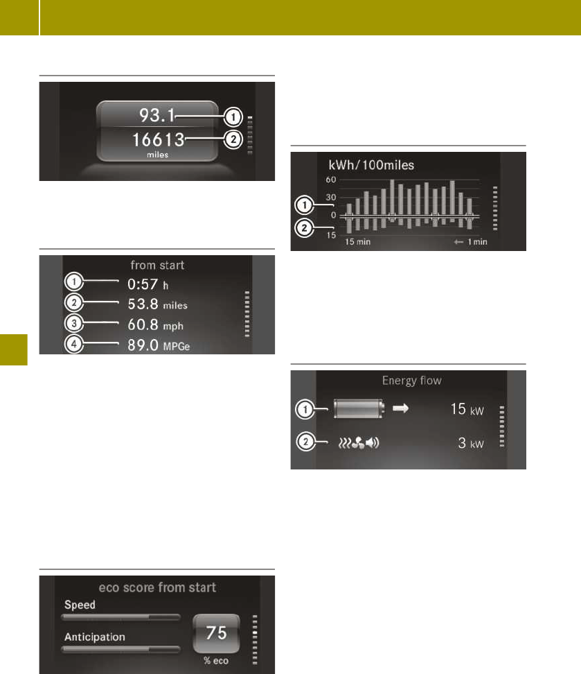
Distance display
:
Trip meter
;
Total distance recorder
Trip computer display
:
Elapsed time
;
Distance
=
Average speed
?
Average energy consumption
The data in the from start menu refers to
the start of the journey, whilst the data in
the from reset menu refers to the last time
the submenu was reset.
If the ignition remains switched off for lon-
ger than four hours, the from start values
in the instrument cluster are reset. The eco
score display is also reset automatically.
eco score display
The eco score display provides feedback on
how economical the driver's driving behav-
iour is (Y page 72).
If the ignition remains switched off for lon-
ger than four hours, the eco score display
will be automatically reset.
When the eco score display is reset, the
from start trip computer in the smart
Media-System and the eco score display are
also reset in the smart Media-System.
Energy consumption bar chart display
:
Energy consumption
;
Recuperation
The display shows the average energy con-
sumption and recuperation over the previ-
ous 15 minutes.
Energy flow display
:
Total output
;
Output for electrical consumers
The total output shows the driver the sum
of the energy currently flowing from the
battery. The colour of the battery shows
whether energy is being consumed or recu-
perated:
R
Battery symbol is orange: energy is being
consumed.
R
Battery symbol is green: energy is being
recuperated.
R
Battery symbol is grey: energy consump-
tion and recuperation are equal or both
at 0 kW.
The output for electrical consumers shows
the driver what output is needed to operate
electrical consumers, e.g. climate control
systems or the radio. If the value is kept as
low as possible, a greater range is achieved.
108
Calling up displays
>> Operating the on-board computer.

Pre-entry climate control and charging
display
:
Time of the full charge
;
Charge status of the battery
=
Departure time
?
Smart-Charging
A
Charge current and charge output
An arrow underneath the battery indicates
the charge status of the battery at the
departure time. The charge status and the
time of complete charge are only predicted
approximately. The time of complete charge
cannot be displayed when Smart-Charging
has been activated.
Information on the "Pre-entry climate con-
trol at departure time" function (Y page 98).
Messages and service display
:
Message memory
;
Next service due date
The display shows the number of display
messages in the message memory and the
next service due date.
¯ indicates a minor service. ° indi-
cates a major service.
To show the display messages, the ignition
must be switched on.
X
Press a to scroll through the display
messages.
Current information on the type of service
can be obtained at a smart centre or a
qualified specialist workshop.
Digital speedometer display
The display shows the digital speedometer.
The digital speedometer in the header is
hidden.
United Kingdom only: the digital speedom-
eter in the header continues to be dis-
played.
Setting values
Setting values (monochrome display)
Setting the time
X
Press ´ repeatedly until ° is
shown next to the time.
X
Press a until the hour display flashes.
X
Set the values.
Activating/deactivating Active Brake
Assist
X
Press ´ several times until Ä and
° are displayed.
X
Press a until ON or OFF appears below
Ä.
The ^ indicator lamp lights up when
Active Brake Assist is deactivated.
Resetting values
The trip meter display and eco score dis-
play can be reset.
X
Scroll to the desired display.
X
Press a for three seconds.
Setting values (colour display)
Setting values
Setting values
109
>> Operating the on-board computer.
Z

X
Press 9 or : to scroll to Settings.
X
Press 9 or : to scroll to the
desired menu.
X
Press 9 or : to set the desired
value.
X
Press a to confirm.
Resetting values
To reset the values in the respective dis-
plays, select the following:
X
Press a.
X
Select yes and press a to confirm.
Setting the time
X
Select Settings > Time > Set the time.
X
Set the values.
Vehicles with smart Media-System: if
available, the time and time format are
set in the smart Media-System.
Setting the time format
X
Select Settings > Time > Time format
(12/24 h).
X
Set the value.
Adjusting the instrument lighting
X
Select Settings > Display > Display/
switch brightness.
X
Set the value.
Displaying the digital speedometer in
the header
X
Select Settings > Display > Digital
speedometer.
X
Select the Disp. addit. dig. speedo.
function.
The digital speedometer is displayed in
the header.
UK only: the digital speedometer in the
header cannot be hidden.
Setting the unit for speed in the digital
speedometer
X
Select Settings > Display > Digital
speedometer > Unit.
X
Set the value.
The following values are set:
R
Digital speedometer display
R
Digital speedometer in the header
UK only: only the display unit of the digital
speedometer is set.
Setting the unit of measurement for
distance
X
Select Settings > Display > Units of
distance.
X
Set the value.
Setting the temperature unit of meas-
urement
X
Select Settings > Display > Units of
temperature.
X
Set the value.
Switching radar-based recuperation off
and on
To switch on radar-based recuperation, the
conditions for activation must be fulfilled
and the ignition must be switched on.
X
Select Settings > Radar assist. recu‐
peration > on or off.
Information on radar-based recuperation
(Y page 69).
Activating/deactivating Active Brake
Assist
The ignition must be switched on in order
to set Active Brake Assist.
X
Select Settings > Active Brake Assist >
on or off.
Information on Active Brake Assist
(Y page 58).
110
Setting values
>> Operating the on-board computer.

Starting the tyre pressure monitor
X
Select Settings > Tyre pressure moni‐
tor.
Information on the tyre pressure monitor
(Y page 163).
Switching ambient lighting on/off
X
Select Settings > Ambient lighting > On.
Setting the brightness of the ambient
lighting
X
Select Settings > Ambient lighting >
Brightness.
X
Set the value.
Setting the language
X
Select Settings > Language (Language).
X
Set the value.
Setting values
111
>> Operating the on-board computer.
Z

Operating and setting the smart
Audio-System
smart Audio-System overview
G
WARNING
If you operate information and communi-
cation equipment integrated in the vehi-
cle when driving, you could be distracted
from the traffic situation. This could also
cause you to lose control of the vehicle.
There is a risk of an accident.
Only operate this equipment when the
traffic situation permits. If you cannot be
sure of this, stop the vehicle paying
attention to road and traffic conditions
and operate the equipment with the vehi-
cle stationary.
You must observe the legal requirements
for the country in which you are currently
driving when operating the smart Audio-
System.
:
Number keys 1 - 6
;
C Previous station or track
=
USB1 connection
?
D Next station or track
A
% Goes back one menu level higher
B
Control for menu selection and station
list, 9 button
C
USB2 port
D
à Telephone menu to accept or reject
calls
E
ª System settings
F
8 Mute
G
Õ Plays back media from external
data storage media
H
$ Switches on the radio and selects
the waveband
I
External audio equipment (AUX connec-
tion)
J
Volume control, Ü button
K
F Sets the radio text
Operating and setting the smart
Audio-System
X
To switch on or off: press Ü.
X
To scroll through menus: turn control B.
X
To select menu options: turn control B
and press the 9 button.
X
To navigate to the next-highest folder:
press the % button.
X
To set values: turn control B and press
the 9 button.
X
To increase or decrease the volume: turn
control J.
Using external devices
Useful information
You can connect the following external
devices:
R
USB devices, iPods
®
and MP3 players (USB
port)
R
External audio equipment (AUX connec-
tion)
R
Bluetooth
®
devices, such as mobile
phones
External devices can be charged at USB
ports = and C when the ignition is
switched on. It is better to use USB port =
for charging as it supplies a higher charge
current. To charge an external device
remove the cover on USB port =.
112
Operating and setting the smart Audio-System
>> Using the smart Audio-System.

Removing and fastening the cover of
the USB1 port
X
To remove: turn the cover anti-clockwise
using handle :.
X
Move the cover into position ;.
X
Remove the cover.
X
To secure: place the cover in position ;.
X
Turn the cover clockwise using han-
dle :.
Adjusting the system settings
Setting the system language
X
Press the ª button.
X
Select Language.
The list of languages appears.
X
Select the language.
Switching the time on/off
X
Press the ª button.
X
Select Clock.
X
Select ON or OFF.
Setting the time
X
Press the ª button.
X
Select Clock.
X
Select Set Time.
X
Set the time.
Setting the time format
X
Press the ª button.
X
Select Clock.
X
Select Format.
Select one of the following time formats:
R
Am/Pm
R
24hr
Adjusting the audio settings
Adjusting the sound
X
Press the ª button.
X
Select Audio.
X
Select Sound.
Select the desired sound setting:
R
Bass: adjusts the bass.
R
Treble: adjusts the treble.
R
Bal.: adjusts the surround sound (bal-
ance) to left or right.
Switching the bass boost on/off (vehi-
cles without JBL sound system)
X
Press the ª button.
X
Select Audio.
X
Select Bass Boost.
X
Select ON or OFF.
Resetting audio settings
X
Press the ª button.
X
Select Audio.
X
Select Audio Default.
X
Select Yes.
Adjusting the volume to the vehicle
speed (vehicles without JBL sound sys-
tem)
X
Press the ª button.
X
Select Audio.
X
Select Speed Vol..
X
Select the desired level.
The higher the level, the higher the vol-
ume will be at increasing road speeds.
Operating and setting the smart Audio-System
113
>> Using the smart Audio-System.
Z

Listening to the radio
Switching on the radio
X
Press the Ü button.
X
Press the $ button.
The smart Audio-System receives data
transmitted via the Radio Data System
(RDS).
Setting the waveband
X
Press the $ button repeatedly until
the desired waveband appears.
If available, you can switch between the
following wavebands:
R
FM1
R
FM2
R
DR1 (digital radio)
R
DR2 (digital radio)
R
AM
Selecting stations manually
FM and AM waveband
X
Press the D or C button to set the
desired frequency.
Digital radio frequency range
X
To select the desired station, press the
D or C button.
Setting a station from the station list
X
Press a in radio mode.
The station list appears.
X
Select a station.
X
Press a to confirm.
Updating the station list
X
Press the $ button until you hear a
tone.
Storing a station
X
Select the waveband.
X
Set the station.
X
Press a number key 1 to 6 until you
hear a tone.
The station set for this waveband will be
stored on the button you have pressed.
Selecting a stored station
X
Select a waveband.
X
Press a number key for the stored station.
Switching traffic announcements
on/off
X
Press the ª button.
X
Select Radio.
X
Select TA.
X
Select ON or OFF.
Interrupting a traffic announcement
X
During a traffic announcement, briefly
press %.
Displaying radio text in FM radio
X
Press the F button.
If radio text is available, it will be dis-
played.
Digital radio (if available)
Information on DAB
i
Any electronic devices taken into the
vehicle may seriously impair radio and
DAB radio reception.
Digital radio or DAB (Digital Audio Broad-
casting) is a digital transmission standard
optimally designed for the mobile reception
of radio transmissions. Several programmes
are combined into so-called ensembles and
transmitted on a single frequency. Some
stations only transmit programmes at cer-
114
Listening to the radio
>> Using the smart Audio-System.

tain times. If you have selected a pro-
gramme that has subsequently been
removed from the ensemble, it will no lon-
ger be received. You will continue to
receive the other programmes in the
ensemble. Select either a different pro-
gramme or a different ensemble.
i
DAB cannot be received everywhere in
Europe.
Displaying radio text
This function provides additional data
transmitted in the DAB waveband (DR1 and
DR2). Besides displaying the artist and
track names, information on the current
programme may also be available.
X
Press the F button.
X
Select Radio text.
The î dot shows that radio text is acti-
vated.
Setting alerts
If this function is activated, certain pro-
gramme categories allow another broadcast
to interrupt the current audio playback.
Numerous categories can be selected, such
as news, business news, sports news etc.
A prerequisite for the reception is that
broadcasters process the relevant informa-
tion. This function is only available in cer-
tain countries.
X
Call up the setup menu (Y page 113).
X
Select Radio > DR Interrupt… > Desired
category.
The î dot shows the active settings.
i
Several categories can be selected.
Repeat the procedure if necessary.
Displaying the EPG
EPG (Electronic Program Guide) is available
in the DAB waveband (DR1 and DR2).
If the station supports EPG, you can use the
EPG (Electronic Programme Guide) to dis-
play the current and the following two
radio programmes. At the very least, the
programme overview contains the name,
time and length of each programme.
X
Press the F button.
X
Select EPG.
X
Select the desired station.
Switching on Intellitext™
If the station supports Intellitext™, you can
have additional information displayed,
such as news, headlines, business news,
sports news etc. A prerequisite for the
reception is that broadcasters process the
relevant information. Intellitext™ is only
available in certain countries.
X
Press the F button.
X
Select Intellitext.
Using a mobile phone
Connecting a mobile phone
Useful information
The Bluetooth
®
-capable mobile phone must
be compatible with the smart Audio-Sys-
tem. Overview of compatible mobile phones:
http://www.smart.com/connect.
To make a call, Bluetooth
®
must be activa-
ted on the mobile phone and the smart
Audio-System.
Once outside the Bluetooth
®
reception
range, the connection is terminated auto-
matically.
To clearly identify a mobile phone, change
the device name (see the manufacturer's
operating instructions).
Activating Bluetooth
®
on a mobile
phone
X
Activate Bluetooth
®
on the mobile phone
(see the manufacturer's operating
instructions).
X
Search for devices.
Using a mobile phone
115
>> Using the smart Audio-System.
Z

Switching on the Bluetooth
®
function of
the smart Audio-System
X
Press the à button.
X
Turn control B to Bluetooth and confirm
with 9.
X
Turn control B to ON and confirm with
9.
The î dot shows the active setting.
Authorising a mobile phone on the
smart Audio-System
X
Press the à button.
X
Select Scan devices.
The system searches for available mobile
phones and displays them in a list.
X
Select a mobile phone confirm with 9.
X
Authorise the mobile phone with the
smart Audio-System.
The following options are available:
R
if a code appears in the smart Audio-Sys-
tem display and on the mobile phone,
confirm it on the mobile phone
R
if the code 0000 appears in the smart
Audio-System display, enter it and con-
firm it on the mobile phone
A maximum of five mobile phones can be
authorised. However, only one authorised
mobile phone can be connected with Blue-
tooth
®
at a time.
Loading and updating the phone book
X
Press the à button.
X
Select Settings > PB download.
X
If necessary, accept the access confirma-
tion on the mobile phone.
If the mobile phone supports the Bluetooth
®
PBAP (Phone Book Access Profile) profile,
the phone book and call lists will be trans-
ferred after you connect.
Removing a mobile phone from the list
(de-authorising)
X
Press the à button.
X
Select Del. device.
Authorised mobile phones are displayed.
X
Select the mobile phone to be deleted.
X
Select Yes.
After de-authorisation, the Bluetooth
®
con-
nection to the mobile phone is no longer
established automatically.
Connecting another authorised mobile
phone
X
Activating Bluetooth
®
on a mobile phone
X
Press the à button.
X
Select Sel. device.
All authorised mobile phones are dis-
played. The currently connected mobile
phone is indicated by a dot.
X
Select the desired mobile phone from the
list.
Setting the sound
Adjusting the call volume
X
Press the à button.
X
Select Settings > Volume > Call.
X
Select the value.
Switching the smart Audio-System
ringtone on and off
X
Press the à button.
X
Select Settings > Ringtone.
X
To switch on: select Car.
X
To switch off: select Phone.
Adjusting the ringtone volume
X
Press the à button.
X
Select Settings > Volume > Ring.
X
Select the value.
Telephone operation
Calling a contact from the phone book
To call a contact in the phone book, the
mobile phone telephone book first has to be
imported into the smart Audio-System.
116
Using a mobile phone
>> Using the smart Audio-System.

X
Press the à button.
X
Select Phonebook.
X
Select the contact.
The details for the contact are displayed.
X
Select the desired phone number.
X
Press the 9 button.
Dialling a phone number
X
Press the à button.
X
Select Dial a number.
An input screen appears.
X
Enter the number.
X
Press the 9 button.
X
Select ;.
Using call lists to call contacts
To call a contact in a call list, the mobile
phone telephone book first has to be impor-
ted into the smart Audio-System.
X
Press the à button.
X
Select Call List.
X
Select Dialled, Received or Missed.
X
Select an entry from the list.
Calling the last number dialled
X
Press and hold the à button until the
call is established.
Accepting a call
X
Press the à button.
or
X
Briefly press the button on the
steering wheel.
Rejecting a call
X
Press and hold the à button.
or
X
Press and hold the button on the
steering wheel until the call is rejected.
Holding and continuing a call
X
To hold: select Â.
X
To continue the call: press the 9 button.
Transferring a call to the mobile phone
X
Select z.
X
To transfer the call back to the smart
Audio-System: press the 9 button.
Entering numbers or characters during
a call
X
Select #123.
X
Enter numbers or characters.
Ending a call
X
Press the 9 button.
or
X
Press the button on the steering
wheel.
Using voice control for the mobile
phone
Useful information
The voice control of the connected mobile
phone can be used (see manufacturer's
operating instructions). Not all voice con-
trol services are supported by the smart
Audio-System.
Voice control must be activated in the set-
tings menu of the mobile phone.
Starting voice control of the mobile
phone
X
Connect the mobile phone with the smart
Audio-System via Bluetooth
®
.
X
Press the button on the steering
wheel.
A message appears in the display of the
smart Audio-System and a tone sounds.
Voice control for the mobile phone is
active.
X
Say a command.
Using a mobile phone
117
>> Using the smart Audio-System.
Z

Ending voice control of the mobile
phone
X
Press the button on the steering
wheel.
or
X
Press the 9 button.
Voice control of the mobile phone is
ended.
Operating external data storage media
Useful information
You can switch between the following
media sources, depending on the type of
external data storage media connected:
R
USB 1 or iPod
®
1
R
USB 2 or iPod
®
2
R
AUX (external audio equipment)
R
BT Audio (with Bluetooth
®
connected
device, such as a mobile phone)
Selecting external data storage media
X
Press the Õ button repeatedly until
the desired media source appears in the
display.
Operating a USB device or iPod
®
Connecting a device
X
Connect the device to the USB port.
The device is activated automatically and
the first track is played.
Selecting a track
X
In USB mode, press the 9 button.
Available tracks or folders are displayed.
X
Turn control B.
X
Press 9 to confirm.
Rapid search
X
Press the 9 button.
An entry field appears.
X
To enter characters, turn control B and
press the 9 button.
Skipping to the next or previous track
X
Press the D or C button briefly to
skip to the next track or press longer for
rapid scrolling.
Switching random track sequence on/off
X
Press the C button.
Switching the repeat function on/off
X
Press the number key.
Selecting a track from a category with
an iPod
®
connected
X
Press the 9 button.
X
Select a category from the list.
Different categories, such as playlists,
artists or albums, can be selected,
depending on the connected device.
Displaying metadata
X
Press the F button repeatedly until
the desired metadata is displayed.
Operating external audio equipment
(AUX)
Connecting a device
X
Connect the device to the AUX jack.
Use the Õ button to access the media
on a connected AUX device.
Adjusting the volume of external audio
equipment
X
Press the ª button.
X
Select Audio.
X
Select AUX In.
118
Operating external data storage media
>> Using the smart Audio-System.

Select one of the following options for the
volume:
R
Low
R
Medium
R
High
Bluetooth
®
device operation
Connecting a device
X
Connect a Bluetooth
®
audio device the
same way you connect a mobile phone
with Bluetooth
®
.
Skipping to the next or previous track
X
Press the D or C button briefly to
skip to the next track or press longer for
rapid scrolling.
Displaying metadata
X
Press the F button repeatedly until
the desired metadata is displayed.
Operating external data storage media
119
>> Using the smart Audio-System.
Z

Operating and setting up the smart
Media-System
Operating the smart Media-System
Please note
Some functions are restricted while driving.
Controls
:
Switches voice control system on/
off, accepts and ends a phone call
;
W Increases the volume
=
X Reduces the volume
?
smart Media-System display
Voice control system
The following functions are possible using
the voice control system of the smart
Media-System:
R
enter a destination for navigation
R
make a call
R
start an application
Controls on the smart Media-System
:
Previous station or track and fast
rewind
;
Mute
=
Next station or track and fast forward
?
Switches to the home screen
A
Ü On/off button and volume control
B
Touchscreen
Ports on the centre console
:
Port for external audio equipment (AUX)
;
USB port
=
SD card slot
Some devices, for example mobile phones or
USB drives, connect with the smart Media-
System via USB port ;. External devices
with 5 V (1 A) can be charged on USB port ;
when the ignition is switched on.
120
Operating and setting up the smart Media-System
>> Using the smart Media-System.

Overview of home screen
X
To call up a function, tap on an area on
the home page or on a symbol.
The following functions can be selected:
R
:: to switch to radio or media applica-
tion
R
;: to call up message memory
R
=: to switch to telephone application
R
?: to call up the weather forecast for the
current location
R
A: to display time and temperature in
full screen or to call up time settings
R
B: to switch to full screen navigation
view
R
C: next navigation manoeuvre is dis-
played
R
D: to change language, change home
page, remove an SD card or switch off the
display
R
E: distance to the destination and esti-
mated time of arrival are displayed
R
F: to view, call up or change favourites
R
G: to call up the main menu
R
H: to switch to telephone application
i
The home screen can be set to display
the energy flow.
If the home page is set so as to display the
eco score, you can switch to the eco score
application by tapping on the area.
When Android Auto™ or MirrorLink
®
is
active, another symbol is displayed on the
home page. You can switch to the relevant
smartphone screen application by tapping
on the symbol.
Switching the smart Media-System
on/off
Switching on automatically
X
Start the engine.
Switching off automatically
X
Switch off the ignition and open the door.
Switching on/off manually
X
Press the Ü button.
Restarting
X
Press the Ü button five times.
The smart Media-System shuts down and
restarts.
i
The restart can take several minutes.
During the restart, the audio volume can-
not be adjusted.
Scrolling through a menu or list on the
touchscreen
X
Touch the touchscreen with your finger.
X
Swipe up, down, left or right.
The selection on the display will then
move in the respective direction.
Selecting items on the touchscreen
X
Tap on a menu, an option or an applica-
tion with one finger.
The menu, the option or the application is
launched.
Controlling media playback on the
touchscreen
X
Swipe to the left.
The next media item is played or dis-
played, e.g. the next track or station.
X
Swipe to the right.
Playback is restarted or the previous
media item is played or displayed, e.g.
the previous track.
Media playback can be controlled in the
following playback modes:
R
Radio mode
R
Music and audio playback
Operating and setting up the smart Media-System
121
>> Using the smart Media-System.

R
Image playback
R
Video playback
Calling up menus
X
Select Menu on the home screen.
X
Select one of the following submenus.
Submenus:
R
Multimedia
Radio and media playback
R
Navigation
Navigation system
R
Telephone
Mobile phone functions
R
Vehicle
Reversing camera, eco score, energy flow
and consumption details
R
Services
TomTom Services
R
System
General system settings
Confirming settings
X
Select Done.
Settings are accepted.
Switching off the display
X
Select home page > W > Switch off
screen.
Adjusting the system settings
Adjusting the display
Setting the daytime brightness
X
Select System > Display.
X
Move the Daytime brightness control to
the left or right.
Setting the night-time brightness
X
Select System > Display.
X
Move the Nighttime brightness control
to the left or right.
Activating automatic switching between
day and night mode
X
Select System > Display > Automatic
day/night mode.
Displaying day mode constantly
X
Select System > Display.
X
Remove the tick for Automatic day/
night mode and Force night mode.
Displaying night mode constantly
X
Select System > Display > Force night
mode.
Setting the system language
X
Select System > Language.
A list of available languages is displayed.
X
Select the desired language.
i
The language of the spoken navigation
announcement can be selected independ-
ently of the system language.
Changing the on-screen keyboard
X
Select System > Keyboards.
X
Select the keyboard layout.
The following keyboard layouts can be
selected:
R
Latin
R
Greek
R
Cyrillic
For the Latin keyboard layout, it is possi-
ble to choose between the ABCD, QWERTY,
AZERTY and QWERTZ layouts.
Selecting the home screen display
Different displays are available for the
home page which display up-to-date infor-
mation about the applications in the smart
Media-System.
X
Select System > Home page.
A selection of home screen displays
appears.
X
Select the desired display.
122
Operating and setting up the smart Media-System
>> Using the smart Media-System.

Resetting to factory settings
X
Select System > Restore factory set‐
tings.
X
Confirm with Yes.
All settings changed in the system return
to the default values. All destinations,
routes and favourites will be deleted.
Setting the time manually
X
Select System > Clock > Set time.
X
Change the minutes and hours of the time
shown.
Activating automatic time adjustment
X
Select System > Clock > Set time > Auto‐
matic time adjustment.
Setting the time format
X
Select System > Clock > Time format.
X
Select the time format.
The following time formats can be selec-
ted:
R
18:00
R
6:00 PM
R
6:00
Displaying status and information
X
Select System > Status & Information.
X
Select the information.
The following information can be selec-
ted:
R
Version information
Software and hardware of the Media-
System
R
GPS status
Current GPS signal strength
R
Network status
Signal strength of the data connection
R
Licences
For free and open-source software used
R
Copyright
For text in the TomTom software used.
Adjusting the audio settings
Setting the volume
X
Select System > Sound > Sound levels.
X
Select the volume setting.
The following volume settings can be
selected:
R
Main volume
For the whole system
R
Hands-free
For the hands-free system
R
Ringtone
Ring tone volume
R
Navigation
Volume for the whole navigation sys-
tem
R
Computer voice
Volume of the computer-generated
voice
R
App events
Volume of events triggered by apps
X
Set the desired volume.
Adjusting the volume to the vehicle
speed (vehicles without JBL sound sys-
tem)
The speed-dependent volume adjustment
function adapts the volume to the current
vehicle speed.
X
Select System > Sound > Speed sensitiv‐
ity volume.
X
Move the Speed sensitivity volume
control to the left or right.
The higher the value, the more the vol-
ume increases with the speed of the vehi-
cle.
Volume adjustment is not set using the
control but automatically.
Adjusting surround sound (balance)
X
Select Multimedia > Settings > Sound >
Balance > Manual.
X
Move the control to the desired position.
X
Confirm with Done.
Operating and setting up the smart Media-System
123
>> Using the smart Media-System.

Adjusting the bass and treble
X
Select Multimedia > Settings > Sound >
Bass/Treble > Manual.
X
Use the control to adjust the bass and
treble separately.
Setting a neutral sound for the bass and
treble
X
Select Multimedia > Settings > Sound >
Bass/Treble > Neutral.
Audio is played without increasing the
bass or treble.
Activating/deactivating arkamys
®
bass
boost (vehicles without JBL sound sys-
tem)
The arkamys
®
bass boost setting emphasi-
ses the bass during playback.
X
Select Multimedia > Settings > Bass
boost Arkamys.
Manual activation of arkamys
®
bass boost
on models with a JBL sound system is not
possible. Activation functions automati-
cally.
Setting the volume for warning tones
X
Select System > Sound > Alerts.
X
Move the control to the left or right.
Enabling warning tones when the dis-
play is switched off
X
Select System > Sound > Alerts > Keep
audio alerts when screen turned off.
Creating and deleting favourites
Creating favourites
:
Preset
;
Navigation
=
Radio
?
Telephone
A
Services
B
Context menu
Frequently used settings such as phone
contacts and radio stations can be stored as
favourites. Six favourites can be stored for
each of the following categories:
R
Navigation
R
Radio
R
Telephone
R
Services
X
Select Favourites on the home screen.
X
Select a category.
X
Select the next empty memory position.
A list of possible favourites appears.
X
Select favourites.
Deleting favourites
X
Select Favourites on the home screen.
X
Select W > Remove a Favourite.
X
Delete a favourite.
The following options can be selected:
R
Select the favourite you wish to delete
and confirm with Delete.
R
To delete all favourites, select Remove
all Favourites.
124
Operating and setting up the smart Media-System
>> Using the smart Media-System.

Listening to the radio
Switching on the radio
X
Select Multimedia > Radio.
Display modes
Useful information
In radio mode there are three different dis-
play modes, in which various settings can
be made:
R
"List" display mode (FM and digital radio)
R
"Frequency" display mode (AM and FM
radio)
R
"Presets" display mode
"List" display mode (FM and digital
radio)
:
Selects the waveband (AM/FM/DAB
radio) and preset group (FM/DAB)
;
Selects the previous station
=
Selects the next station
?
Context menu
A
"Frequency" display mode
B
"List" display mode
C
"Presets" display mode
D
Station currently playing
"Frequency" display mode (AM and FM
radio)
:
Selects the waveband (AM/FM radio) and
preset group (FM)
;
Increases or decreases the frequency in
small increments
=
Station search, forwards or backwards
?
Context menu
A
Adjusts the frequency manually
B
Station currently playing
"Presets" display mode
:
Selects the waveband (AM/FM/DAB
radio) and preset group (FM/DAB)
;
Stored station
=
Context menu
?
Station currently playing
Selecting a station
"List" display mode
X
Swipe up or down in the station list.
X
Tap on the desired station.
Listening to the radio
125
>> Using the smart Media-System.

"Frequency" display mode (AM and FM
radio)
X
Slide control on the waveband left or
right.
Starting a station search
X
Select C or D in the "Frequency"
display mode.
Storing a station
X
Set the station.
X
Select W > Save as preset.
Up to six stations can be stored for each
waveband.
Displaying radio text
Radio text contains information such as
current track or latest news.
X
Select W > Show radio text.
Displaying digital radio services
X
Select W > DR services.
X
Select one of the following digital radio
services:
Digital radio services:
R
EPG
Programme schedule for the station
currently playing
R
Intellitext
Programme information and pro-
gramme schedule for the station cur-
rently playing
R
Slide show
Displays images to accompany the cur-
rent broadcast
Other radio settings
Searching for alternative frequencies
with the best possible reception quality
X
Select Multimedia > Settings > Radio >
AF (Alternative frequency).
Receiving traffic reports (i-Traffic)
X
Select Multimedia > Settings > Radio > i-
Traffic (Traffic program).
Displaying the programme type (e.g.
classical)
X
Select Multimedia > Settings > Radio >
PTY (Program type).
Switching to the corresponding FM sta-
tion when digital radio reception is poor
X
Select Multimedia > Settings > Radio >
Simulcast.
Displaying information on certain cate-
gories (i-Announcement, digital radio
only)
X
Select Multimedia > Settings > Radio > i-
Announcement.
X
Select an i-Announcements category.
Updating the station list
X
Select Multimedia > Settings > Radio >
Update radio list.
Displaying energy consumption
Calling up the energy flow display
X
Select Menu > Vehicle > Energy consump‐
tion > Energy flow.
The Energy flow display shows the flow of
energy in the vehicle.
126
Displaying energy consumption
>> Using the smart Media-System.

The colour of the energy flow indicates the
following:
R
Green colouring: energy is being recu-
perated
R
Orange colouring: the drive is consuming
energy
R
Yellow colouring and an illustration of
the consumers: electrical consumers are
consuming energy
R
Grey colouring: no energy is being recu-
perated or consumed
Calling up the detailed consumption
display
X
Select Menu > Vehicle > Energy consump‐
tion > Consumption details.
The Consumption details display shows
the energy consumption of the drive and
electrical consumers as well as the energy
recuperated over the previous 15 minutes.
The display also shows the total consump-
tion of the drive and electrical consumers
as well as the total amount of energy recu-
perated during the current journey.
The Consumption details display is reset
each time the engine is switched on.
Using a mobile phone
Connecting a mobile phone
Please note
G
WARNING
The electromagnetic radiation from two-
way radios can interfere with the vehicle
electronics if they are manipulated or
retrofitted incorrectly. This could jeop-
ardise the operating safety of the vehicle.
There is a risk of an accident.
You should have all work on electrical
and electronic components carried out at
a qualified specialist workshop.
G
WARNING
If you operate two-way radios incorrectly
in the vehicle, their electromagnetic
radiation can interfere with the vehicle
electronics, for example if:
R
the two-way radio is not connected to
an exterior aerial
R
the exterior aerial is not correctly
mounted or is not low-reflection
This could jeopardise the operating
safety of the vehicle. There is a risk of an
accident.
Have the low-reflection exterior aerial
fitted at a qualified specialist workshop.
When operating two-way radios in the
vehicle, always connect them to the low-
reflection exterior aerial.
Bluetooth
®
must be enabled both on the
mobile phone and on the smart Media-Sys-
tem.
Enabling and disabling Bluetooth
®
The mobile phone must be compatible with
the smart Media-System.
Overview of compatible mobile phones:
http://www.smart.com/connect.
X
Select Settings > Turn Bluetooth on.
The setting is marked. Bluetooth
®
is ena-
bled or disabled on the smart Media-Sys-
tem.
Authorising a mobile phone
Authorising a mobile phone for the first
time
Bluetooth
®
must be enabled on the smart
Media-System.
X
Select Phone menu.
X
Confirm the display message with Yes.
X
Enter the security code on the mobile
phone or accept access confirmation (see
manufacturer's operating instructions).
The Enabling Bluetooth message
appears.
Using a mobile phone
127
>> Using the smart Media-System.
Z

Authorising another mobile phone
Bluetooth
®
must be enabled on the smart
Media-System.
X
Select Settings > Manage devices.
The list of visible mobile phones appears.
X
Select the mobile phone from the list.
X
Enter the security code on the mobile
phone or accept access confirmation (see
manufacturer's operating instructions).
The Bluetooth
®
connection is established.
The Bluetooth
®
connection will be estab-
lished automatically in future.
Downloading telephone data automati-
cally
X
Select Settings > Automatically down‐
load phone data.
X
If necessary, accept the access confirma-
tion on the mobile phone.
During connection, up to 1,000 contacts
are automatically transferred to the
smart Media-System.
Connecting another authorised mobile
phone
X
Select Settings > Manage devices.
X
Select the mobile phone.
The current Bluetooth
®
connection is ter-
minated. The desired mobile phone is
connected to the smart Media-System
instead.
Removing a mobile phone from the list
X
Select Settings > Manage devices.
X
Select W > Delete device(s).
X
Select the mobile phone.
X
Select Delete.
Terminating a Bluetooth
®
connection
X
Select Settings > Manage devices.
X
Select W > Disconnect all devices.
X
Select the mobile phone.
If the mobile phone leaves the Bluetooth
®
receiver range, the connection is automati-
cally terminated.
Telephone operation
Useful information
The following conditions must be fulfilled
in order to make a 999 or 112 emergency
call:
R
a valid and operational SIM card is inser-
ted in the mobile phone
R
a mobile phone network is available
Calling a contact from the phone book
X
Select Phonebook.
X
Select the contact.
X
Select the contact's telephone number.
If the phone book contains multiple con-
tacts, they can be called up using Find.
Dialling a phone number
X
Select Dial a number.
X
Enter a number on the keypad.
X
Select Call.
Calling a contact from the call log
X
Select Call logs.
X
Select an entry from the list.
The call log can be sorted according to calls
made, calls received and missed calls using
the corresponding receiver icon.
Accepting and rejecting an incoming
call
If a call is incoming, the following informa-
tion will appear on the display:
R
name of caller, if already in the phone
book
R
number of caller, if name of caller is not
already in the phone book
R
Private number, if the caller has the
"Hide caller ID" function switched on
X
To accept the call, select Pick up.
X
To reject the call, select Refuse.
The call will be forwarded to voicemail.
128
Using a mobile phone
>> Using the smart Media-System.

Holding and continuing a call
X
Select W > Put on hold.
X
To continue the call, select Resume.
Transferring a call to the mobile phone
X
Select W > Handset.
Ending a call
X
Select End call.
Using the smartphone screen applica-
tion
Selecting settings for the smartphone
screen
Selecting the preferred smartphone
screen application
If mobile phones support Android Auto™ as
well as MirrorLink
®
, the preferred applica-
tion can be selected when a mobile phone is
connected.
X
Select System > Smartphone Screen >
Smartphone Screen application pref‐
erence.
X
Select Android Auto™ or MirrorLink
®
.
Selecting settings to start Android Auto™
and MirrorLink
®
X
Select System > Smartphone Screen >
Android Auto™ Settings.
or
X
Select System > Smartphone Screen >
MirrorLink™ Settings.
X
Start smartphone screen application
Select one of the following settings:
R
Ask me at each launch
If the smartphone has been connected
with the smart Media-System, you will
be asked whether the preferred smart-
phone screen application should be
started.
R
Yes
If the smartphone has been connected
with the smart Media-System, the pre-
ferred smartphone screen application
will be started automatically.
R
No
If the smartphone has been connected
with the smart Media-System, a smart-
phone screen application will not be
started.
Using MirrorLink
®
Useful information
MirrorLink
®
is a standard for the connec-
tion between the smart Media-System and a
mobile phone. With MirrorLink
®
, the con-
tent of the display on your mobile phone
can be displayed in the smart Media-Sys-
tem.
MirrorLink
®
is available for mobile phones
with the Android™ operating system.
Further information: http://
www.smart.com/connect.
To use MirrorLink
®
, observe the following
requirements:
R
the mobile phone must support Mirror-
Link
®
version 1.1 and above
R
the mobile phone is switched on
R
a MirrorLink
®
certified app must be
installed on the mobile phone
R
the GPS connection must be activated on
the mobile phone
R
the time is set on the smart Media-Sys-
tem
Setting up a connection
X
Activate MirrorLink
®
on your mobile
phone (see the manufacturer's operating
instructions).
X
Connect a mobile phone with a connect-
ing cable to the USB socket in the centre
console.
X
Select Yes.
Apps which have been certified for Mir-
rorLink
®
will be shown in the smart
Media-System display.
Using a mobile phone
129
>> Using the smart Media-System.
Z

Calling up MirrorLink
®
apps
X
Tap 0 on the home page of the smart
Media-System.
MirrorLink
®
starts in the smart Media-
System display.
X
Select the desired app.
The display switches to full screen mode.
X
To leave full screen display: press and
hold the ò button on the smart Media-
System until the lower bar is shown.
X
To leave the display: select 2.
MirrorLink
®
audio playback
If your mobile phone supports this func-
tion, you can control audio playback via the
buttons on the smart Media-System.
X
To select the previous track: press the
9 button.
X
To rewind: press and hold the 9 but-
ton.
X
To select the next track: press the :
button.
X
To fast forward: press and hold the :
button.
X
To mute: press the 8 button.
Terminating a MirrorLink
®
connection
X
Select W > Disconnect.
Using Android Auto™
Useful information
Android Auto™ is an application for the
connection between the smart Media-Sys-
tem and a mobile phone. Certain mobile
phone functions and apps can be controlled
via the smart Media-System with Android
Auto™.
Functions such as telephony, navigation
and the audio playback of Android Auto™
are displayed on the home page of the
smart Media-System.
Android Auto™ is available for mobile
phones with the Android™ operating sys-
tem.
Further information: http://
www.smart.com/connect.
In order to use Android Auto™, the follow-
ing conditions must be met:
R
the mobile phone supports Android
Auto™ starting from Android™ 5.0
R
the mobile phone is switched on
R
the mobile phone has an Internet con-
nection
R
the Android Auto™ app is installed on the
mobile phone
R
data sharing must be approved
Transmitted vehicle data when using
Android Auto™
When using Android Auto™, specific vehicle
data is transmitted to the mobile phone.
This makes it possible to use selected
mobile phone services efficiently. The
mobile phone does not have active access to
vehicle data. The following system infor-
mation is transmitted:
R
smart Media-System software status
R
system ID (anonymous)
This data is transmitted in order to opti-
mise communication between the vehicle
and mobile phone.
A random vehicle code is generated for this
purpose and in order to assign multiple
vehicles to the mobile phone. This code is
not related to the vehicle identification
number (VIN) and is deleted if the smart
Media-System is reset. The following driv-
ing status data is transmitted:
R
gear position engaged
R
instrument cluster day/night mode
This data is transmitted in order to adapt
the content displayed to the driving situa-
tion.
GPS data such as coordinates, speed and
compass direction is transmitted. This data
is transmitted only when navigation is
active in order to improve navigation (e.g.
when driving through a tunnel).
130
Using a mobile phone
>> Using the smart Media-System.

Setting up a connection
X
Activate Android Auto™ on the mobile
phone (see manufacturer's operating
instructions).
X
Connect a mobile phone with a connect-
ing cable to the USB socket in the centre
console.
X
Select Yes.
Android Auto™ starts in the smart Media-
System display.
Calling up Android Auto™
X
Tap / on the home page of the smart
Media-System.
Android Auto™ starts in the smart Media-
System display.
Activating Android Auto™ voice-operated
control
When Android Auto™ is activated, the sys-
tem can be operated with voice control.
X
Press and hold the button on the
multifunction steering wheel for approx-
imately three seconds.
A tone sounds.
Disconnecting Android Auto™
X
Disconnect the USB connection between
the mobile phone and the smart Media-
System.
Using voice control for the mobile
phone
Useful information
The voice control of the connected mobile
phone can be used (see manufacturer's
operating instructions). Not all voice con-
trol services are supported by the smart
Media-System.
The requirement for voice control of the
mobile phone is that Android Auto™ or Mir-
rorLink
®
are not active.
Activating voice control for the mobile
phone
X
Connect the mobile phone with the smart
Media-System via Bluetooth
®
.
X
Press and hold the button on the
steering wheel.
The o symbol appears in the display.
Voice control for the mobile phone is
active.
X
Say a command.
Further settings
Setting the volume
X
Select Settings > Sound levels.
X
Set the volume of the hands-free system
and the ringtone.
Activating voicemail
X
Select Voice mail.
X
Enter the voicemail phone number on the
keypad.
X
Select Done.
Voicemail is activated and the voicemail
number is dialled.
Configuring voicemail
X
Select Settings > Voice mail configu‐
ration.
Updating the phone book
A Bluetooth
®
connection must be present.
X
Select Phone book > W > Update
phone data.
Updating the call log
X
Select Call logs > W > Update phone
data.
Adding a contact to favourites
X
Select Phone > Phonebook.
X
Select the contact from the list.
Using a mobile phone
131
>> Using the smart Media-System.
Z

X
Select W > Add to Favourites.
X
Dial a phone number.
Connecting and operating external
data storage media
Useful information
The following external data storage media
can be connected:
R
USB memory stick (USB 2.0 or 3.0 with
max. 64 GB) or iPod
®
R
SD or SDHC card (max. 64 GB)
R
External audio equipment (AUX connec-
tion)
R
Bluetooth
®
devices such as mobile phones
The following formats are supported:
R
MP3 files
R
WMA files
R
ACC formats
(.AAC, .M4A, .M4B, .M4P, .M4V, .M4R
and .MP4)
R
OGG Vorbis (.OGG, .OGA)
R
PCM 16 bit (.WAV, .PCM)
A data storage medium may contain no
more than eight directory levels.
The smart Media-System only recognises
the first partition of a data storage medium.
The partition must be formatted as FAT or
FAT32.
Connecting external data storage
media
Connecting a USB memory stick
X
Insert a USB memory stick in the port on
the centre console.
Playback starts automatically.
Connecting an SD card
X
Insert an SD card into the SD card slot in
the centre console.
Playback starts automatically.
Connecting a Bluetooth
®
device
X
Authorise and connect a Bluetooth
®
device, such as a Bluetooth
®
-capable
mobile phone.
Operating external data storage media
Selecting connected external data stor-
age media
X
Select Menu > Multimedia > Media .
X
Select connected medium.
Controlling playback from a USB mem-
ory stick or SD card
:
Selects the previous track
;
Selects the next track
=
Stops and continues playback
?
Switches track repeat on
A
Switches random playback on
B
Calls up the context menu
C
Displays the playlist
D
Selects a new track based on categories,
e.g. album, genre, folder
E
Resumes playback at any point in the
track
132
Connecting and operating external data storage media
>> Using the smart Media-System.

Controlling playback from a Bluetooth
®
device
:
Selects a new track
;
Selects the previous track
=
Stops playback
?
Selects the next track
A
Displays the playlist
B
Calls up the context menu
Selecting a different device
X
Select W > Change source.
Connecting another authorised Blue-
tooth
®
device
X
Select W > Find new device.
Enabling and disabling random play-
back
X
To enable: select W > Enable shuffle.
X
To disable: select W > Disable shuf‐
fle.
Displaying details of tracks on a USB
memory stick or SD card
X
Select W > Song details.
Selecting a track from current playlist
X
Select New selection > Folders.
The current playlist is displayed.
X
Select Find.
A keyboard is shown.
X
Enter the name or part of the name of the
track you are looking for.
Selecting a track from categories
X
Select New selection.
X
Select a category for playback.
Switching album cover display on/off
The album cover must be saved in the audio
file.
X
Select Multimedia > Settings > Media >
Display album cover.
Viewing images
Useful information
Images that have been saved to an SD card
or USB memory stick can be viewed in the
smart Media-System.
The following file formats can be displayed:
R
.JPG
R
.GIF
R
.PNG
R
.BMP
Image playback
Starting image playback
X
Insert an SD card or USB memory stick
into the corresponding port.
X
Select Multimedia > Pictures.
X
Select USB or SD as the media source.
X
Select a folder.
X
Select an image.
Switching between images
X
Swipe left or right.
Specifying a new selection of images
X
Select New selection.
Viewing images
133
>> Using the smart Media-System.
Z

Setting image playback
Switching from normal to thumbnail
view
X
Select Thumbnails.
Switching from thumbnail to normal
view
X
Select an image.
Displaying in full screen mode
X
Select W > Full screen.
Activating the controls in full screen
mode
X
Tap the touchscreen.
Switching from full screen mode to nor-
mal view
X
Select W > Normal view.
Enlarging the image
X
Select W > Zoom in.
Showing images as a slide show
X
Select W > Slide show.
Setting the display duration
X
Select W > Picture settings > Slide
show delay.
X
Set the desired time using the controls.
Setting default view for image playback
X
Select W > Image settings > Default
view.
X
Select Normal view or Full screen.
Video playback
Video playback
Starting video playback
X
Insert an SD card or connect a USB stick.
X
Select Multimedia > Video.
X
Select USB or SD.
X
Select a folder or video.
All videos in a folder are played one after
the other.
i
The size of the video file may have an
impact on the performance of the system.
Therefore, only playback videos with a
length of up to five minutes.
Selecting the next or previous video
X
Select D or C.
Stopping and continuing playback
X
Select Ë.
Playing a new video
X
Select New selection.
X
Select a new video.
Setting the video view
Playing videos in full screen mode
X
Select Full screen.
Setting the default view for video play-
back
X
Select W > Video settings.
X
Select Normal view or Full screen.
134
Video playback
>> Using the smart Media-System.

Using TomTom Services
Please note
The smart Media-System uses a mobile
phone connection for data connection.
Please take note of the following informa-
tion when using data services:
R
The mobile connectivity and built-in SIM
card for this vehicle can only be used for
certain data services. These are offered
by certain third parties as well as
Daimler AG. Usage occurs via the smart
Media-System in the vehicle. The use of
data services requires the conclusion of
separate agreements between the vehicle
user and the respective provider. Voice
service usage is not permitted. As such,
the SIM card must be permanently
installed in the condition in which it was
delivered.
R
The mobile communications connectivity
and the SIM card may only be used
responsibly in accordance with the
applicable laws and other legal require-
ments of the corresponding countries.
Provided that this is within the power of
the vehicle user.
R
Upgrading, reproduction, reverse assem-
bly and disassembly of the SIM card are
not permitted. Statutory authority
remains unaffected.
Failure to follow the above instructions can,
in some cases, lead to temporary or perma-
nent deactivation of the mobile connection
and the SIM card. This depends on the
severity of non-observance. The measure
described here contributes in particular to
the protection of Daimler AG and its con-
tractual partners from negative legal con-
sequences due to non-observance. The
availability of mobile connectivity in indi-
vidual countries depends on the existence
of corresponding mobile service agree-
ments with local mobile network providers.
Availability can therefore change from time
to time. The maximum period of validity for
the mobile connectivity is 15 years from the
time of installation in the vehicle.
Useful information
In the TomTom Services menu, traffic infor-
mation and other TomTom Services can be
called up and managed.
TomTom Live Services are available for a
subscription fee. The following TomTom
Services come pre-installed and, following
activation, can be used free of charge for a
period of three years:
R
HD Traffic
R
Radar cameras (not available in all coun-
tries)
R
Weather
R
TomTom Places
More information on services http://
www.tomtom.com/services.
More information on availability in specific
countries: http://www.smart.com/connect
TomTom Services can also be called up and
managed in the Services menu. In the main
menu, select Services > TomTom Services.
i
If you have subscribed to the "TomTom
Traffic" service and this is available, the
"Traffic info" menu will be called "Tom-
Tom Traffic".
Activating TomTom Services
TomTom Services must be activated in the
smart Media-System before using them for
the first time. If TomTom Services are not
yet activated, a corresponding button will
be displayed in the main menu and in the
Services menu.
To activate TomTom Services for the first
time, observe the following requirements:
R
an SD card with map data is inserted into
the SD card slot
R
a valid vehicle position is available on
the map
R
a mobile phone network is available
X
Select Services > Activate My Services.
X
Confirm the display messages with Yes.
After a short while, TomTom Services are
available.
Using TomTom Services
135
>> Using the smart Media-System.
Z

X
Select Services > TomTom Services.
The TomTom Services installed on the
device are displayed.
X
Select the desired TomTom service.
A display message appears. TomTom
Services are activated.
Starting TomTom Services
X
Select Navigation > TomTom Services.
Checking subscription status for Tom-
Tom Services
The services available on the device and
their subscription status may be checked at
any time.
X
Select Services > TomTom Services > My
services.
The services available on the device and
their subscription status will be shown.
Subscription to a service can be extended
via http://www.tomtom.com, subject to a
fee. This requires registration at http://
www.tomtom.com/forsmart.
X
Remove the SD card from the vehicle and
insert it into a computer.
Further information: http://
www.tomtom.com/forsmart.
Downloading updates and POIs
If available, map and software updates as
well as points of interest may be downloa-
ded via http://www.tomtom.com. This
requires registration at http://
www.tomtom.com/forsmart.
X
Remove the SD card from the vehicle and
insert it into a computer.
Further information: http://
www.tomtom.com/forsmart.
Calling up the applications manager
Information on smartphone screen applica-
tions and smartphone voice-operated con-
trol can be called up with the applications
manager.
X
Select Services > Settings > Applica‐
tions manager.
Calling up the connectivity manager
The connectivity manager allows you to
manage the devices connected to the smart
Media-System.
X
Select Services > Settings > Connectiv‐
ity manager.
Managing data sharing
Please note
If data sharing is approved, smartphone
screen applications, for example Android
Auto™, smartphone voice-operated control
and the online charging station search are
activated alongside TomTom Services.
Enabling or disabling data sharing
If data sharing has not been enabled
beforehand, a corresponding message is
shown when the smart Media-System is
started up. Data sharing can be enabled or
disabled at any time.
X
Select Services > Settings > Data shar‐
ing.
X
Select the setting.
The following settings can be selected:
R
Yes
Enable data sharing
R
No
Disable data sharing.
Displaying additional information
X
Select Services > Settings > Data shar‐
ing > About.
Displaying text in another language
X
Select Services > Settings > Data shar‐
ing > Language.
136
Using TomTom Services
>> Using the smart Media-System.

Using the navigation system
Starting the navigation system
Please note
G
WARNING
If you operate information and communi-
cation equipment integrated in the vehi-
cle when driving, you could be distracted
from the traffic situation. This could also
cause you to lose control of the vehicle.
There is a risk of an accident.
Only operate this equipment when the
traffic situation permits. If you cannot be
sure of this, stop the vehicle paying
attention to road and traffic conditions
and operate the equipment with the vehi-
cle stationary.
The navigation system does not provide
information on stop signs, right of way
signs, traffic regulations or road safety
regulations.
The traffic regulations always take prece-
dence over navigation announcements.
Observe the legal stipulations and traffic
regulations of the country you are driving
in when in navigation mode.
Selecting the navigation system
X
Select Menu > Navigation.
The following navigation settings can be
selected:
R
searching for a destination
R
planning a route
R
displaying a map
R
calling up TomTom Services
R
changing navigation settings
Installing map data
G
WARNING
SD cards are small parts. They can be
swallowed and cause choking. This poses
an increased risk of injury or even fatal
injury.
Keep the SD card out of the reach of chil-
dren. If a SD card is swallowed, seek med-
ical attention immediately.
!
To prevent damaging data, only use the
supplied SD card for Media-System data
or to update map and system files.
X
Insert an SD card into the SD card slot in
the centre console.
X
Switch on the device.
The map data is read by the navigation
system.
Removing an SD card
X
Select Menu > System > Remove SD card.
X
Confirm the display message with Yes.
X
Press the SD card.
X
Remove the SD card from the slot.
Updating map data
Regular updates will be offered for the map
data. The first update can be downloaded
for free in the web portal within 90 days of
vehicle activation. This requires registra-
tion at http://tomtom.com/forsmart. Further
information is available from any smart
Centre.
X
Remove the SD card from the vehicle and
insert it into a computer.
X
Install update software on the computer.
X
Run the map update assistant.
i
As well as updates, the latest software
for the Media-System can be downloaded
and Premium Voices by TomTom can be
purchased.
Entering and managing destinations
Entering a destination by address
X
When using the navigation system for
the first time, enter the country.
X
Select Navigation > Drive to... >
Address.
X
If desired, change the country using the
flag symbol.
X
Enter the town or postcode.
Using the navigation system
137
>> Using the smart Media-System.
Z

X
Select the destination from the list.
X
Select the street.
X
Select the house number.
X
Confirm with Done.
Searching for a car park near the desti-
nation address
This function can be called up when enter-
ing the destination.
X
Select W > Nearby car park.
A list of car parks near the current desti-
nation appears.
Displaying information about the desti-
nation address
This function can be called up when enter-
ing the destination.
X
Select W > Show info.
Entering a destination using the map
A location on the map can be selected as the
destination.
X
Select Navigation > Drive to... >
Point on map.
X
Align the map view with the destination.
X
Tap the destination point on the display.
The symbol selected is highlighted in
blue.
X
Tap on the symbol to confirm.
Entering a destination using the voice
control system
X
Press the button on the multifunc-
tion steering wheel.
A tone sounds.
X
Say the command "Enter address".
X
When prompted by the voice control sys-
tem, say the destination address, includ-
ing street name, house number and city.
X
Say the voice command "Yes" or, if sev-
eral possible destinations are displayed,
say the number.
Selecting a destination from the list of
previous destinations
X
Select Navigation > Drive to... >
Recent destinations.
X
Select the destination.
Entering a destination using geo-coor-
dinates
X
Select Navigation > Drive to... > Lati‐
tude Longitude.
X
Enter the longitude and latitude.
Setting a home location
X
Select Navigation > Settings > Set
home location.
X
Enter a home address.
Setting home as a destination
X
Select Navigation > Drive to... > Home.
Selecting a saved location as a destina-
tion
At least one destination must be stored for
this function.
X
Select Navigation > Drive to... >
Saved locations.
X
Select the destination.
Managing saved locations
X
Select Navigation > Settings > Manage
saved locations.
Entering a charging station as a desti-
nation
X
Select Navigation > Drive to... >
Charging stations.
The following search settings for charging
stations can be selected:
R
Near my location
R
Along route
R
Near destination
R
Near Home
R
In city
138
Using the navigation system
>> Using the smart Media-System.

X
Select the location for the charging sta-
tion search.
A list of the corresponding charging sta-
tions appears. An automatic check is per-
formed to determine whether a charging
station is free. The check may take sev-
eral minutes. When the check is finished,
a message appears. If a charging station
is free, it will be marked green. If no
charging station is free, or no informa-
tion is available, the charging station is
marked grey. Charging stations from the
map data which cannot be checked are
not marked. A maximum of 24 charging
stations can be checked.
i
Five minutes after the check, the mark-
ing automatically changes from green to
grey.
X
Select a charging station.
Entering a point of interest
POIs such as museums, restaurants or car
parks near a location are displayed on the
map.
X
Select Navigation > Drive to... >
Point of interest.
The following POI settings can be selected
to select surrounding areas:
R
Near my location
R
Along route
R
Near destination
R
Near Home
R
In city
X
Select the surrounding area in which to
search for a POI.
The following category settings for POIs
can be selected:
R
list of categories for POIs: e.g. charging
station or restaurant
R
POI name search
R
POI search within a category
X
Select the category for the search.
X
Select a POI.
i
If the charging station category is
selected, only charging stations from the
map data are searched.
Managing POIs
Adding a POI category
X
Select Navigation > Settings > Manage
POIs > Add POI category.
X
Enter the name and symbol for the new
POI category.
Deleting a POI category
X
Delete Navigation > Settings > Manage
POIs > Delete POI category.
X
Select the category to be deleted.
Adding POIs
X
Select Navigation > Settings > Manage
POIs > Add POI.
If no POI categories have been defined
yet, a prompt appears to enter a POI cate-
gory.
X
Select the category for the POI.
X
Enter your POI.
Having POIs displayed on map
This function enables the display of per-
sonalised POIs on the map.
X
Select Navigation > Settings > Show
POI on map.
Deleting POIs
X
Select Navigation > Settings > Manage
POIs > Delete POI.
X
Select a POI category.
X
Select the POI to be deleted.
Editing POIs
X
Select Navigation > Settings > Manage
POIs > Edit POI.
X
Select a POI category.
X
Customise the POI properties.
Setting alerts for a nearby POI
X
Select Navigation > Settings > Manage
POIs > Warning when near POI.
X
Select a POI category.
X
Set the distance at which the message
should appear.
X
Set the type of alert issued.
Using the navigation system
139
>> Using the smart Media-System.
Z

Entering a destination via the TomTom
LIVE service "TomTom Places"
POIs from the "TomTom Places" online data-
base are available using the "TomTom Pla-
ces" function.
X
Select Navigation > Drive to... > Tom‐
Tom Places.
A list of search criteria appears which
can be used to search for a POI.
X
Select the search criterion.
X
Enter a search term.
If a large number of search results are
available, 20 additional search results
can be downloaded.
Changing the route
Useful information
Once the destination has been selected, the
navigation system calculates the route to
the destination. The following options are
available for adjusting route guidance:
R
calculate alternative routes
R
adjust routes calculated by the naviga-
tion system
R
plan routes in advance and travel via
specific way points
R
adjust settings for calculating routes
Once the route is calculated, a route sum-
mary is shown. By default, the quickest
route will be calculated for route planning,
taking into account IQ Routes™. Traffic
information is taken into account when cal-
culating the route.
Depending on the remaining range, sec-
tions of the route receive the following col-
ours:
R
green: remaining range is expected to be
sufficient for the route.
R
orange: this route may or may not be able
to be completed depending on the driving
style and the influence of external fac-
tors.
R
red: remaining range is not expected to
be sufficient for the route.
The "route overview" function allows you to
set whether the summary of a calculated
route is automatically faded out from the
display after ten seconds.
If the route is not confirmed with Done, the
view switches after approximately ten sec-
onds automatically to the map view.
Displaying a planned route
Calculating the route
X
Enter a destination.
X
Select Done.
The route is displayed. If the remaining
range is not expected to be sufficient to
reach the destination, a prompt will
appear asking whether a charging sta-
tion should be added to the route.
Displaying the route details
X
Select W > Route details.
The following settings can be selected:
R
Show instructions
An overview of the route with directions
appears.
R
Show map of route
The route appears on a map.
R
Show destination
The destination for the route appears.
By pressing W, it is possible to search
for a car park near the destination or add
the location to the saved locations.
R
Show traffic on route
Traffic disruptions along the route are
shown.
R
Summary
A summary of the route details appears.
Saving a planned route
X
Select W > Save Itinerary .
Changing the route
Cancelling the route
X
Select Navigation > Change route > Can‐
cel route.
When a new destination is entered, route
guidance can be resumed again.
140
Using the navigation system
>> Using the smart Media-System.

Calculating an alternative route
X
Select Navigation > Change route > Cal‐
culate alternative.
A new route is calculated and displayed
that takes you on different roads.
X
Select the alternative route or a previous
one.
Route guidance via way point
The route can be adjusted by entering up to
four way points.
X
Select Navigation > Change route >
Travel via.
If a way point has already been entered,
a list of the saved way points will be dis-
played.
X
Select Add.
X
Select a new way point from Address,
Recent destinations, Saved locations,
TomTom Places or Point of interest.
The new way point is added.
Avoiding road blocks
The route can be changed if a section of
road along the route is blocked or there is a
traffic jam.
X
Select Navigation > Change route >
Avoid roadblock.
X
Select the length of the route that needs
to be avoided.
Avoiding specific roads
The route is calculated to avoid specific
roads.
X
Select Navigation > Change route >
Avoid part of route.
A list of the roads on the route is dis-
played.
X
Select the road that you wish to avoid.
Taking traffic disruptions into account
The route is recalculated based on current
traffic information.
Traffic information is not available in all
countries and regions.
X
Select Navigation > Change route > Min‐
imise delays.
An overview of the traffic disruptions
along the route will be shown.
X
Select the traffic disruption you wish to
avoid.
Planning a route in advance
Adding a route
X
Select Navigation > Itineraries.
X
Select Add.
X
Select the starting point of the route.
X
Enter the route destination.
X
Enter at least one way point for the route.
X
Enter the route name.
X
Confirm with Done.
Starting navigation using a saved route
X
Select Navigation > Itineraries.
X
Select the desired route.
X
Select W > Start.
Setting route planning
Selecting route types
X
Select Navigation > Settings > Route
planning > Route types.
Select one of the following settings:
R
Ask for every route
R
Always plan the fastest route
R
Always plan eco routes
R
Always avoid motorways
R
Always plan the shortest route
Selecting the setting for toll roads
X
Select Navigation > Settings > Route
planning > Toll roads.
Select one of the following settings:
R
Ask for toll roads on route
R
Always avoid toll roads
R
Do not avoid toll roads
Using the navigation system
141
>> Using the smart Media-System.
Z

Selecting the setting for ferry connections
X
Select Navigation > Settings > Route
planning > Ferry connections.
Select one of the following settings:
R
Ask for ferries on my route
R
Always avoid ferries
R
Do not avoid ferries
i
Route planning treats the Eurotunnel as
a ferry connection.
Selecting the setting for unpaved roads
X
Select Navigation > Settings > Route
planning > Unpaved roads.
Select one of the following settings:
R
Ask for unpaved roads on my route
R
Always avoid unpaved roads
Selecting the setting for carpool lanes
Carpool lanes are lanes which can only be
used by vehicles with at least two occu-
pants.
X
Select Navigation > Settings > Route
planning > Carpool lane settings.
Select one of the following settings:
R
Ask for carpool lanes on my route
R
Always avoid carpool lanes
R
Never avoid carpool lanes
Using information during route guid-
ance
Useful information
Navigation announcements provide guid-
ance during the journey without distract-
ing you from traffic conditions. In addition,
the display shows information about the
route.
Switching navigation announcements
on/off
X
Tap on the area of the next navigation
manoeuvre during route guidance.
X
Select Turn on voice guidance or Turn
off voice guidance.
Information such as traffic reports and
warnings will be played even if the naviga-
tion announcements have been deactivated.
During route guidance, traffic information
can be shown for the route ahead. The fol-
lowing traffic information can be received:
R
Traffic announcements (RDS/TMC)
R
HD Traffic (a TomTom Live service)
i
HD Traffic Information takes prece-
dence.
Live services are not available in all coun-
tries and regions. Further information:
http://tomtom.com/services
Tracking navigation on the display
X
To call up a function, tap on an area on
the map display or on a symbol.
X
Tap directly on the map to switch to the
overview map.
The following functions can be selected:
R
:: to zoom in and out of the map view
R
;: maximum permissible speed is dis-
played
R
=: name of the next main road or infor-
mation about the next street sign is dis-
played
R
?: to have traffic reports on the route
displayed
R
A: to have the route details displayed
Warning for remaining range to destina-
tion appears.
R
B: compass display and to switch
between two or three-dimensional map
display
R
C: to open the context menu
R
D: next navigation manoeuvre with dis-
tance is displayed and to repeat the nav-
igation announcement, change the vol-
142
Using the navigation system
>> Using the smart Media-System.

ume of the navigation announcement or
switch off
R
E: information about current radio or
audio equipment playback is displayed
Switch to the corresponding radio, multi-
media or telephone menu.
The navigation system zooms in on the map
view as the vehicle approaches a junction.
This makes it possible to follow turning
manoeuvres more accurately.
Shortly before navigating a motorway junc-
tion or exit, the display will show a three-
dimensional representation of the lanes
and the exit.
i
Lane Keeping Assist is not available for
all junctions in all countries.
Traffic information details
:
Overall delay on route
;
Traffic disruption (packed snow)
=
Traffic disruption (rain)
?
Traffic disruption (traffic jam)
A
Current location and distance to next
traffic disruption
During route guidance, traffic information
is shown for the route ahead. When there
are a number of traffic disruptions in quick
succession, only the very next disruption
on the route will be displayed.
Traffic information is not available in all
countries and regions.
Colour Meaning
Grey Unknown or unexplained situa-
tion
Orange Slow-moving traffic
Red Traffic jam
Dark
red
Standstill or road blocked
Calling up more detailed information
about the traffic problems
X
Tap on the display for traffic information
during route guidance.
Scrolling through the traffic reports
X
Tap on the message on the touchscreen
and swipe left or right.
Displaying the overview map
Useful information
With the "View map" function, the display
shows a slidable, two-dimensional over-
view map. The map shows your current
position, as well as a number of other ele-
ments, such as favourites.
Displaying a map
X
Select Navigation > View map.
A map of the surrounding area will be
shown.
X
To search: select W > Find.
Controlling the map view
Moving the map
X
Tap on the centre of the touchscreen.
X
Swipe in the desired direction. The map
will then move in the respective direc-
tion.
Zooming in on the map
X
Place two fingers slightly apart in the
middle of the touchscreen.
X
Move your fingers away from each other.
Reducing the scale of the map
X
Place two fingers at a greater distance
apart on the screen. Do not place your
fingers at the very top area or very bot-
tom area of the display.
X
Swipe your fingers towards each other.
Using the navigation system
143
>> Using the smart Media-System.
Z

Displaying the reachability map
If no route is planned, a reachability map
can be displayed in order to roughly gauge
the range with the current charge status.
X
Select Navigation > View map.
X
Select W > View reachability map.
Showing and hiding additional informa-
tion on the map
X
Select Navigation > View map.
X
Select W > Change map information.
Select one of the following pieces of infor-
mation:
R
Traffic information
R
Names
R
Points of interest (POIs)
R
Satellite images
R
Coordinates
Using TomTom Services with the nav-
igation system
Displaying traffic information along the
route
X
Tap on the area of traffic information
during route guidance.
X
Swipe left or right to switch between
traffic information.
Adjusting the route according to traffic
disruptions
X
Select Navigation > TomTom Services >
Traffic > Minimise delays.
A faster route that had been previously
rejected or route which may not have
been taken into account due to the
Never change my route setting for the
traffic information is selected.
Displaying traffic disruptions on the
overview map
X
Select W > View map during route
guidance.
Traffic disruptions are displayed as sym-
bols on the overview map.
X
To view detailed information, tap on a
traffic disruption symbol.
The following symbols are used:
±
Traffic jam
´
Road blocked
µ
Traffic disruption
·
Construction site
¸
One or more lanes blocked
¹
Accident
º
Traffic disruption avoided using the
traffic information
¿
Fog
À
Wind
Á
Snow
Â
Black ice
Ã
Rain
i
Large area traffic disruptions such as
rain, fog or snow are displayed on the
overview map with several symbols.
Viewing traffic information for the route
to work
X
Select Navigation > TomTom Services >
Traffic > Traffic info. for route to
work.
Select one of the following settings:
R
Home to work
R
Work to home
R
Change the home to work route
Selecting the settings for traffic infor-
mation
X
Select Navigation > TomTom Services >
Traffic > Traffic info. settings.
Select one of the following settings:
R
Always change to this route
If a faster route has been calculated due
to a traffic report, the navigation system
automatically changes the route.
R
Request confirmation for route
144
Using the navigation system
>> Using the smart Media-System.

If a faster route has been calculated due
to a traffic report, the navigation system
will ask which route should be used.
R
Never change my route
The navigation system will not change
the route, even if a traffic announcement
has been made.
Setting the navigation system
Setting the voice
The voice used for navigation messages can
be changed. It is possible to choose
between computer-generated voices or voi-
ces recorded by professionals. For voices
that have been recorded by professionals,
only basic navigation messages will be
spoken.
X
Select System > Sound > Voice.
X
Select the voice for playback.
X
To listen to the voice, select Test.
Setting the voice output
The read-aloud function is only available
in a computer-generated voice.
X
Select System > Sound > Voice output
settings.
Select one of the following settings:
R
Read early warning instructions
R
Read aloud motorway lane instruc‐
tions
R
Read aloud traffic info when navi‐
gating
R
Read aloud foreign street names
R
Read aloud road numbers
R
Read aloud street names
R
Read aloud weather information
R
Read aloud POI warnings
R
Read aloud warnings
R
Read aloud signposts
Changing the map
X
Select Navigation > Settings > Switch
map.
X
Select the desired map.
Changing the map colours
X
Select Navigation > Settings > Change
map colours.
X
Press , or . to select the desired
display.
Changing the E-vehicle settings
X
Select Navigation > Settings > E-vehi‐
cle settings.
The following functions can be called up:
R
deactivating or activating the battery
warning
When the charge status of the high-volt-
age battery has reached 20% and the bat-
tery warning is activated, a display mes-
sage appears.
R
showing or hiding charging stations on
the map
R
managing charging stations
R
selecting the charging cable
The settings for both the type of charging
and charging cable are used by the naviga-
tion system to refine the selection of avail-
able charging stations. During navigation,
different options can be selected via the
W context menu:
Select one of the following options:
R
search for type of charging
R
search for electricity provider
R
display all charging stations
A display message appears if there is some
incompatibility between the defined set-
tings and a selected charging station.
Setting safety warnings
X
Select System > Safety warnings.
Select the desired settings:
R
Suggest driving breaks
R
Warn when driving near schools
R
Warn when driving faster than
allowed
R
Warn when driving faster than a
set speed
X
Select Resume.
X
Select a warning tone for the respective
safety warning.
Using the navigation system
145
>> Using the smart Media-System.
Z

For the "Warn when driving faster than a
set speed" function, the speed above which
the warning tone should sound must be
entered.
Setting the units of measurement for
distance
All units of measurement for distance in the
navigation system can be changed. The
units of measurement for distance of other
displays are not changed, such as distance
displays for the eco score or the on-board
computer.
X
Select System > Set units > Distance
units.
Select one of the following settings:
R
Kilometres
R
Miles
Setting the units for GPS coordinates
X
Select System > Set units > GPS coordi‐
nate display.
Select one of the following settings:
R
Degrees (d°)
R
Degrees, Minutes (d° m.m')
R
Degrees, Minutes, Seconds (d° m'
s'')
146
Using the navigation system
>> Using the smart Media-System.

Online access to the vehicle
G
WARNING
If you operate information and communi-
cation equipment integrated in the vehi-
cle when driving, you could be distracted
from the traffic situation. This could also
cause you to lose control of the vehicle.
There is a risk of an accident.
Only operate this equipment when the
traffic situation permits. If you cannot be
sure of this, stop the vehicle paying
attention to road and traffic conditions
and operate the equipment with the vehi-
cle stationary.
G
WARNING
If you use mobile information systems
and communications devices while driv-
ing, you will be distracted from traffic
conditions. You could then lose control of
the vehicle. There is a risk of an accident.
Only operate these devices when the
vehicle is stationary.
Observe the legal requirements for the
country in which you are currently driving.
You can use "smart control" services to
access remote query and to configure your
vehicle remotely. It can be accessed from
computers and smartphones. The Internet
address is available from any smart Centre.
It is also possible to call up "smart control"
services via the smart website.
Access to "smart control" services is free of
charge for the first three years commencing
from handover of the new vehicle, subject
to the availability of the service. Thereafter
you can continue to subscribe to use "smart
control" services.
The availability and functions of "smart
control" services may vary from country to
country.
Requirements for the use of "smart control"
services:
R
Registration on the "smart portal" Inter-
net page via http://www.smart.com/
portal.
A valid e-mail address or mobile phone
number is necessary for registration and
the terms of use must be accepted.
R
The vehicle must be linked with a per-
sonal "smart portal" account at a smart
Centre.
Verification and presentation of the
vehicle registration document are
required to link the vehicle. The vehicle
identification number (VIN) is also
required.
R
The desired functions must be activated
after linking the vehicle.
For activation, "smart control" services'
terms of use for both remote query and
remote configuration must be accepted
via the "smart portal". The portal address
is supplied by the smart Centre.
R
The vehicle must be connected to the
Internet.
Connection is made possible via the
mobile communications module integra-
ted in the vehicle.
Once these requirements are fulfilled, the
following functions, for example, may be
used:
R
Activating the pre-entry climate control
for the vehicle interior.
R
Calling up information on the distance
before the next recommended service or if
a service is already due.
R
Convenient charging with automatic
authentication and cashless payment.
During the charging process, additional
displays can be called up such as the pre-
dicted time until charging is completed or
the charging capacity.
If there is a delay in the synchronisation of
data via the mobile phone network, the dis-
plays in the vehicle and for "smart control"
services may temporarily differ from each
other.
Further information on "smart control"
services is available at any smart Centre
and via http://www.smart.com/portal.
Online access to the vehicle
147
>> Using online offerings.
Z

Using smart "ready to" services
Useful information
smart "ready to" services are only available
in certain countries.
The functions are enabled via a communi-
cation module and the smart "ready to" app.
Information and the Internet addresses for
the smart "ready to" services are available
at any smart Centre.
i
If you are already using a smart "ready
to" service, additional services can be
activated with your user details in the
usual web portal or via the app.
The communication module and activation
are required in order to use the smart
"ready to" services:
R
Register on the "ready to" web portal.
A valid e-mail address and the vehicle
identification number (VIN) are neces-
sary for registration, and the terms of use
must be accepted.
R
Install the "ready to" app on your smart-
phone and create a user account.
Using the Key Card Holder
Key Card Holder : is located in the glove
compartment and is intended for the stor-
age and inventory of the vehicle key and up
to two cards (e.g. fuel card, parking card or
car wash card).
The inventory is available within certain
smart "ready to" services.
For an inventory, the key and/or the cards
must be equipped with an RFID tag.
Further information about RFID tags is
available from any smart Centre.
148
Using smart "ready to" services
>> Using online offerings.

Stowing small objects
Please note
G
WARNING
If you stow objects in the vehicle interior
in an unsuitable way, they could slip or
be thrown around and thus hit vehicle
occupants. Additionally, the cup holders,
open stowage spaces and mobile phone
brackets cannot restrain the objects
placed in them in the event of an acci-
dent. There is a risk of injury, especially
in the event of braking or sudden
changes in direction.
R
Always stow objects so they cannot be
thrown around in these or similar sit-
uations.
R
Always ensure that objects do not pro-
trude over the top of stowage compart-
ments or stowage nets.
R
All closable stowage compartments
should be closed before beginning your
journey.
R
Always stow and secure heavy, hard,
pointed, sharp-edged, fragile objects or
objects which are too large behind the
last bench seat or under the passenger
seats.
G
WARNING
The cup holder cannot secure a drinks
container in place during a journey. If
you use a cup holder during a journey,
the drinks container could be flung
around and liquid could be spilt. Vehicle
occupants could come into contact with
the liquid and, in particular, be scalded
by hot liquid. You could be distracted
from the traffic situation and lose control
of the vehicle. There is a risk of an acci-
dent and injury.
Only use the cup holder when the vehicle
is stationary. Only place containers of a
suitable size in the cup holder. Seal the
container, in particular when it contains
hot liquid.
!
Only use the cup holders for containers
of the right size and which have lids. The
drinks could otherwise spill.
Using the compartments
X
To stow objects, use suitable stowage
spaces.
The following stowage spaces are availa-
ble:
R
: Stowage compartments in the doors
R
; Cup holder in the front centre con-
sole
R
= Glove compartment
R
? Stowage net in the front passenger
footwell
R
A Sliding drawer in the centre console
R
B smart EQ fortwo: spectacles com-
partment above the driver's seat and
above the front passenger seat
R
Velcro strip on the front passenger seat
for stowing a handbag
R
Cup holder in the rear centre console
with a recess for storing a mobile
phone
R
smart EQ fortwo: stowage compartment
in the lower tailgate
R
Stowage net with two separate com-
partments on the back of the boot sep-
arator
Stowing small objects
149
>> Loading and stowing.
Z

Locking/unlocking the glove compart-
ment
X
Insert the key into the lock.
X
To lock: turn the key to position 2.
X
To unlock: turn the key to position 1.
Opening the stowage compartment in
the tailgate (smart EQ fortwo)
!
Do not exceed the lower tailgate maxi-
mum load of 100 kg. It may otherwise
become damaged.
X
Open the tailgate.
X
Pull handle : on the inside of the lower
tailgate upwards.
X
Lift up the cover in the direction of the
arrow.
Stowing luggage and large objects
Please note
G
WARNING
If you stow objects in the vehicle interior
in an unsuitable way, they could slip or
be thrown around and thus hit vehicle
occupants. Additionally, the cup holders,
open stowage spaces and mobile phone
brackets cannot restrain the objects
placed in them in the event of an acci-
dent. There is a risk of injury, especially
in the event of braking or sudden
changes in direction.
R
Always stow objects so they cannot be
thrown around in these or similar sit-
uations.
R
Always ensure that objects do not pro-
trude over the top of stowage compart-
ments or ruffled pockets.
R
All closable stowage compartments
should be closed before beginning your
journey.
R
Always stow and secure heavy, hard,
pointed, sharp-edged, fragile objects or
objects which are too large behind the
last bench seat or under the passenger
seats.
The handling characteristics of a laden
vehicle are dependent on the distribution of
the load within the vehicle.
Observe the following loading guidelines
when loading and transporting luggage and
loads:
R
do not exceed the maximum permissible
gross vehicle weight or the permissible
axle loads for the vehicle (including
occupants)
R
the load must not protrude above the
upper edge of the head restraints
R
ensure that no items of luggage can enter
the vehicle interior above or between the
seats
R
ensure that loaded objects are stowed
safely and are secured
R
load heavy objects at the bottom and
light objects at the top
150
Stowing luggage and large objects
>> Loading and stowing.

R
the load compartment is the preferred
place to stow objects
R
stow heavy loads as far forwards and as
low down in the load compartment as
possible
Opening the load compartment (smart
EQ fortwo)
!
The tailgates swing to the rear, both
upwards and downwards, when opened.
Therefore, make sure that there is suffi-
cient clearance above, behind and below
the tailgates.
X
Press the é button on the key.
X
Fold the upper tailgate upwards.
X
Pull lever : upwards.
X
Fold the lower tailgate down.
Closing the boot (smart EQ fortwo)
X
Fold the lower tailgate upwards and
engage on both sides.
X
Pull the upper tailgate down and press it
closed.
X
Press the & button on the key.
The vehicle is locked.
Opening the boot (smart EQ fortwo
cabrio)
Opening the tailgate
X
Press the % button on the key.
X
Press button : in the handle recess.
X
Fold down the tailgate.
Opening the rear soft top
X
Open the tailgate.
X
Press both latch levers :.
X
Swing the rear soft top up.
Closing the boot (smart EQ fortwo
cabrio)
Closing the rear soft top
!
When closing the tailgate, you must
first lock the tail cover. Otherwise, you
could break the catch lever.
X
Pull the rear soft top down until it
engages.
X
Lock the rear soft top with both latch lev-
ers.
Stowing luggage and large objects
151
>> Loading and stowing.
Z
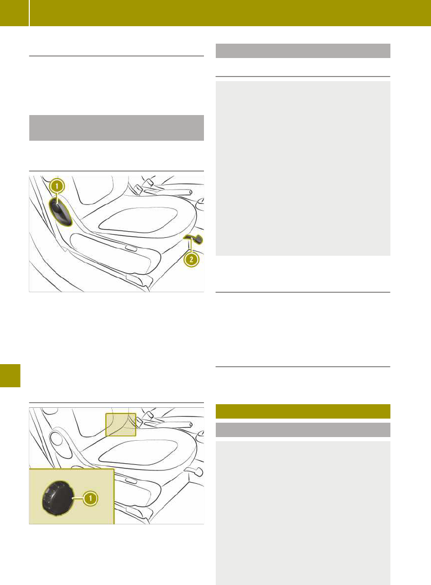
Closing the tailgate
X
Pull the tailgate up until it engages.
X
Press the & button on the key.
The vehicle is locked.
Enlarging the boot: folding the seat
backrest forwards
Folding the seat backrest forwards
(using the lever)
Seat with a lever
X
Lift lever ; and slide the front
passenger seat to its rearmost position.
X
Pull lever : forwards.
X
Fold the seat backrest forwards at the
same time.
Folding the seat backrest forwards
(using the handwheel)
Seat with a handwheel
X
Turn handwheel : forward.
Folding back the seat backrest
Please note
G
WARNING
If the seat backrest is not engaged, it may
fold forwards, e.g. during braking or in
the event of an accident.
R
As a result, a backrest which is not
engaged would press you into the seat
belt. The seat belt cannot perform its
intended protective function and could
additionally cause injury.
R
The backrest cannot restrain objects or
loads in the boot.
This poses an increased risk of injury.
Before every journey, make sure that the
backrest is engaged as described.
Folding back the seat backrest (using
the lever)
X
Pull lever :.
X
Push the seat backrest back at the same
time until it engages.
Folding back the seat backrest (using
the handwheel)
X
Turn handwheel : backwards.
Using the boot separator
Fitting the boot separator
G
WARNING
On its own, the boot cover cannot secure
or restrain heavy objects, items of lug-
gage and heavy loads. You could be hit by
an unsecured load during sudden
changes in direction, braking or in the
event of an accident. There is an
increased risk of injury or even fatal
injury.
Always store objects so that they cannot
be flung around. Secure objects, luggage
or loads against slipping or tipping over,
152
Using the boot separator
>> Loading and stowing.

e.g. by using lashing material, even if
you are using the boot cover.
For easier fitting, fold the front passenger
seat backrest forwards.
X
smart EQ fortwo: open the upper and
lower tailgate.
X
smart EQ fortwo cabrio: open the lower
tailgate.
X
smart EQ fortwo cabrio: fold the rear soft
top up.
X
Hold boot separator : with the luggage
net bag in the direction of the vehicle
interior in the boot.
X
Insert boot separator : into bracket ;
on the right side.
X
Slide handle ? to the right and hold.
X
Insert boot separator : into bracket ;
on the left side.
X
Release handle ?.
Boot separator : snaps into place.
X
Secure the luggage net bag with the Vel-
cro fasteners.
If boot separator : is not required and no
subwoofer is installed, it can be attached to
brackets =.
Hooking and unhooking the boot sep-
arator
X
Grip boot separator : in the middle and
pull it back.
X
Hook the boot separator into left and
right rear brackets A.
Removing/fitting the charging cable
bag
Removing the charging cable bag
X
Turn both buttons : to the left.
The buttons are released from the
anchorage.
X
Fold the charging cable bag to the left.
The Velcro fasteners under the charging
cable bag are detached.
X
Remove snap hook ;.
Removing/fitting the charging cable bag
153
>> Loading and stowing.
Z

Installing the charging cable bag
X
Place the charging cable bag with its side
resting on the engine compartment cover
and then position it on the side trim.
X
Position the charging cable bag in a ver-
tical position.
Take hold of the Velcro fasteners beneath
the charging cable bag.
X
Push both buttons : into the anchorage
and turn them to the right.
X
Secure snap hook ;.
154
Removing/fitting the charging cable bag
>> Loading and stowing.

Useful information
The engine compartment in the smart is
located at the rear, below the boot. Service
fluid reservoirs are located under the ser-
vice cover at the front.
When working on the vehicle, always com-
ply with all safety regulations. Always
have work in the engine compartment car-
ried out at a qualified specialist workshop.
Removing/fitting the subwoofer
Removing the subwoofer
X
Release quick-release fastener : in the
direction of the arrow.
X
Reach into the recess on the quick-
release fastener.
X
Detach, tilt and pull the subwoofer to the
right.
X
Pull out the connector.
Fitting the subwoofer
X
Insert the connector.
X
Place the subwoofer at the base of the
side trim.
X
Turn quick-release fastener : upwards.
X
Press the bracket into the recess in side
trim ;.
X
Turn quick-release fastener : clock-
wise.
Opening and closing the service cover
Please note
G
WARNING
If the service cover is not locked, it may
come loose during driving and block your
view or endanger other road users. There
is a risk of an accident and injury.
Therefore, make sure that the service
cover is locked before driving off.
G
WARNING
If the windscreen wipers start to move
when the service cover is open, you could
become caught up in the wiper rods.
There is a risk of injury.
Always switch off the windscreen wipers
and the ignition before you open the ser-
vice cover.
!
To ensure unhindered air intake, com-
pletely remove any dirt or snow from the
ventilation slots above the service cover.
The vehicle must be secured against rolling
away.
On vehicles with a lockable service cover,
the service cover must be unlocked before it
is opened.
Opening and closing the service cover
155
>> Maintenance and care.
Z

Unlocking the service cover
X
Insert the tip of the key into the opening
of lock cover :.
X
Press the key to the right ; to lever up
the lock cover.
X
Remove the lock cover.
X
Insert the key into the lock and turn it
90° clockwise.
Opening the service cover
X
Pull both levers ; in the direction of the
arrow.
X
Lift service cover = at the front.
X
Pull service cover = slightly forwards
and lift upwards.
X
Carefully rest service cover =, still
attached to the straps, against the front
of the vehicle.
Closing the service cover
X
Lift service cover =.
X
Slide bars A on the left and right of the
service cover under the bars on wing ?.
X
Press service cover = downwards.
X
Press both levers ; backwards in the
direction of the arrow.
Locking the service cover
X
Insert the key into the lock and turn it to
position 1.
X
Insert lock cover : on the driver's side
and snap it into place.
156
Opening and closing the service cover
>> Maintenance and care.

Checking service products and top-
ping up
Please note
G
WARNING
Service product can be poisonous and
hazardous to health. There is a risk of
injury.
Observe the instructions on the respec-
tive original container when using, stor-
ing and disposing off service products.
Always store service products in the
sealed original container. Always keep
service products out of the reach of chil-
dren.
H
Environmental note
Dispose of service products in an envi-
ronmentally-responsible manner.
Also observe the information in the "Service
products" section (Y page 212).
Service products include the following:
R
coolant
R
brake fluid
R
windscreen washer fluid
R
climate control system refrigerant
Service products approved for smart:
http://bevo.mercedes-benz.com
Checking the coolant and topping up
Checking the coolant level
X
Stop the vehicle on a level surface.
X
Let the coolant cool down for at least
30 minutes.
X
Open the service cover. (Y page 155)
X
Check reservoir ; visually.
The fluid level must be between the MIN
mark and the MAX mark.
Topping up the coolant
G
WARNING
The cooling system is pressurised when
the drive system is at normal operating
temperature. When you open the cap, you
could be scalded by hot coolant spraying
out. There is a risk of injury.
Let the drive system cool down before you
open the cap. Wear protective gloves and
eye protection when opening. Open the
cap slowly to relieve pressure.
!
Add only coolant that has been pre-
mixed with the desired antifreeze protec-
tion. You could otherwise damage the
engine.
You can find additional notes on the
coolant in the following places:
R
in the Mercedes-Benz Specifications
for Service Products, MB BeVo 310.1
-
on the internet at
http://bevo.mercedes-benz.com
-
on the Mercedes-Benz BeVo app
R
at a qualified specialist workshop
If antifreeze/corrosion inhibitor is present
in the correct concentration, the boiling
point of the coolant during operation is
approximately 130 †.
The antifreeze/corrosion inhibitor concen-
tration in the engine cooling system should
be 50% (antifreeze protection down to
-37 †). This will protect the engine cooling
system against freezing down to approx-
imately -25 †.
X
Cover cap : of coolant expansion
tank ; with a cloth.
X
Turn the cap slowly one half turn. If nec-
essary, allow excess pressure to escape.
X
Turn the cap further and remove it.
X
Top up the coolant to the MAX level.
Checking service products and topping up
157
>> Maintenance and care.
Z

X
Replace the cap and tighten it as far as it
will go.
X
Close the service cover. (Y page 155)
i
See "Technical data" for information on
recommended coolants.
Topping up the washer fluid
G
WARNING
Windscreen washer concentrate is highly
flammable. If it comes into contact with
hot components in the front compart-
ment, it may ignite. There is a risk of fire
and injury.
Make sure that windscreen washer con-
centrate is not spilled next to the filler
neck.
X
Open the service cover. (Y page 155)
X
Pull cap : upwards at the tab.
X
If available, pull the removable nozzle up
as far as the stop.
X
Top up with washer fluid.
X
If available, push the removable nozzle
down and push it inside.
X
Replace and tightly screw on cap :.
X
Close the service cover. (Y page 155)
i
See "Technical data" for information on
windscreen washer fluid and antifreeze.
Checking wheels and tyres
G
Warning
A flat tyre severely impairs the driving,
steering and braking characteristics of
the vehicle. There is a risk of an accident.
Do not drive with a flat tyre. Immediately
replace the flat tyre with your spare
wheel, or consult a qualified specialist
workshop.
G
WARNING
Damaged tyres can cause tyre inflation
pressure loss. As a result, you could lose
control of your vehicle. There is a risk of
accident.
Check the tyres regularly for signs of
damage and replace any damaged tyres
immediately.
G
WARNING
If there is insufficient tyre tread, the tyre
traction will decrease. The tyre tread can
no longer dissipate water. This increases
the risk of aquaplaning on a wet road
surface, especially when the vehicle's
speed is not adapted to the road condi-
tions. There is a risk of an accident.
If the tyre pressure is too high or too low,
tyres may wear differently at different
points of the tyre tread. Regularly check
the tyre tread depth and the condition of
the tread across the whole width of all
tyres, therefore.
Minimum tyre tread depth on:
R
Summer tyres: 3 mm
R
M+S tyres: 4 mm
For safety reasons, have the tyres
replaced before the legally specified
minimum tread depth is reached.
!
If you cannot avoid driving over obsta-
cles, e.g. kerbs, do so slowly and at an
obtuse angle only. You could otherwise
damage the wheel rims and tyres.
158
Checking wheels and tyres
>> Maintenance and care.

Modification work on the brake system and
wheels is not permitted. The use of spacers
or brake dust shields is not permitted. This
invalidates the general operating permit
for the vehicle.
Check the wheels and tyres for damage at
least once a month, as well as after driving
off-road or on poorly surfaced roads.
Run-in new tyres at moderate speeds for
the first 100 km. The tyres only attain their
maximum performance after this distance.
Vibrations, audible noises and unusual
handling characteristics, e.g. pulling to one
side, can indicate damage to wheels or
tyres.
If you suspect a tyre defect:
X
Reduce vehicle speed.
X
Stop the vehicle as soon as possible.
X
Check the wheels and tyres for damage.
If you find no signs of damage, have the
wheels and tyres checked at a specialist
workshop.
Changing a wheel
Please note
G
WARNING
Interchanging the front and rear wheels
if the wheels or tyres have different
dimensions may severely impair the
driving characteristics. The service brake
or wheel suspension components may
also be damaged. There is a risk of an
accident.
Rotate front and rear wheels only if the
wheels and tyres are of the same dimen-
sions.
G
WARNING
Exceeding the stated tyre load-bearing
capacity and the approved maximum
speed could lead to tyre damage or the
tyre bursting. There is a risk of accident.
Therefore, only use tyre types and sizes
approved for your vehicle model. Observe
the tyre load rating and speed rating
required for your vehicle.
G
WARNING
If you fit wheels and tyres with incorrect
dimensions, the service brake or wheel
suspension components may be damaged.
There is a risk of an accident.
Always replace wheels and tyres with
ones that comply with the specifications
of the original part.
When replacing wheels, pay attention to
the:
R
designation
R
type
When replacing tyres, pay attention to
the:
R
designation
R
manufacturer
R
type
!
To prevent damage, smart recommends
having the wheel changed at a qualified
specialist workshop.
!
On vehicles fitted with a tyre pressure
monitor, electronic components are loca-
ted in the wheel.
Tyre-fitting tools should not be applied
in the area of the valve, since this could
damage the electronic components.
Only have tyres changed at a qualified
specialist workshop.
!
Only position a suitable jack on the
jacking point intended for the purpose.
Only raise the vehicle briefly to change
the wheel. Make sure that there are no
persons in the vehicle and that it is on a
suitable surface. Secure the vehicle with
wheel chocks and apply the parking
brake.
Interchanging front and rear wheels or
tyres of differing dimensions can render
the general operating permit invalid.
Rules for selecting new tyres
!
For safety reasons, smart recommends
that you only use wheels and tyres which
smart has specifically approved for your
Changing a wheel
159
>> Maintenance and care.
Z

vehicle. These are specially adapted to
the systems, such as ABS or ESP
®
.
Only use tyres and wheels tested and
recommended by smart. Certain charac-
teristics, such as handling, vehicle noise
emissions, fuel consumption, etc. may
otherwise be adversely affected. Dimen-
sional variations and altered tyre defor-
mation when driving under load may also
cause the tyres to come into contact with
the vehicle body and axle components.
This may result in damage to the tyre or
the vehicle.
smart is not responsible for any damage
caused by using tyres and wheels other
than those which have been tested and
recommended.
You can obtain information about tyres
and wheels from any qualified specialist
workshop, e.g. a smart Centre.
The service life of tyres depends on various
factors, including the following:
R
driving style
R
tyre pressure
R
mileage
Observe the following rules for selecting
new tyres:
R
observe country-specific regulations
which stipulate or recommend a certain
tyre type for the vehicle.
R
only fit tyres and wheels of the same
type and make.
R
only tyres of the same size may be used
on a single axle (left/right).
R
only use tyres of the same type (summer
tyres, all-season tyres, winter tyres).
R
only use wheel-tyre combinations
approved by smart.
R
do not wear tyres out too much. This oth-
erwise significantly reduces the traction
on wet roads (aquaplaning).
R
replace tyres after six years at the latest.
R
the use of a specific tyre type in certain
regions and areas of operation can be
highly beneficial.
i
Recommended tyre pressures for vari-
ous operating states can be found on the
tyre pressure table on the driver's side
door pillar (B-pillar).
You can find further information regarding
tyres and wheels at specialist tyre retail-
ers, at qualified specialist workshops and
at any smart Centre.
Preparing to change a wheel
The vehicle tool tray is located under the
glove compartment.
X
Stop the vehicle on solid, non-slippery
and level ground.
X
Apply the parking brake.
X
Position the front wheels to point
straight ahead.
X
Shift the transmission to position j.
X
Switch off the engine.
X
Remove the key from the ignition lock.
X
Secure the vehicle against rolling away.
Removing a wheel
G
WARNING
If you do not position the jack correctly
at the appropriate jacking point of the
vehicle, the jack could tip over with the
vehicle raised. There is a risk of injury.
Only position the jack at the appropriate
jacking point of the vehicle. The base of
the jack must be positioned vertically,
directly under the jacking point of the
vehicle.
!
Do not place wheel bolts in sand or dirt.
The threads of the wheel bolts and wheel
hubs could otherwise be damaged when
the bolts are tightened.
!
Position a suitable jack only on the
jacking points intended for this purpose.
Never position the jack on the high-volt-
age battery. Do not jack up the vehicle on
the high-voltage battery. There is other-
wise a risk of damaging the high-voltage
battery.
Also observe the notes in the "Changing a
wheel" section.
160
Changing a wheel
>> Maintenance and care.

Warning stickers
Always pay attention to the instructions
and safety notes on "Changing a wheel"
(Y page 159).
Vehicles with steel wheels and hub caps:
X
Using both hands, grasp two hub cap
openings and remove the hub cap.
Vehicles with steel wheels and hub cap
cover:
X
Remove the hub cap cover.
:
Wheel wrench
X
Using wheel wrench : loosen the wheel
bolts by about one turn. Do not unscrew
the wheel bolts completely.
;
Jack
=
Reinforced area for the jacking points
Jack ; may only be positioned on the
reinforced area intended for this purpose
for jacking points =.
The vehicle may be damaged if jack ; is
positioned at another point on the sill.
=
Reinforced area for the jacking points
?
Triangular indentation
A
Outer covering of the sill
Changing a wheel
161
>> Maintenance and care.
Z

!
To prevent damage, smart recommends
having the wheel changed at a qualified
specialist workshop.
The reinforced areas for jacking points =
are located behind the front wheels and in
front of the rear wheels. They can be recog-
nised by triangular indentations ? on the
vehicle.
Jack ; may only be positioned on the
reinforced areas for jacking points = on
the sill and not on the outer covering of sill
A.
X
Search for the reinforced area for jacking
points = which is found approx. 7 cm
behind the sill at triangular indenta-
tions ?.
X
Position jack ; under the corresponding
reinforced area for jacking points =.
X
Set the foot of the jack up vertically with
respect to the reinforced area for the
jacking points on the vehicle.
X
Make sure that the jack is correctly posi-
tioned so that the vehicle cannot slip.
X
Raise the vehicle using the jack until the
tyre is a maximum of 3 cm off the ground.
X
Unscrew and remove the wheel bolts.
X
Remove the wheel.
Fitting a wheel
G
WARNING
The wheels could come loose if the wheel
bolts or wheel nuts are not tightened to
the prescribed tightening torque. There
is a risk of an accident.
Ensure that the wheel bolts or wheel nuts
are tightened to the prescribed tighten-
ing torque.
If you are not sure, do not move the vehi-
cle. Contact a qualified specialist work-
shop and have the tightening torque
checked immediately.
The tightening torque must be 105 Nm.
After travelling approx. 500 km, check the
tightening torque and retighten if neces-
sary.
G
WARNING
If you tighten the wheel bolts or wheel
nuts when the vehicle is raised, the jack
could tip over. There is a risk of injury.
Only tighten the wheel bolts or wheel
nuts when the vehicle is on the ground.
!
When changing a wheel, only use wheel
bolts which have been approved for
wheel rims and the vehicle.
Always pay attention to the instructions
and safety notes on "Changing a wheel"
(Y page 159).
Fit tyres with a specified direction of rota-
tion only according to their direction of
rotation. An arrow on the sidewall of the
tyre indicates its correct direction of rota-
tion.
X
Clean the wheel and wheel hub contact
surfaces.
X
Push the wheel onto the wheel hub and
press it on.
X
Screw in the wheel bolts up to the cone.
X
Make sure that they sit securely on the
cone.
162
Changing a wheel
>> Maintenance and care.

X
Lower the vehicle all the way.
X
Remove the jack.
X
Tighten the wheel bolts evenly in a
crosswise pattern in sequence indica-
ted : to ?. The tightening torque must
be 105 Nm.
X
Check the recommended tyre pressure
and adjust if necessary.
After travelling approx. 500 km, check the
tightening torque and retighten if neces-
sary.
i
Vehicles with tyre pressure control sys-
tem: all fitted wheels must be equipped
with functioning sensors.
Vehicles with steel wheels and hub caps:
X
Fit hub cap A such that valve B does
not become trapped.
X
Press the hub cap evenly onto the wheel
with both hands until you hear the hub
cap engage.
X
Check to make sure the hub cap is seated
securely on the wheel.
Vehicle with steel wheels and wheel hub
covers:
X
Fit the hub cap cover.
Storing wheels
X
Store wheels in a cool, dry and dark place
when not in use.
X
Protect against oil and grease.
Using the tyre pressure monitor
Useful information
It is the driver's responsibility to set the
tyre pressure to the recommended cold tyre
pressure suitable for the operating situa-
tion.
The tyre pressure monitor issues a warning
when the pressure drops in one or more of
the tyres.
The tyre pressure monitor works properly
only if sensors are present in all four tyres,
and after the monitor has learned the cor-
rect tyre pressure for the current operating
situation. This occurs automatically in
most situations, but may also be specified
after restarting the tyre pressure monitor.
Before restarting, check the tyres for the
recommended tyre pressure.
The tyre pressure monitor does not provide
a warning in the following cases:
R
even loss of pressure on multiple tyres
R
sudden loss of tyre pressure, e.g. due to
penetration by a foreign body
R
incorrectly set tyre pressure
The tyre pressure monitor has a yellow
warning lamp in the instrument cluster for
indicating a pressure loss or malfunction.
Restarting the tyre pressure monitor
(on-board computer with a mono-
chrome display)
X
Set the tyre pressure of all tyres to the
recommended value.
X
On the multifunction lever, press the
´ button repeatedly until the °
and h symbols are displayed in the
instrument cluster display.
X
Press and hold the a button on the
multifunction lever.
The ° and h symbols flash in the
instrument cluster display for approx-
Using the tyre pressure monitor
163
>> Maintenance and care.
Z

imately five seconds. The two symbols
then light up.
The tyre pressure monitor is restarted.
Restarting the tyre pressure monitor
(on-board computer with colour dis-
play)
X
Set the tyre pressure of all tyres to the
recommended value.
X
Select Settings > Tyre pressure moni‐
tor in the on-board computer.
The Tyre pressure monitor Adopt cur‐
rent pressures as new reference
values? message appears in the display.
X
Select Yes and press a to confirm.
The display shows the Tyre pressure
monitor restarted message.
If the Tyre pressure monitor restarted
message does not appear after five seconds,
restart the tyre pressure monitor again.
Checking the tyre pressures
Please note
G
WARNING
Underinflated or overinflated tyres pose
the following risks:
R
the tyres may burst, especially as the
load and vehicle speed increase.
R
the tyres may wear excessively and/or
unevenly, which may greatly impair
tyre traction.
R
the driving characteristics, as well as
steering and braking, may be greatly
impaired.
There is a risk of an accident.
Observe the recommended tyre pressure
and check the tyre pressure of all the
tyres:
R
at least every two weeks
R
when the load changes
R
before embarking on a longer journey
R
for changed operating conditions, e.g.
off-road driving
If necessary, correct the tyre pressure.
G
WARNING
If you mount unsuitable accessories onto
tyre valves, the tyre valves may be over-
loaded and malfunction, which can cause
tyre pressure loss. Aftermarket tyre pres-
sure monitoring systems will cause the
tyre valve to remain open. This can also
result in tyre pressure loss. There is a
risk of an accident.
Only screw standard valve caps or valve
caps specifically approved by smart for
your vehicle onto the tyre valve.
G
WARNING
If the tyre pressure drops repeatedly, the
wheel, valve or tyre may be damaged.
Tyre pressure that is too low may result
in a tyre blow-out. There is a risk of acci-
dent.
R
Check the tyre for foreign objects.
R
Check whether the wheel is losing air
or the valve is leaking.
If you are unable to rectify the damage,
contact a qualified specialist workshop.
H
Environmental note
Check the tyre pressure regularly, at
least every 14 days.
164
Checking the tyre pressures
>> Maintenance and care.

The table with the recommended tyre pres-
sure for various operating conditions can
be found on the driver's side door pillar
(B-pillar).
The tyre pressure table may also state air
pressures for different load conditions.
These are defined in the table as different
numbers of passengers and amounts of lug-
gage. The actual number of seats may differ
from this.
If a tyre size precedes a tyre pressure, the
tyre pressure information following is only
valid for that tyre size. If tyre sizes are not
specified, the tyre pressures stated on the
tyre pressure table apply for all approved
tyres.
Checking and correcting the tyre
pressure manually
Only check the tyre pressure once the tyres
have cooled down.
X
Drive the vehicle less than 2 km.
X
Park the vehicle away from direct sun-
light for at least three hours.
X
Check the tyre pressure with a suitable
tyre pressure gauge.
X
If necessary, adjust the tyre pressure.
X
Restart the tyre pressure monitor.
Using winter tyres
G
WARNING
M+S tyres with a tyre tread depth of less
than 4 mm are not suitable for use in
winter as they do not provide sufficient
traction. There is a risk of accident.
M+S tyres with a tread depth of less than
4 mm must be replaced.
At temperatures below +7 †, summer tyres
lose elasticity and therefore traction and
braking power. Change the tyres on your
vehicle therefore to winter tyres or all-sea-
son tyres marked with M+S. Using summer
tyres at very cold temperatures could cause
tears to form, thereby damaging the tyres
permanently. smart cannot accept respon-
sibility for this type of damage.
Have the vehicle winterproofed at a quali-
fied specialist workshop at the onset of
winter.
X
At low temperatures, use only winter
tyres marked with M+S.
X
When road conditions are wintry, use
M+S tyres with the additional i snow-
flake symbol.
These tyres allow driving safety systems,
e.g. ABS, to function optimally in the
winter.
X
Use M+S tyres of the same make and tread
on all wheels.
X
When driving with M+S tyres, observe the
specified maximum permissible speed.
X
Use only tyre types and sizes approved
for smart.
X
When using tyres with a specified direc-
tion of rotation, observe the arrow on the
sidewall indicating the tyre's direction of
rotation.
After fitting M+S tyres:
X
Check the tyre pressure.
X
Restart the tyre pressure monitor.
X
If M+S tyres with a lower maximum per-
missible speed than that of the vehicle
are fitted, affix an appropriate warning
label in the driver's field of vision. Using
the limiter, restrict the speed to the max-
imum permissible speed for M+S tyres.
Using snow chains
G
WARNING
If you have fitted snow chains to the
front wheels, they may scrape against the
vehicle body or chassis components. This
could cause damage to the vehicle or the
tyres. There is a risk of an accident.
To avoid hazardous situations:
R
never fit snow chains on the front
wheels
R
fit snow chains to the rear wheels in
pairs.
!
Vehicles with steel wheels: if you fit
snow chains on steel wheels, you may
damage the hub caps. Remove the hub
Using snow chains
165
>> Maintenance and care.
Z

caps from the relevant wheels before fit-
ting the snow chains.
For safety reasons, smart recommends that
you only use snow chains that have been
specially approved for your vehicle by
smart. Further information can be obtained
at a smart Centre or a qualified specialist
workshop.
X
Observe country-specific regulations.
X
Use only snow chains approved for smart.
X
Fit snow chains on both rear wheels.
X
Use snow chains only on snow-covered
roads.
X
When driving with snow chains fitted, do
not exceed the maximum permissible
speed of 50 km/h.
Changing the window wiper blades
Please note
G
WARNING
If the windscreen wipers begin to move
while you are changing the wiper blades,
you can be trapped by the wiper arm.
There is a risk of injury.
Always switch off the windscreen wipers
and ignition before changing the wiper
blades.
!
Never open the service cover or tailgate
if a wiper arm has been folded away from
the windscreen or rear window. Never
fold a wiper arm without a wiper blade
back onto the windscreen or rear window.
Hold the wiper arm firmly when you
change the wiper blade. If you release the
wiper arm without a wiper blade and it
falls onto the window, the window may be
damaged by the force of the impact.
Changing the window wiper blades on
the windscreen
X
Fold the wiper arm away from the wind-
screen.
X
Release tab ; of bracket ? must be
pressed towards windscreen 3. The
catch tab is released from the bracket
and the wiper blade can be pulled away
from the wiper arm.
X
Slide window wiper blade : in the direc-
tion of arrow 5 until the securing hook
for the window wiper blade is revealed.
X
Remove the window wiper blade.
X
Slide new window wiper blade : in the
direction of arrow 4 onto mounting =
of wiper arm ;.
The window wiper blade snaps into place.
X
Check that the window wiper blade is
positioned correctly.
X
Carefully fold wiper arm ; onto the
windscreen.
166
Changing the window wiper blades
>> Maintenance and care.

Changing the rear window wiper blade
(smart EQ fortwo)
X
Remove the key from the ignition lock.
X
Fold wiper arm : away from the rear
window until you hear it engage.
X
Unscrew window wiper blade ; in the
direction of the arrow until it is released
from the retainer on the wiper arm.
X
Pull out window wiper blade ;.
X
Press new window wiper blade ; onto
wiper arm : until it engages.
X
Check that window wiper blade ; is
positioned correctly.
X
Fold wiper arm : back onto the rear
window.
Cleaning the vehicle
Useful information
Regular care maintains the appearance and
quality of the vehicle over time.
Observe the following when cleaning and
caring for the vehicle:
X
Do not clean the engine.
X
Do not clean the vehicle whilst charging.
X
Use soft, moist cloths.
X
Use care products and cleaning agents
recommended and approved for smart.
X
Do not use acidic cleaning agents.
X
In winter, carefully remove road salt as
soon as possible.
Cleaning the vehicle exterior
Washing in an automatic car wash or
washing by hand
Preparing the vehicle for cleaning
G
WARNING
Braking efficiency is reduced after the
vehicle has been washed. There is a risk
of an accident.
After washing the vehicle, brake carefully
while paying attention to the traffic con-
ditions in order to restore full braking
efficiency.
X
Close the side windows completely.
X
Switch off the climate control blower.
X
Turn the windscreen wipers to position
g.
Notes on care of matt paintwork
!
The following can give the paint a
glossy appearance and thus reduce the
matt effect:
R
Rubbing hard with unsuitable agents
R
Washing the vehicle in direct sunlight
!
Only use automatic car washes which
correspond to the latest technological
standards. Never use wash programs
which finish by treating the vehicle with
hot wax.
!
Never use paint cleaner, buffing or pol-
ishing products, or gloss preserver, e.g.
wax, for the purpose of paintwork care.
These products are only suitable for
high-gloss surfaces. Their use on vehi-
cles with matt paintwork leads to consid-
erable surface damage or, more specifi-
cally, to shiny, spotted areas.
Always have paintwork repairs carried
out at a qualified specialist workshop.
!
Never polish the vehicle or the light
alloy wheels. Polishing makes the paint-
work shiny.
If your vehicle has a clear matt finish,
observe these notes. By doing so, you can
avoid paintwork damage due to incorrect
handling.
Cleaning the vehicle
167
>> Maintenance and care.
Z

Washing in an automatic car wash
X
Prepare the vehicle for cleaning.
X
Remove excess dirt.
X
Drive through the automatic car wash.
X
Remove wax from the front windscreen
and the wiper blades.
i
If the windscreen wipers leave smears
after the vehicle has passed through the
car wash, this may be caused by wax or
other residue. This residue can be
removed with washer fluid.
Washing by hand
X
Locate a washing bay equipped for hand-
washing.
X
Prepare the vehicle for cleaning.
X
Apply mild cleaning agent with a soft
vehicle sponge.
X
Thoroughly hose the vehicle with a gen-
tle jet of water; do not point the water jet
directly towards the air inlet grille.
X
Dry the vehicle off with a chamois.
Cleaning with a high-pressure cleaner
G
WARNING
The water jet of circular-jet nozzles (dirt
grinders) can cause damage not visible
from the outside to tyres or chassis com-
ponents. Components damaged in this
way can unexpectedly fail. There is a risk
of an accident.
Do not use high-pressure cleaners with
circular-jet nozzles to clean the vehicle.
Have damaged tyres or chassis compo-
nents replaced immediately.
!
Always maintain a distance of at least
30 cm between the vehicle and the high-
pressure cleaner nozzle. Information
about the correct distance is available
from the equipment manufacturer.
Move the high-pressure cleaner nozzle
around when cleaning your vehicle.
Do not aim directly at any of the follow-
ing:
R
tyres
R
door gaps, roof gaps, joints etc.
R
electrical components
R
battery
R
plug-type couplings
R
light bulbs
R
seals
R
trim elements
R
ventilation slots
Damaged seals or electrical components
can lead to leaks or failures.
X
Prepare the vehicle for cleaning.
X
Maintain a distance of at least 30 cm
between the high-pressure cleaner noz-
zle and the vehicle.
X
Keep moving the nozzle whilst cleaning.
Cleaning the reversing camera
X
Clean camera lens : with water and a
soft cloth.
168
Cleaning the vehicle
>> Maintenance and care.

Cleaning the sensors
:
Active Brake Assist sensor
;
Parking aid sensors
X
Clean sensors with water, car shampoo
and a soft cloth.
Cleaning the wheels
G
WARNING
The water jet of circular-jet nozzles (dirt
grinders) can cause damage not visible
from the outside to tyres or chassis com-
ponents. Components damaged in this
way can unexpectedly fail. There is a risk
of an accident.
Do not use high-pressure cleaners with
circular-jet nozzles to clean the vehicle.
Have damaged tyres or chassis compo-
nents replaced immediately.
!
Do not use acidic wheel cleaning prod-
ucts to remove brake dust. This could
damage wheel bolts and brake compo-
nents.
!
Do not park up your vehicle for a long
period of time immediately after clean-
ing, particularly after cleaning the wheel
rim with wheel cleaner. Wheel cleaner
may lead to increased corrosion of the
brake discs and pads. You should there-
fore drive for a few minutes after clean-
ing. By heating up the brakes, the brake
discs and pads dry. The vehicle can then
be parked up for a long period of time.
X
Clean the wheels with an acid-free clean-
ing agent.
Cleaning the windows and windscreen
wipers
Cleaning the windows
G
WARNING
If the windscreen wipers are set in
motion when cleaning the windscreen or
wiper blades, you could become trapped.
There is a danger of injury.
Always switch off the windscreen wipers
and the ignition before cleaning the
windscreen or wiper blades.
X
Place the wiper arms in the vertical posi-
tion and fold them away from the win-
dow.
X
Clean the inside and outside of the win-
dows with a damp cloth and a cleaning
agent recommended for smart.
X
Clear deposits regularly from the wind-
screen and rear window to ensure that
water can drain unhindered.
Cleaning the window wiper blades
X
Place the wiper arms in the vertical posi-
tion and fold them away from the win-
dow.
X
Clean the window wiper blades with a
soft cloth.
X
Fold the wiper arms back into place.
Cleaning the panoramic roof (smart EQ
fortwo)
!
Only use cleaning agents or cleaning
cloths that are suitable for plastic lenses.
Unsuitable cleaning agents or cleaning
cloths could scratch or damage the plas-
tic panes of the panorama roof. Do not use
cleaning agents containing solvents
X
Apply mild cleaning agent for plastic
windows and wipe off with a moist
sponge.
Cleaning the vehicle
169
>> Maintenance and care.
Z

Cleaning the roof
Dry cleaning
X
Brush from the front to the back using a
soft brush.
Wet cleaning
X
Dry clean first.
X
Wash down with a soft brush or sponge
and lukewarm water.
X
Rinse with clean water.
Cleaning the soft top (smart EQ fortwo
cabrio)
Useful information
!
Never clean the soft top using a high-
pressure cleaner as water could other-
wise enter the vehicle interior.
!
Only clean the folding roof and the rear
soft top when they are closed.
Dry cleaning
X
Brush from the front to the back using a
soft brush.
Wet cleaning
X
Dry clean first.
X
Wash down with a soft brush or sponge
and lukewarm water.
X
Rinse with clean water.
Cleaning the exterior lighting
X
Apply mild cleaning agent for plastic
lenses and wipe off with a wet sponge.
Cleaning and caring for paintwork
!
Do not affix stickers to the painted sur-
face. Adhesive residue could damage the
paintwork.
X
Remove impurities immediately by rub-
bing carefully.
X
Soak insect remains with insect remover
and rinse off.
X
Soak bird droppings with water and rinse
off.
X
Use tar remover to remove tar stains.
X
Use silicone remover to remove wax.
X
Remove coolant, brake fluid, tree resin,
oils, fuels and greases by rubbing care-
fully with a cloth soaked in petroleum
ether or lighter fluid.
Cleaning the vehicle interior
Cleaning the displays
!
For cleaning, do not use any of the fol-
lowing:
R
alcohol-based thinner or petrol
R
abrasive cleaning agents
R
commercially-available household
cleaning agents
These may damage the display surface.
Do not put pressure on the display sur-
face when cleaning. This could lead to
irreparable damage to the display.
X
Switch off the display and let it cool
down.
X
Clean the display surface with a microfi-
bre cloth and cleaner for TFT or LCD dis-
plays.
X
Dry the display surface using a dry
microfibre cloth.
Cleaning the steering wheel and the
selector lever
X
Wipe off with a moist cloth, or use a
leather care agent recommended for
smart.
Cleaning the seat belts
G
WARNING
Seat belts may be severely weakened if
bleached or coloured. This may lead to
the seat belts, for example, tearing or
failing in an accident. There is an
increased risk of injury, possibly even
fatal.
Never bleach or colour seat belts.
!
Do not clean the seat belts using chemi-
cal cleaning agents. Do not dry the seat
170
Cleaning the vehicle
>> Maintenance and care.

belts at temperatures above 80 † or in
direct sunlight.
X
Clean the seat belts using only lukewarm
soapy water.
Cleaning and caring for seats
Please note
!
Do not use a microfibre cloth to clean
covers made of genuine leather or artifi-
cial leather. A microfibre cloth is too
aggressive and can damage the cover
when used frequently.
Regular care maintains the appearance and
feel of the seats over time.
Cleaning and caring for genuine leather
seat covers
X
Wet a cloth with water and clean the seat
covers. Do not allow the leather to become
soaked.
X
Wipe off with a dry cloth.
X
Apply a leather care agent recommended
for smart.
Cleaning synthetic leather seat covers
X
Wet a cloth with detergent water and
clean the seat covers.
Cleaning cloth seat covers
X
Wet a microfibre cloth with detergent
water.
X
Rub cloth covers with care, cleaning
entire sections of the cover.
X
Allow the seat to dry.
Cleaning DINAMICA seat covers
X
Wet a cloth with water.
X
Clean entire sections of the cover.
Cleaning the trim
Cleaning the plastic trim
G
WARNING
Care products and cleaning agents con-
taining solvents can cause surfaces in
the cockpit to become porous. This could
result in plastic parts breaking away
when the airbags are deployed. There is a
danger of injury.
Do not use care products and cleaning
agents containing solvents to clean the
cockpit.
!
Never attach the following to plastic
surfaces:
R
stickers
R
films
R
perfume oil container or similar
You could otherwise damage the plastic.
To maintain the appearance of high-quality
plastic surfaces, do not allow surfaces to
come into contact with cosmetics, insect
repellents or sun creams.
X
Clean the plastic trim with a damp cloth.
X
Use care products and cleaning agents
recommended for smart to remove heavy
soiling.
Cleaning the roof lining (smart EQ fortwo)
X
Remove heavy soiling using a soft brush
or a cleaning agent recommended for
smart.
Cleaning the carpets
X
Use carpet and textile cleaning agents
recommended for smart.
Cleaning the trim elements
!
Do not use solvent-based cleaning
agents such as tar remover, wheel clean-
ers, polishes or waxes. There is otherwise
a risk of damaging the surface.
X
Clean the trim elements with a moist
microfibre cloth.
X
Use care products and cleaning agents
recommended for smart to remove heavy
soiling.
Cleaning the vehicle
171
>> Maintenance and care.
Z

Observing service due dates
The ¯ and ° indicator lamps in the
instrument cluster display are reminders of
upcoming service due dates:
R
¯: minor service.
R
°: major service.
Monochrome display: the indicator lamp
flashes for a few seconds after the engine is
started. Depending on the operating condi-
tions of the vehicle, the time or distance
remaining until the service is due, is also
displayed.
The service interval is based on normal
operation of the vehicle. Observe the fol-
lowing if the vehicle is operated under
arduous conditions or increased loads, e.g.
regular city driving with frequent inter-
mediate stops:
X
Carry out service work more often than
specified by the service interval.
X
Check the tyres more frequently.
Current information on the type of service
can be obtained at a smart centre or a
qualified specialist workshop.
Parking up the vehicle
!
Please note that if the vehicle is not
used for prolonged periods, vehicle dam-
age may occur and the battery may dis-
charge or become damaged.
X
Visit a qualified specialist workshop for a
consultation.
172
Parking up the vehicle
>> Maintenance and care.

Securing the vehicle in the event of
an accident or a breakdown
Securing the vehicle
!
When a tyre is damaged, the danger
area must be kept clear of all persons.
X
Stop the vehicle away from traffic on
solid, non-slippery ground.
X
Switch on the hazard warning lights.
X
Turn the front wheels to the straight-
ahead position.
X
Switch off the engine.
X
Passengers should leave the vehicle.
X
Secure the vehicle against rolling away.
X
Set up the warning triangle.
In the event of a flat tyre, without TIREFIT
the vehicle cannot be made roadworthy
again using the on-board equipment. No
emergency call can be made via the smart
Audio-System. The vehicle owner and the
driver of the vehicle are responsible for
equipping the vehicle with an appropriate
breakdown kit and seeking assistance in
the event of a breakdown.
Switching the hazard warning lamps
on and off
When the hazard warning lamps are
switched on, all the turn signal lamps flash.
The hazard warning lamps automatically
switch on in the following cases:
R
an airbag is deployed.
R
the vehicle decelerates rapidly from a
speed of above 70 km/h and comes to a
standstill.
The hazard warning lamps switch off auto-
matically if the vehicle reaches a speed of
above 10 km/h again after a full brake
application.
X
To switch on the hazard warning lamps
manually: press button :.
Operating the emergency assistance
system
Useful information
For Russia only:
The emergency assistance system is there
to rescue you and others in an emergency.
Should the driver arrive at the scene of an
accident, or feel unwell, an emergency call
can be initiated. The emergency call must
not be deployed in the case of a breakdown
or a similar, non-dangerous situation.
The emergency assistance system can help
to radically reduce the time between an
accident and the arrival of the emergency
services. The requirement is a stable mobile
phone connection; network coverage can
depend on the region.
If there is no safety risk, in the event of an
accident the vehicle occupants should
remain in the vehicle after initiating an
emergency call.
The emergency assistance system has a
separate battery. The battery only func-
tions within a temperature range of -20 †
to 85 †. The battery must be replaced every
four years. Always have work on the bat-
tery carried out at a qualified specialist
workshop.
Method of operation
After an emergency call has been initiated,
the emergency call centre will ascertain if
assistance is required on location.
Securing the vehicle in the event of an accident or a breakdown
173
>> Dealing with accidents and breakdowns.

In the event of an emergency, accident data
is forwarded to a public emergency call
centre.
The data transferred includes:
R
GPS/GLONASS position data
R
Direction of travel
R
Time of initiation
This allows measures for rescue, recovery
or towing away to be initiated quickly.
The emergency assistance system consists
of a loudspeaker, the control panel and the
telecommunication system. The control
panel is located in the overhead control
panel.
:
Automatic emergency call indicator
lamp
;
Microphone
=
SOS button
?
Call and reception status indicator lamp
Using test mode
In test mode, the driver can check if the
emergency assistance system is working.
To do this, a voice message from the driver
is recorded and the test result is transmit-
ted to the emergency call centre.
X
Briefly press SOS button = several times
within five seconds.
X
Wait for 25 seconds.
X
Briefly press SOS button = three times
within ten seconds.
A tone sounds. Microphone ; records for
ten seconds.
X
Speak any message.
A signal sounds after 25 seconds. The
recorded message is played back via the
loudspeaker.
X
If the voice message is correctly played
back, press and hold SOS button = for
five seconds.
Indicator lamp ? flashes green slowly.
or
X
If the voice message is incorrectly played
back or not played back at all, press SOS
button = three times within three sec-
onds.
Indicator lamp ? flashes red slowly for
five seconds.
Automatic emergency call
Indicator lamp : shows if an automatic
emergency call can be initiated.
If airbags are deployed, the emergency
assistance system automatically notifies an
emergency centre.
i
The automatic emergency call is opera-
tional as standard.
Triggering an emergency call manually
Manually initiating an emergency call as a
person involved in an accident:
X
Press and hold SOS button = for three
seconds.
An emergency call is made.
Manually initiating an emergency call after
witnessing an accident:
X
Press SOS button = five times within ten
seconds.
The emergency call centre is informed of
the accident.
174
Securing the vehicle in the event of an accident or a breakdown
>> Dealing with accidents and breakdowns.

Securing the vehicle against rolling
away
Securing on level ground
X
When changing a wheel, place chocks or
other suitable items under the front and
rear of the wheel that is diagonally oppo-
site the wheel you wish to change.
Securing on a downhill gradient
X
Place wheel chocks or other suitable
items in front of the wheels of the front
and rear axle.
Using the warning triangle
Removing the warning triangle
Warning triangle : is secured behind the
driver's seat backrest with a Velcro fas-
tener.
X
Fold the driver's seat forwards.
X
Remove warning triangle :.
Setting up the warning triangle
X
Fold feet 3 out to the side.
X
Pull side reflectors 2 upwards to form a
triangle.
X
Connect the reflectors using upper stud
1.
X
Place the warning triangle at a suitable
distance.
Securing the vehicle in the event of an accident or a breakdown
175
>> Dealing with accidents and breakdowns.
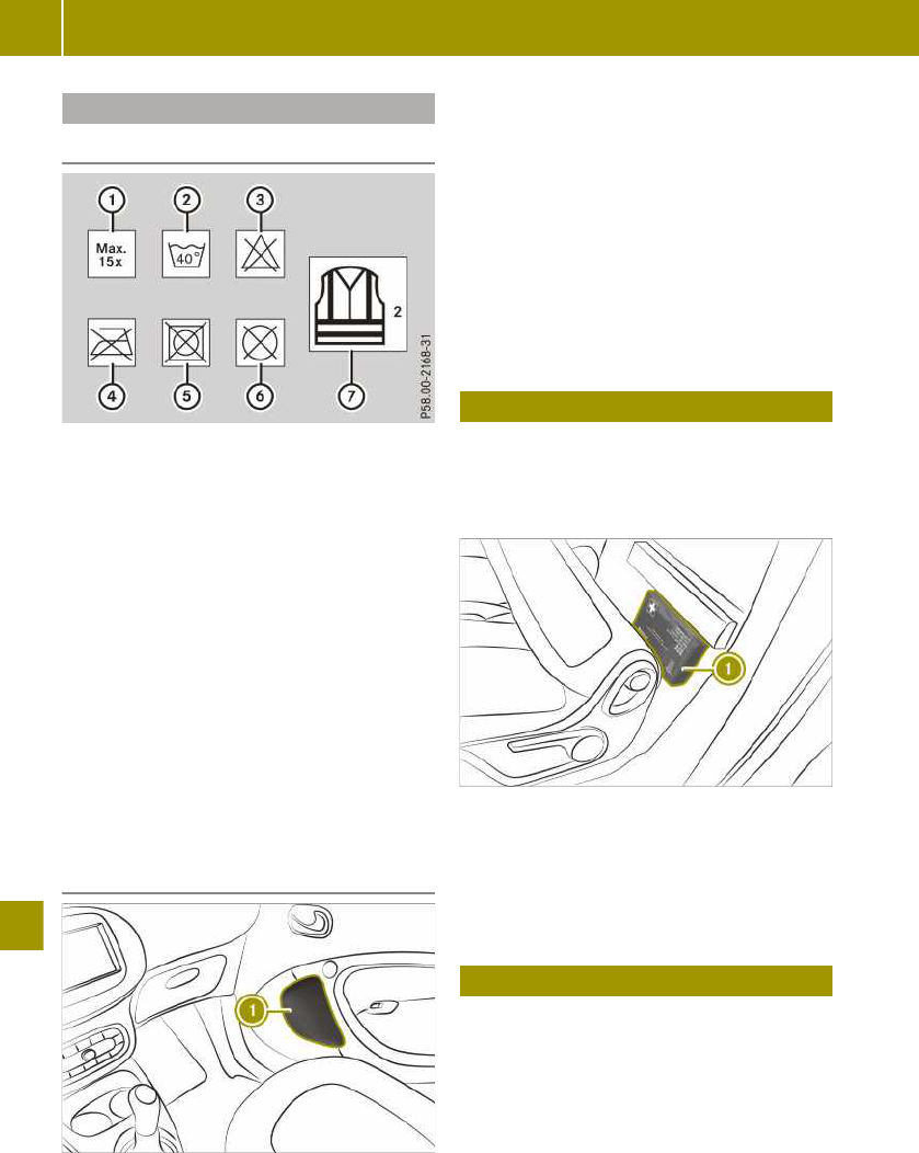
Using a reflective safety jacket
Notes on reflective safety jackets
:
Maximum number of washes
;
Maximum wash temperature
=
Do not bleach
?
Do not iron
A
Do not use a tumble dryer
B
Do not dry-clean
C
This is a class 2 jacket
The reflective safety jacket only meets the
requirements defined by the legal standard
if it is the right size and fully closed when
in use.
Replace the reflective safety jacket:
R
if it is damaged or there is irremovable
dirt on the reflective stripes
R
if you exceed the maximum number of
washes
R
if the fluorescence has faded
Removing the reflective safety jacket
The reflective safety jacket is located in
stowage compartment : of the front-
passenger door. Reflective safety jackets
can also be stored in the rear door stowage
compartments.
X
To remove: take out the safety jacket bag
containing the reflective safety jacket.
X
Open the safety jacket bag and take out
the reflective safety jacket.
X
To stow: fold the reflective safety jacket,
roll it up and stow it in the safety jacket
bag.
X
Replace the safety jacket bag in stowage
compartment :.
Removing the first-aid kit
i
Check the expiry date on the first-aid
kit at least once a year. Replace the con-
tents if necessary, and replace any miss-
ing parts.
First-aid kit : is secured behind the driv-
er's seat backrest with a Velcro fastener.
Return it to this location after use.
X
Fold the driver's seat forwards.
X
Remove first-aid kit :.
Removing the fire extinguisher
The fire extinguisher is located underneath
the front passenger seat.
176
Removing the fire extinguisher
>> Dealing with accidents and breakdowns.

Removing the vehicle tool tray
The towing eye and the TIREFIT kit are
located in the vehicle tool tray under the
glove compartment.
X
Remove bolts in the front-passenger
footwell.
X
Remove the vehicle tool tray.
Sealing tyres using the TIREFIT kit
Useful information
The tyre sealant is pumped into the tyre.
TIREFIT is a tyre sealant. TIREFIT is used to
seal punctures of up to 4 mm, particularly
those in the tyre tread, at outside tempera-
tures down to -20 †.
i
The tyre inflation compressor weighs
approximately 0.7 kg.
At a distance of approximately 60 cm from
the tyre inflation compressor, the following
sound pressure level applies:
R
X-axis: 82.9 dB (A)
R
Y-axis: 84.3 dB (A)
R
Z-axis: 84.1 dB (A)
The tyre inflation compressor is mainte-
nance-free. If there is a malfunction, con-
tact a qualified specialist workshop.
Please note
G
WARNING
In the following situations, the tyre seal-
ant is unable to provide sufficient break-
down assistance, as it is unable to seal
the tyre properly:
R
there are cuts or punctures in the tyre
larger than those mentioned above.
R
the wheel rim is damaged.
R
you have driven at very low tyre pres-
sures or on a flat tyre.
There is a risk of an accident.
Do not drive any further. Contact a quali-
fied specialist workshop.
G
WARNING
The tyre sealant is harmful and causes
irritation. It must not come into contact
with your skin, eyes or clothing or be
swallowed. Do not inhale TIREFIT fumes.
Keep tyre sealant away from children.
There is a risk of injury.
If you come into contact with the tyre
sealant, observe the following:
R
Rinse off the tyre sealant from your
skin immediately with water.
R
If the tyre sealant comes into contact
with your eyes, immediately rinse them
thoroughly with clean water.
R
If tyre sealant is swallowed, immedi-
ately rinse your mouth out thoroughly
and drink plenty of water. Do not
induce vomiting, and seek medical
attention immediately.
R
Immediately change out of clothing
which has come into contact with tyre
sealant.
R
If an allergic reaction occurs, seek
medical attention immediately.
G
WARNING
A tyre temporarily sealed with tyre seal-
ant impairs the vehicle's driving charac-
teristics and is not suitable for driving at
Sealing tyres using the TIREFIT kit
177
>> Dealing with accidents and breakdowns.
Z

higher speeds. There is a risk of an acci-
dent.
Adapt your driving style accordingly and
drive carefully. Do not exceed the maxi-
mum permissible speed for a tyre sealed
with tyre sealant.
The maximum permissible speed for a tyre
sealed with tyre sealant is 80 km/h.
!
After use, excess tyre sealant may run
out of the filler hose. This could cause
stains.
Therefore, place the filler hose in the
plastic bag that contained the TIREFIT
kit.
H
Environmental note
Have the used tyre sealant bottle dis-
posed of professionally, e.g. at a qualified
specialist workshop.
Comply with the manufacturer's safety
instructions on the sticker on the tyre
inflation compressor.
Using tyre sealant
X
Leave foreign bodies which have pene-
trated the tyre in the tyre.
X
Remove the vehicle tool tray.
X
Remove the TIREFIT kit, consisting of a
tyre sealant bottle and a tyre inflation
compressor, from the vehicle tool kit.
X
Affix the 80 km/h maximum speed sticker
to the instrument cluster within the driv-
er's field of vision.
X
Unwind plug : with the cable from tyre
inflation compressor ;.
X
Remove hose A from the bottom section
of tyre inflation compressor ;.
X
Unscrew the cap from tyre sealant bot-
tle ?.
X
Connect hose A.
X
Remove the valve flap from valve E on
the faulty tyre.
X
Unscrew the cap from filler hose =.
X
Screw filler hose = onto valve E.
X
Insert connector : into the cigarette
lighter socket or the 12 V socket.
X
Turn the key to position 1 in the igni-
tion lock.
X
Press on/off switch B on tyre inflation
compressor ; to position 1.
The tyre sealant is pumped into the tyre.
The pressure may briefly rise to approx-
imately 600 kPa (6.0 bar/87 psi) in pres-
sure gauge C.
i
Preventing damage to the tyre inflation
compressor
Do not switch off the tyre inflation com-
pressor during this phase.
X
Let the tyre inflation compressor run for
a maximum of 15 minutes, then allow it to
cool down.
The tyre pressure must be at least 180 kPa
(1.8 bar/26 psi) in pressure gauge C.
Allow any leaking tyre sealant to dry. It can
then be removed like a layer of film.
Have any clothing stained with tyre sealant
cleaned as soon as possible with perchloro-
ethylene.
178
Sealing tyres using the TIREFIT kit
>> Dealing with accidents and breakdowns.

Further procedure if the pressure of
the sealed tyre is below 180 kPa
G
WARNING
If the specified tyre pressure still cannot
be reached, the tyre is too badly dam-
aged. The tyre sealant cannot repair the
tyre in this instance. Damaged tyres and
low tyre pressures can significantly
impair the vehicle's braking and driving
characteristics. There is a risk of an acci-
dent.
Do not drive any further. Contact a quali-
fied specialist workshop.
X
Switch off the tyre inflation compressor.
X
Unscrew the filler hose from the valve of
the defective tyre.
Please note that tyre sealant may escape
when unscrewing.
X
Slowly move the vehicle approximately
10 m forwards or backwards.
X
Pump up the tyre again.
After a maximum of 15 minutes, the tyre
pressure must be at least 180 kPa
(1.8 bar/26 psi).
Further procedure if the pressure of
the sealed tyre is at least 180 kPa
X
Switch off the tyre inflation compressor.
X
Unscrew the hose from the valve of the
defective tyre.
Please note that tyre sealant may escape
when unscrewing.
X
Stow the tyre sealant bottle and the tyre
inflation compressor.
X
Perform a test drive.
The maximum permissible speed for a
tyre sealed with tyre sealant is 80 km/h.
X
Stop after driving for approximately 3 km
and check the tyre pressure with the tyre
inflation compressor.
The tyre pressure must now be at least
130 kPa (1.3 bar/19 psi). The precise val-
ues are located on the door pillar (B-pil-
lar) on the driver's side.
X
If necessary, adjust the tyre pressure.
X
Unscrew the filler hose from the valve on
the sealed tyre.
Please note that tyre sealant may escape
when unscrewing.
X
Screw the valve cap onto the valve of the
sealed tyre.
X
Pull the tyre sealant bottle out of the tyre
inflation compressor. The filler hose
stays on the tyre sealant bottle.
X
Drive to the nearest qualified specialist
workshop and have the tyre changed
there.
X
Have the tyre sealant bottle and filler
hose replaced as soon as possible at a
qualified specialist workshop.
Adjusting the tyre pressure
Increasing the tyre pressure
X
Switch on the tyre inflation compressor.
X
Observe the display.
Reducing the tyre pressure
X
Press button : next to pressure
gauge ;.
i
Even unused tyre sealant loses its
effectiveness over time.
Have the tyre sealant bottle replaced
every four years at a qualified specialist
workshop.
Sealing tyres using the TIREFIT kit
179
>> Dealing with accidents and breakdowns.
Z

Towing the vehicle
Please note
G
WARNING
Safety relevant functions are restricted
or no longer available if:
R
the ignition is switched off
R
the brake system or power steering is
malfunctioning
R
there is a malfunction in the voltage
supply or the vehicle's electrical sys-
tem.
When your vehicle is towed, you may
require considerably more effort to steer
and brake. There is a risk of an accident.
In such cases use a rigid towing bar.
Before towing away, make sure the steer-
ing moves freely.
G
WARNING
If the steering wheel lock is engaged, the
vehicle can no longer be steered. There is
a risk of an accident.
Always switch on the ignition when tow-
ing with a tow rope or a towing bar.
G
WARNING
When towing or tow-starting another
vehicle and its weight is greater than the
permissible gross weight of your vehicle,
the:
R
towing eye may be torn off
R
car/trailer combination may swerve or
even overturn
There is a risk of an accident.
When towing or tow-starting another
vehicle, its weight should not be greater
than the permissible gross weight of your
vehicle.
Information on the vehicle's permissible
gross weight can be found on the vehicle
identification plate (Y page 210).
!
Observe the following points when tow-
ing with a tow rope:
R
secure the tow rope on the same side on
both vehicles.
R
make sure that the tow rope is not lon-
ger than legally permitted. Mark the
tow rope in the middle, e.g. with a
white cloth (30 x 30 cm). This makes
other road users aware that a vehicle is
being towed.
R
only secure the tow rope to the towing
eye.
R
observe the brake lamps of the towing
vehicle while driving. Always maintain
a distance so that the tow rope does not
sag.
R
do not use steel cables or chains to tow
your vehicle. You could otherwise dam-
age the vehicle.
!
Do not use the towing eyes for recovery
purposes as this could damage the vehi-
cle. If in doubt, recover the vehicle with a
crane.
!
When towing, pull away slowly and
smoothly. If the tractive power is too
high, the vehicles could be damaged.
!
You may tow the vehicle for a maximum
of 50 km. A towing speed of 50 km/h must
not be exceeded.
For towing distances over 50 km, the
entire vehicle must be lifted up and
transported.
Observe the legal requirements for the rel-
evant countries when towing.
Always have the vehicle transported in the
following cases:
R
The warning lamp lights up and Do
not tow vehicle with wheels on
ground appears in the display of the
instrument cluster.
R
The multifunction display is not working.
R
One or more of the following warning
lamps is lit up:
-
þ drive diagnostics (red)
-
# 12 V battery
R
The brake pedal begins to pulsate as soon
as the towing procedure commences.
R
The vehicle must be moved over a long
distance.
180
Towing the vehicle
>> Dealing with accidents and breakdowns.

The transmission must be in position i
when the vehicle is being towed.
i
Before the vehicle is towed, switch off
the automatic locking feature. The driver
could otherwise be locked out when
pushing or having the vehicle towed.
i
Vehicles with the basic carrier fitted:
Do not tow the vehicle with the basic car-
rier fitted.
Do not secure the tow rope or tow bar to
the basic carrier.
Observe the notes on the selector lever
when towing the vehicle.
Fitting the towing eye
The towing eye can be attached to the front
or rear of the vehicle.
X
Remove the towing eye from the vehicle
tool tray.
X
Carefully prise off cover : on the vehi-
cle.
X
Screw in the towing eye to the stop.
Towing the vehicle with both axles on
the ground
X
Turn the key to position 2 in the igni-
tion lock.
X
Depress the brake pedal and keep it
depressed.
X
Shift the automatic transmission to posi-
tion i.
The selector lever lock can be manually
released in the event of an electrical
malfunction.
X
Release the brake pedal.
X
Release the parking brake.
X
Switch on the hazard warning lights.
Transporting the vehicle
!
Only secure the vehicle by the wheels
or rims, not by parts of the vehicle such
as the axle or steering components. Oth-
erwise the vehicle could be damaged.
X
Turn the key to position 2 in the igni-
tion lock. Shift the transmission to posi-
tion i.
As soon as the vehicle is loaded:
X
Apply the parking brake.
X
Shift the transmission to position j.
X
Remove the key.
X
Lash down the vehicle.
Removing the towing eye
X
Loosen the towing eye and unscrew it.
X
Attach the cover to the recess at the top
and engage it at the bottom.
X
Stow the towing eye in the vehicle tool
tray.
Manually releasing the selector lever
lock
In cases of an electrical fault the selector
lever lock can be manually deactivated, e.g.
if the parking lock has been deactivated for
towing and should subsequently be re-
applied.
Manually releasing the selector lever lock
181
>> Dealing with accidents and breakdowns.
Z

!
Do not use any sharp-edged objects to
prise out the cover from the centre con-
sole. Otherwise, the cover or the centre
console could be damaged.
X
Apply the parking brake.
X
Open the drawer on the front-passenger
side.
X
Prise out cover : on the centre console
from bottom edge ; using with a flat,
blunt object.
X
Pull cover : in the direction of the
arrow.
X
Pull yellow release = behind the trim up
and simultaneously press release but-
ton ? on the selector lever.
X
Shift the gear selector lever to position
i or j.
Replacing the bulbs
Please note
G
WARNING
Bulbs, lamps and plug connectors can
become very hot during use. When
replacing a bulb, you could burn yourself
on these components. There is a risk of
injury.
Allow these components to cool down
before replacing the bulb.
Observe the following rules when replacing
bulbs:
R
Only replace bulbs when the engine is
switched off.
R
Do not use bulbs that have been dropped
or show signs of visible damage, e.g.
scratches.
R
Do not touch the glass bulb with your
bare hands.
R
Only use bulbs in enclosed lamps
designed for that purpose.
R
Only fit spare bulbs of the same type and
with a specified voltage.
R
Do not allow bulbs to come into contact
with moisture.
R
Have LEDs changed at qualified specialist
workshops only.
Change only the bulbs described below
yourself in accordance with the specified
bulb types.
Replacing front bulbs
Changing dipped-beam and main-beam
headlamps
X
Switch off the lights.
X
Open the service cover.
X
Remove cover :.
X
Pull out the connector.
X
Press retainer ; inwards and to the left.
182
Replacing the bulbs
>> Dealing with accidents and breakdowns.

X
Pull the bulb out.
X
Insert the new bulb.
X
Lock retainer ;.
X
Insert the connector.
X
Replace and engage cap :.
Replacing the front turn signal lamps
X
Switch off the lights.
X
Turn the respective front wheel inwards.
X
Push clamp : downwards.
X
Remove cover ; upwards.
X
Turn the bulb holder anti-clockwise and
remove it.
X
Remove the bulb from the bulb holder.
X
Insert the new bulb.
X
Insert the bulb holder and turn it clock-
wise until it engages.
X
Insert and engage cover ;.
Replacing the side turn signal lamps
X
Carefully insert a flat tool into recess :.
X
Prise out side turn signal ;.
X
Unscrew the bulb from the bulb holder.
X
Insert the new bulb into the bulb holder.
X
Refit side turn signal ;.
Replacing rear bulbs
Replacing the tail lamp bulbs
Tail lamps without partial LEDs
:
Rear/brake lamp
;
Rear fog lamp
=
Reversing lamp
?
Turn signals
Tail lamps with partial LEDs
:
Turn signals
;
Reversing lamp
Replacing the bulbs
183
>> Dealing with accidents and breakdowns.
Z

Removing the tail lamp cover
X
Switch off the lights.
X
smart EQ fortwo: open the upper and
lower tailgate.
X
smart EQ fortwo cabrio: open the lower
tailgate.
X
smart EQ fortwo cabrio: fold the rear soft
top up.
X
Loosen screws :.
X
Remove the tail lamp.
X
Carefully insert a flat tool under the
plastic hanger on the tail lamp.
X
Lift the connector and remove it.
Replacing a faulty tail lamp bulb
:
Rear lamp/brake lamp (vehicles without
partial LEDs)
;
Turn signals
=
Reversing lamp
?
Rear fog lamp (vehicles without partial
LEDs)
X
Release four tabs A on the bulb holder.
X
Remove the bulb holder.
X
Pull the faulty bulb out.
X
Insert the new bulb.
X
Refit the bulb holder.
X
Insert the connector.
X
Insert the tail lamp until you hear it
engage.
X
Tighten the screws on the tail lamp.
Replacing the licence plate lighting
X
Insert a flat tool into recess :.
X
Remove the cover from the licence plate
lamp.
X
Remove the bulb from the holder.
X
Insert the new bulb into the holder.
X
Insert the lamp lens into the licence plate
lamp.
Replacing the interior lighting
X
Insert a flat tool into the recess.
X
Prise out lamp lens :.
X
Remove the bulb from the holder.
X
Insert the new bulb into the holder.
X
Refit the lamp lens.
184
Replacing the bulbs
>> Dealing with accidents and breakdowns.

Replacing fuses
Please note
G
WARNING
If you manipulate, bridge or replace a
faulty fuse with a fuse of a higher amper-
age, the electric cables could be overloa-
ded. This may result in a fire. There is a
risk of an accident and injury.
Always replace faulty fuses with speci-
fied new fuses of the correct amperage.
!
Only use fuses that have been approved
for smart vehicles and which have the
correct fuse rating for the system con-
cerned. Components or systems could
otherwise be damaged.
!
Make sure that no moisture can enter
the fuse box when the cover is open.
The electrical fuses disconnect defective
circuits. If a fuse blows, all the connected
components and their functions will fail.
Blown fuses must be replaced with fuses of
the same rating, which you can recognise
by the colour and fuse rating. The fuse rat-
ings are listed in the fuse allocation chart
(Y page 213).
If new fuses blow, the cause for this must
be diagnosed and rectified at a qualified
specialist workshop.
Preparing the vehicle to replace a
fuse
X
Apply the parking brake.
X
Switch off all electrical consumers.
X
Turn the key to position u in the igni-
tion lock and remove it.
X
Check whether all indicator lamps in the
instrument cluster are off.
Replacing a fuse (left-hand drive
vehicle)
!
Do not use a pointed object such as a
screwdriver to open the cover in the
dashboard. You could damage the dash-
board or the cover.
X
Open the front-passenger door.
X
Open the glove compartment.
X
To open: open cover : in the direction of
the arrow.
X
Replace the faulty fuse.
X
To close: insert and fold in cover : until
it engages.
X
Close the glove compartment.
Replacing a fuse (right-hand drive
vehicle)
X
Open the driver's door.
X
To open: turn quick-release fastener ;
by 90° using a suitable object.
X
Fold down cover :.
X
Replace the faulty fuse.
X
To close: close cover :.
X
Close quick-release fastener ;.
Replacing fuses
185
>> Dealing with accidents and breakdowns.
Z

Replacing the key battery
G
WARNING
Batteries contain toxic and corrosive
substances. If batteries are swallowed, it
can result in severe health problems.
There is a risk of fatal injury.
Keep batteries out of the reach of chil-
dren. If a battery is swallowed, seek med-
ical attention immediately.
H
Environmental note
Batteries contain pollu-
tants. It is illegal to dis-
pose of them with the
household rubbish. They
must be collected sepa-
rately and disposed of in
an environmentally
responsible recycling
system.
Dispose of batteries in an
environmentally respon-
sible manner. Take dis-
charged batteries to a
qualified specialist work-
shop or to a collection
point for used batteries.
X
Fixed keys: unscrew screw :.
X
Insert a flat tool, e.g. a coin, into the
recess.
X
Turn the tool until the cover of the bat-
tery tray opens.
X
Replace battery ; with the positive ter-
minal facing upwards.
X
Replace the cover on the battery tray and
push it closed.
X
Fixed keys: screw in screw :.
X
Check the function of all key buttons.
Open a door with the emergency
release.
186
Open a door with the emergency release.
>> Dealing with accidents and breakdowns.

If the vehicle cannot be opened using the
remote control key, the vehicle can be
opened using the emergency release.
If the driver's door is unlocked and opened
with the key in the emergency release, the
anti-theft alarm system will issue an
alarm. To disable the alarm, switch on the
ignition.
X
Carefully remove the cover from the
emergency release.
X
Insert the key into the emergency release
on the driver's door.
X
Turn the key anti-clockwise.
X
Remove the key from the lock.
X
Push the cover into the emergency
release until it engages.
X
Open the door.
X
To disable the alarm from the anti-theft
alarm system: switch on the ignition.
On right-hand-drive vehicles, the emer-
gency release is located on the front-
passenger door.
Locking the doors in an emergency
Locking the doors with the locking
button
X
Open the driver's door.
X
Close the other doors and the tailgate.
X
Press and hold button :. An audible
locking and unlocking sound can be
heard. Wait until the third (locking)
sound, before releasing button :.
When the doors are locked, indicator
lamp ; lights up.
X
Leave the vehicle and close the driver's
door.
The doors, tailgate and socket cap are
locked. The anti-theft alarm system is
primed.
X
From the outside, check that the doors,
tailgate and socket cap are locked.
Locking the doors with the emergency
locking
X
Insert the key into slot : on the left
door.
X
Turn the key towards the bonnet as far as
it will go to position 2.
X
Close the left door.
X
Repeat the procedure described above on
the right door.
X
Check that the doors are locked.
i
If you lock the vehicle using emergency
locking, the tailgate and socket cap are
not locked. The anti-theft alarm system
is not primed.
Locking the doors in an emergency
187
>> Dealing with accidents and breakdowns.
Z

Notes on display messages
The display shows warnings, malfunctions
or additional information. A warning tone
also sounds with some display messages.
Messages from all categories can contain
important information that must be
observed. Have error messages checked at a
Mercedes-Benz Service Centre as soon as
possible. If an error message is not followed
up with a repair, this can lead to damage
that is not covered by the Mercedes-Benz
Limited Warranty including injuries or
material damage.
Display messages with graphic symbols are
simplified in the Owner's Manual and may
differ from the symbols in the display.
Colour display: low-priority display mes-
sages can be hidden by pressing a on
the steering wheel. High-priority messages
are shown in red. The display messages are
then stored in the message memory and can
be called up for as long as the ignition
remains switched on. Switching off the
ignition clears the message memory.
Locking and unlocking
Problem
Possible causes/consequences and M Solutions
The key does not lock
or unlock the vehicle.
A strong source of radio waves is interfering with the signal.
X
Stand closer to the door lock and try to lock/unlock the vehi-
cle again.
Key battery is low or discharged.
X
Unlock the vehicle with the key in the emergency release or
lock the vehicle with emergency locking.
X
Replace the key battery.
Key is faulty.
To lock:
X
Press the locking button and close the door within
five seconds.
The vehicle still will not lock.
X
Lock driver's door using emergency locking.
X
Consult a qualified specialist workshop.
To unlock:
X
Unlock vehicle with the key in the emergency release.
X
Consult a qualified specialist workshop.
Key is lost.
X
Have the key deactivated or replaced at a qualified specialist
workshop.
X
Report loss of the key to vehicle insurer.
188
Locking and unlocking
>> Practical advice.

Problem
Possible causes/consequences and M Solutions
A warning tone
sounds.
Driver's door is opened while the engine is running.
Switch off the engine before leaving the vehicle:
X
Apply the parking brake.
X
Select transmission position j.
X
Turn the key to position u in the ignition lock and remove
it.
Side window will not
close or will not open
or close fully.
Objects are obstructing the window guide.
X
Remove objects.
Side window is not reset.
G
WARNING
While closing the side windows, body parts in the closing
area could become trapped. There is a risk of injury.
When closing make sure that no parts of the body are in the
closing area. If somebody becomes trapped, release the
switch or press the switch to open the side window again.
X
Close all doors.
X
Turn the key to position 2 in the ignition lock.
X
Pull the switch for closing the window until the window is
closed, and then push the switch for one second.
The side window opens again a little way.
X
Repeat previous step until the window remains closed after
releasing the switch.
C Red warning
lamp lights up.
If the speed exceeds
20 km/h, a warning
tone also sounds.
Colour display: the
display shows an open
door/tailgate.
A door or the tailgate is open.
X
Pull over and stop the vehicle, paying attention to road and
traffic conditions.
X
Close all doors and the tailgate.
Locking and unlocking
189
>> Practical advice.
Z

Vision, vehicle occupants, airbag
Problem
Possible causes/consequences and M Solutions
The exterior mirror is
not engaged.
The exterior mirror has been moved forwards or backwards by
force.
X
Carefully move the exterior mirror to the correct position.
The windscreen wip-
ers do not function.
The windscreen wipers are obstructed, e.g. by snow.
X
Pull over and stop the vehicle, paying attention to road and
traffic conditions.
X
Remove the key from ignition lock.
X
Remove the cause of the obstruction.
X
Switch the windscreen wipers on again after 30 seconds.
The windscreen wiper drive is malfunctioning.
X
Select another wiper speed on the combination switch.
X
Consult a qualified specialist workshop.
The windscreen wip-
ers will not stop or
always wipe at the
same speed.
The combination switch or rain sensor is malfunctioning.
X
Pull over and stop the vehicle, paying attention to road and
traffic conditions.
X
Remove the key from ignition lock.
X
Insert the key into the ignition lock, turn to position 1 and
start the engine.
X
Consult a qualified specialist workshop.
The red 7 warning
lamp lights up for 6
seconds after starting
the engine (certain
countries only).
A warning tone
sounds.
The warning lamp prompts the driver and front passenger to
fasten their seat belts.
X
Fasten the seat belts.
The red 7 warning
lamp lights up after
starting the engine.
The driver or front passenger has not fastened their seat belt.
X
Fasten the seat belts.
The red 7 warning
lamp flashes.
A warning tone
sounds.
The driver or front passenger has not fastened their seat belt
and the vehicle is travelling faster than 20 km/h.
X
Fasten the seat belts.
190
Vision, vehicle occupants, airbag
>> Practical advice.

Problem
Possible causes/consequences and M Solutions
The red 6 warning
lamp lights up while
the engine is running.
Colour display: Mal‐
function Visit
workshop appears.
The restraint system is malfunctioning.
G
WARNING
If the restraint system is malfunctioning, restraint system
components may be triggered unintentionally or might not be
triggered as intended in the event of an accident. This may
apply to belt tensioners or airbags, for example. There is a
risk of injury.
Have the restraint system checked and repaired immediately
at a qualified specialist workshop.
The 4 indicator
lamp on the overhead
control panel lights
up.
The front-passenger front airbag has been disabled
(Y page 43).
X
Enable the front-passenger front airbag.
The front-passenger front airbag has not been disabled and is
malfunctioning.
X
Do not use a rearward-facing child restraint system on the
front-passenger seat.
X
Do not allow passengers to travel on the front-passenger
seat.
X
Consult a qualified specialist workshop.
The × indicator
lamp on the overhead
control panel lights
up.
The front-passenger front airbag is enabled (Y page 43). The
airbag system is operating correctly.
X
Do not use a rearward-facing child restraint system on the
front-passenger seat.
The × indicator
lamp on the overhead
control panel does not
light up if the front-
passenger front airbag
has been enabled
manually.
There is a malfunction in the airbag system.
X
Do not allow passengers to travel on the front-passenger
seat.
X
Consult a qualified specialist workshop.
Vision, vehicle occupants, airbag
191
>> Practical advice.
Z

Engine, brakes, transmission
Problem
Possible causes/consequences and M Solutions
The engine will not
start using the key.
The steering lock is manually locked.
X
Remove the key from the ignition lock and then reinsert it
into the ignition lock.
X
Turn the key.
X
Turn the steering wheel left and right.
The engine will not
start.
The ignition is not being actuated long enough.
X
Hold the key for longer in position 3 (Y page 66).
The red þ warning
lamp lights up.
A warning tone
sounds.
Without starting
motor again, visit
workshop appears.
There is a serious malfunction in the high-voltage electrical
system.
The engine can no longer be started.
X
Do not restart the engine.
X
Consult a qualified specialist workshop.
The red þ warning
lamp lights up.
Stop Switch off
motor appears.
The high-voltage electrical system, engine or high-voltage
battery is malfunctioning.
X
Switch off the engine.
X
Do not drive on.
X
Consult a qualified specialist workshop.
X
Do not tow away the vehicle on its own wheels.
The red þ warning
lamp lights up.
A warning tone
sounds.
Stop appears.
Communication with the engine's control unit is malfunction-
ing.
X
Switch off the engine.
X
Do not drive on.
X
Consult a qualified specialist workshop.
X
Do not tow away the vehicle on its own wheels.
The yellow þ
warning lamp lights
up.
A warning tone
sounds.
Malfunction Visit
workshop appears.
There is a malfunction in the high-voltage electrical system.
The vehicle's high-voltage electrical system may become dam-
aged if you continue running the engine.
X
Switch off the engine.
X
Do not drive on.
X
Consult a qualified specialist workshop.
X
Do not tow away the vehicle on its own wheels.
The red þ warning
lamp lights up.
A warning tone
sounds.
Reduce speed
appears.
The speed of the vehicle is above 135 km/h.
X
Reduce the speed to below 135 km/h.
192
Engine, brakes, transmission
>> Practical advice.

Problem
Possible causes/consequences and M Solutions
lights up.
Do not tow vehicle
with wheels on
ground appears.
The drive system or high-voltage electrical system is faulty.
X
Have the vehicle transported by a qualified specialist work-
shop.
X
Do not tow away the vehicle on its own wheels.
The red J warning
lamp lights up while
the engine is running.
A warning tone
sounds.
Colour display: Check
brake fluid level
appears.
Brake fluid level is too low.
G
WARNING
If the brake fluid level is too low the brake system may fail.
There is a risk of an accident.
Stop the vehicle in accordance with the traffic conditions.
Secure the vehicle by applying the parking brake. Do not
drive any further. Consult a qualified specialist workshop
immediately and have the brake system repaired.
Do not top up the brake fluid, as this will not rectify the fault.
X
Consult a qualified specialist workshop.
The red J warning
lamp lights up while
driving.
A warning tone
sounds.
Colour display:
Release parking
brake appears.
The parking brake is applied.
X
Release the parking brake.
The red J warning
lamp lights up while
the engine is running.
A warning tone
sounds.
Colour display: Brake
system malfunction
Stop appears.
There is a serious malfunction in the brake system.
X
Consult a qualified specialist workshop.
The yellow J
warning lamp lights
up.
Colour display: Mal‐
function Visit
workshop appears.
There is a malfunction in the vacuum supply of the brake sys-
tem.
X
Consult a qualified specialist workshop.
Engine, brakes, transmission
193
>> Practical advice.
Z

Problem
Possible causes/consequences and M Solutions
Monochrome display:
i or j flash alter-
nately in the middle of
the display.
Colour display: To
start engine:
shift to P or N
appears.
An attempt was made to start the engine with the transmission
in position h or k.
X
Shift to j or i to start.
Monochrome display:
j or h/k, i flash
alternately.
A warning tone
sounds.
Colour display: Risk
of vehicle rolling
away Transmission
not in P appears.
A warning tone
sounds.
The driver's door is open and the selector lever is in position
k, i or h.
G
WARNING
The vehicle may roll away.
There is a risk of an accident.
X
Shift to position j.
X
Switch off the engine.
X
Close the driver's door completely.
¯ or ° warning
lamp flashes for a few
seconds after starting
the engine.
Colour display: Next
service due in … km
or Service due …
days ago appears.
A service due date is approaching or has already passed:
R
¯ indicates a minor service.
R
° indicates a full service.
X
Consult a qualified specialist workshop.
Charging process
Problem
Possible causes/consequences and M Solutions
The charge socket flap
cannot be opened.
The charge socket flap is not unlocked.
X
Press the # button on the key.
The key batteries are discharged.
X
Open a door with the emergency release.
The charging cable
cannot be plugged
into the vehicle
socket.
The vehicle socket is locked.
X
Make sure that the selector lever is in position j.
194
Charging process
>> Practical advice.

Problem
Possible causes/consequences and M Solutions
The indicator lamp on
the vehicle socket
flashes red. The high-
voltage battery is not
being charged.
A fault occurred while initialising the charging process.
X
Make sure that the charging cable is plugged into the mains
socket.
X
Disconnect the charging cable connector from the vehicle
socket and plug it back into the vehicle socket after
30 seconds.
X
If the malfunction should persist, inform a qualified special-
ist workshop.
The indicator lamp on
the vehicle socket
remains off after the
charging cable con-
nector has been con-
nected to the vehicle
socket. When charging
using a mains socket,
the high-voltage bat-
tery is not charged.
There is a malfunction at the mains socket.
X
Have the mains socket checked to ensure that it is working
correctly.
or
X
Use a different mains socket.
è lights up.
A warning tone
sounds.
Charger cable con‐
nected appears.
The charging cable is plugged into the vehicle socket. The
engine cannot be started.
X
Before driving off, disconnect the charging cable from the
vehicle socket and stow it away in the vehicle.
è flashes.
Charging cable not
inserted correctly
appears.
The charging cable is connected to the vehicle socket. The bat-
tery is not being charged.
X
Make sure that the charging cable is correctly plugged into
the sockets on the vehicle and power connection. If neces-
sary, disconnect the charging cable from the sockets and
then reconnect it.
If the message continues to be displayed:
X
Consult a qualified specialist workshop.
The charging cable
connector cannot be
removed from the
vehicle socket.
The charging cable connector is not unlocked.
X
Press the # button on the key.
This unlocks the charging cable connector in the vehicle
socket.
X
Remove the charging cable connector from the vehicle socket.
Charging process
195
>> Practical advice.
Z

Problem
Possible causes/consequences and M Solutions
Charging not possi‐
ble Power supply
interrupted appears.
The high-voltage battery cannot be charged. The charge cur-
rent was interrupted during the charging process.
X
Make sure that the charging cable is plugged into the mains
socket.
X
Disconnect the charging cable connector from the vehicle
socket and plug it back into the vehicle socket after
30 seconds.
If the message continues to be displayed:
X
Consult a qualified specialist workshop.
Charging not possi‐
ble s. Owner's Man‐
ual appears.
Communication with the charging point infrastructure is not
functioning correctly.
X
Make sure that the charging cable is correctly plugged into
the sockets on the vehicle and power connection. If neces-
sary, disconnect the charging cable from the sockets and
then reconnect it.
If the message continues to be displayed:
X
Use a different charging station.
If the message continues to be displayed:
X
Consult a qualified specialist workshop.
The yellow þ
warning lamp lights
up.
Charging not possi‐
ble Visit workshop
appears.
The vehicle electronics are malfunctioning. The high-voltage
battery cannot be charged.
X
Consult a qualified specialist workshop.
The yellow þ
warning lamp lights
up.
Charging not possi‐
ble s. Owner's Man‐
ual appears.
The high-voltage battery cannot be charged. The charging
cable connector is overheated.
X
Remove the charging cable connector from the vehicle socket.
X
Allow the charging cable connector to cool off for several
minutes.
X
Plug the charging cable back into the vehicle socket.
If the message continues to be displayed:
X
Consult a qualified specialist workshop.
The indicator lamp on
the vehicle socket
does not light up. The
high-voltage battery
is not being charged.
The vehicle is inactive.
X
Activate the vehicle by pressing the # button on the key and
lock it again.
The charging cable
cannot be removed.
The vehicle is in charging mode or has completed active charg-
ing.
X
Unlock the charging lock by pressing the # button on the
key.
196
Charging process
>> Practical advice.

Driving safety systems
Problem
Possible causes/consequences and M Solutions
! Yellow warning
lamp lights up.
Colour display: Sys‐
tem inoperative
appears.
ABS is malfunctioning. Other driving systems may be deactiva-
ted.
If ABS is faulty, there is also a possibility that other driving
systems may be unavailable.
Observe the information on the ABS warning lamp and display
messages which may be shown in the instrument cluster.
G
WARNING
If ABS is faulty, the wheels could lock when braking. The
steerability and braking characteristics may be severely
impaired. Additionally, further driving safety systems are
deactivated. There is an increased danger of skidding and
accidents.
Drive on carefully. Have ABS checked immediately at a quali-
fied specialist workshop.
When ABS is malfunctioning, other systems, including driving
safety systems, will also become inoperative. Observe the
information on the ABS warning lamp and display messages
which may be shown in the instrument cluster.
X
Pull over and stop the vehicle, paying attention to road and
traffic conditions.
X
Secure the vehicle against rolling away.
X
Consult a qualified specialist workshop.
J Red warning
lamp lights up while
the engine is running.
A warning tone
sounds.
Colour display: Brake
force distribution
inoperative Stop
See Owner's Manual
appears.
EBD is malfunctioning. This means that ABS, ESP
®
, Crosswind
Assist and Hill Start Assist are also unavailable.
Other driving systems may be deactivated.
G
WARNING
The brake system continues to function normally, but without
the functions listed above. The wheels could therefore lock
early if you brake hard, for example.
The steerability and braking characteristics may be severely
affected. The braking distance may increase in emergency
braking situations.
If ESP
®
is not operational, the vehicle will not be stabilised by
ESP
®
.
The danger of skidding and having an accident increases.
X
Pull over and stop the vehicle, paying attention to road and
traffic conditions.
X
Secure the vehicle against rolling away.
X
Consult a qualified specialist workshop.
Driving safety systems
197
>> Practical advice.
Z

Problem
Possible causes/consequences and M Solutions
÷ Monochrome dis-
play: yellow warning
lamp lights up while
the engine is running.
÷ Colour display:
yellow warning lamp
lights up.
System inoperative
appears.
ESP
®
is not available due to a malfunction. Other driving sys-
tems may be deactivated.
G
WARNING
If ESP
®
is malfunctioning, ESP
®
is unable to stabilise the
vehicle. In addition, other driving safety systems are
switched off. This increases the risk of skidding and an acci-
dent.
Drive on carefully. Have ESP
®
checked at a qualified special-
ist workshop.
Brake lamps may be inoperative and thus no longer working
when braking.
X
Pull over and stop the vehicle, paying attention to road and
traffic conditions. Do not drive on.
X
Check that the brake lamps are working.
The brake lamps are not working.
X
Consult a qualified specialist workshop.
The brake lamps are working.
X
Drive on carefully.
X
Consult a qualified specialist workshop.
÷ Colour display:
yellow warning lamp
lights up.
Brake Assist Sys‐
tem (BAS) inopera‐
tive appears.
The Brake Assist System (BAS) is inoperative.
X
Consult a qualified specialist workshop.
÷ Yellow warning
lamp flashes while
driving.
ESP
®
is intervening because there is a risk of skidding or at
least one of the wheels is spinning.
X
Pull away carefully.
X
Accelerate carefully whilst driving.
X
Adapt your driving style to suit the road and weather condi-
tions.
÷ and C and
other warning lamps
are lit.
Colour display: Elec‐
tronics malfunc‐
tion Visit workshop
appears.
The central vehicle electronics system is malfunctioning.
After switching off the engine, it is no longer possible to lock or
unlock the doors using the remote control on the key or to start
the engine.
X
Pull over and stop the vehicle, paying attention to road and
traffic conditions.
X
Consult a qualified specialist workshop.
198
Driving safety systems
>> Practical advice.

Problem
Possible causes/consequences and M Solutions
Colour display: ÷
Hill start assist
inoperative appears.
Hill start assist is malfunctioning. Vehicle will not be held
automatically when pulling away uphill and may start rolling
immediately.
G
WARNING
If ESP
®
is malfunctioning, ESP
®
is unable to stabilise the
vehicle. In addition, other driving safety systems are
switched off. This increases the risk of skidding and an acci-
dent.
Drive on carefully. Have ESP
®
checked at a qualified special-
ist workshop.
Other driving systems may be deactivated.
The brake system functions normally, but without hill start
assist.
X
Drive on carefully.
X
Consult a qualified specialist workshop.
h Yellow warning
lamp lights up while
driving.
Colour display: Cor‐
rect tyre pressure
appears.
The tyre pressure is too low in at least one of the tyres, or the
tyre pressure difference between the wheels is too great.
X
Check tyre pressure.
X
Correct the tyre pressure.
X
Restart tyre pressure monitor.
Driving safety systems
199
>> Practical advice.
Z

Problem
Possible causes/consequences and M Solutions
h Yellow warning
lamp lights up while
driving.
Colour display: Tyre
pressure Caution
tyre malfunction
appears.
The tyre pressure monitor has detected a significant loss of
pressure in at least one of the tyres.
G
WARNING
Underinflated or overinflated tyres pose the following risks:
R
the tyres may burst, especially as the load and vehicle
speed increase.
R
the tyres may wear excessively and/or unevenly, which
may greatly impair tyre traction.
R
the driving characteristics, as well as steering and brak-
ing, may be greatly impaired.
There is a risk of an accident.
Observe the recommended tyre pressure and check the tyre
pressure of all the tyres:
R
at least every two weeks
R
when the load changes
R
before embarking on a longer journey
R
for changed operating conditions, e.g. off-road driving
If necessary, correct the tyre pressure.
X
Secure the vehicle against rolling away.
X
Check tyres visually and, if necessary, follow the instructions
for flat tyres.
X
Check the tyre pressure and correct it if necessary.
h Yellow warning
lamp flashes for
approximately one
minute and then stays
lit.
Colour display: Tyre
pressure monitor
inoperative appears.
The tyre pressure monitor is malfunctioning or was not restar-
ted after a wheel change.
G
WARNING
If you correct the tyre pressure without recalibrating the Run
Flat Indicator, the system cannot issue a warning about a
defective tyre in time. In the event of tyre pressure loss, the
driving characteristics and the steering and braking may be
greatly impaired. There is a risk of an accident.
If you correct the tyre pressure, you must recalibrate the Run
Flat Indicator.
X
Restart tyre pressure monitor.
The display message continues to be displayed.
X
Drive on carefully.
X
Consult a qualified specialist workshop.
200
Driving safety systems
>> Practical advice.

Problem
Possible causes/consequences and M Solutions
h Yellow warning
lamp flashes for
approximately
60 seconds and then
remains lit.
Colour display: Tyre
pressure monitor
inoperative wheel
sensors missing
appears.
There is no signal from the tyre pressure sensor of one or more
wheels.
G
WARNING
Risk of accident due to undetected tyre pressure losses. The
system is possibly unable to recognise or register low tyre
pressure.
X
Consult a qualified specialist workshop.
Wheels have unsuitable tyre pressure sensors.
X
Fit wheels with suitable tyre pressure sensors.
J Red warning
lamp lights up.
÷, ! yellow
warning lamps light
up while the engine is
running.
A warning tone
sounds.
Colour display: Elec‐
tronics malfunc‐
tion Stop See Own‐
er's Manual appears.
The following systems are malfunctioning:
R
ABS (anti-lock braking system)
R
ESP
®
(Electronic Stability Program)
R
Crosswind Assist
R
Hill start assist
Further driving systems could be switched off automatically.
G
WARNING
The risk of skidding and having an accident increases due to
malfunctioning driving safety systems.
The brake system functions normally, but without the systems
listed. The wheels could therefore lock if you brake hard,
for example.
This will greatly impair the ability to steer and brake. The
braking distance may increase in emergency braking situa-
tions.
X
Pull over and stop the vehicle, paying attention to road and
traffic conditions.
X
Consult a qualified specialist workshop.
Driving safety systems
201
>> Practical advice.
Z

Problem
Possible causes/consequences and M Solutions
Monochrome display:
D yellow warning
lamp lights up while
the engine is running.
Power assistance may be malfunctioning, making steering dif-
ficult.
G
WARNING
You will need to use more force to steer.
There is a risk of an accident.
X
Check whether you are able to apply the extra force required.
If you are able to steer safely:
X
Drive on carefully.
X
Visit a qualified specialist workshop immediately.
If you are unable to steer safely:
X
Do not drive on.
X
Consult a qualified specialist workshop.
D Yellow warning
lamp lights up while
the engine is running.
Colour display: Steer‐
ing malfunction
See Owner's Manual
or
Electronics mal‐
function See Own‐
er's Manual appears.
Power assistance may be malfunctioning, making steering dif-
ficult.
G
WARNING
You will need to use more force to steer.
There is a risk of an accident.
X
Check whether you are able to apply the extra force required.
If you are able to steer safely:
X
Drive on carefully.
X
Visit a qualified specialist workshop immediately.
If you are unable to steer safely:
X
Do not drive on.
X
Consult a qualified specialist workshop.
Driver assistance systems
Problem
Possible causes/consequences and M Solutions
The red · warning
lamp is lit.
A warning tone
sounds.
The collision warning detects obstacles on the road.
X
Pay careful attention to the road and traffic conditions and
be ready to brake.
The red · warning
lamp is lit.
The distance to the vehicle in front is too short for the current
speed.
X
Increase the distance.
The yellow ^
warning lamp lights
up while driving.
The sensors in the radiator trim are dirty.
X
Clean the sensors.
202
Driver assistance systems
>> Practical advice.

Problem
Possible causes/consequences and M Solutions
Colour display:
Active Brake
Assist inoperative
or Electronics mal‐
function Visit
workshop appears.
Environmental influences or error sources outside the system
are temporarily interfering with Active Brake Assist and radar-
assisted recuperation. Possible causes:
R
heavy rain or snow
R
operating temperature is too high
R
on-board voltage is too low
Active Brake Assist is automatically operational again when the
causes listed no longer apply.
Warning lamp remains lit:
X
Pull over and stop the vehicle, paying attention to road and
traffic conditions.
X
Clean the sensors.
X
Restart the engine.
Warning lamp still remains lit:
X
Consult a qualified specialist workshop.
^ and C as well
as other warning
lamps are lit.
The central vehicle electronics system is malfunctioning.
After switching off the engine, it is no longer possible to lock or
unlock the doors using the remote control on the key or to start
the engine.
X
Pull over and stop the vehicle, paying attention to road and
traffic conditions.
X
Consult a qualified specialist workshop.
à flashes for
approximately three
seconds.
A warning tone
sounds.
Colour display: Lane
Keeping Assist
inoperative appears.
The windscreen is dirty in the camera's field of vision.
X
Pull over and stop the vehicle, paying attention to road and
traffic conditions.
X
Clean the windscreen.
Environmental influences are interfering with Lane Keeping
Assist. Possible causes:
R
heavy rain or snow or thick fog is impairing visibility
R
the sun is low in the sky and shining directly onto the sensor
R
lane markings cannot be detected
Lane Keeping Assist is automatically operational again when
the causes listed no longer apply.
If the windscreen is clean and the causes listed do not apply,
then the electronics are malfunctioning.
The system electronics are faulty.
X
Consult a qualified specialist workshop.
Driver assistance systems
203
>> Practical advice.
Z

Problem
Possible causes/consequences and M Solutions
¤ flashes for a
maximum of five sec-
onds.
Colour display: the
green à warning
lamp flashes for a
maximum of five sec-
onds.
A warning tone
sounds.
A lane boundary marking was crossed without using the turn
signal.
X
Stay inside the lane boundary markings.
X
Use the turn signal before changing lanes.
¯ flashes for
approximately ten
seconds.
A warning tone
sounds.
Colour display: ¯
Cruise control
inoperative appears.
Cruise control is malfunctioning and deactivates automatically.
X
Consult a qualified specialist workshop.
¯ flashes for
approximately ten
seconds. C and
other warning lamps
are also lit.
A warning tone
sounds.
Colour display: Elec‐
tronics malfunc‐
tion Visit workshop
appears.
The central vehicle electronics system and cruise control are
malfunctioning. After switching off the engine, it is no longer
possible to lock or unlock the doors using the remote control on
the key or to start the engine.
X
Pull over and stop the vehicle immediately, paying attention
to road and traffic conditions.
X
Consult a qualified specialist workshop.
È lights up.
The speed display
flashes.
A warning tone
sounds.
The vehicle is exceeding the set limit speed.
X
Brake the vehicle, paying attention to road and traffic condi-
tions.
204
Driver assistance systems
>> Practical advice.

Problem
Possible causes/consequences and M Solutions
È flashes for
approximately ten
seconds.
A warning tone
sounds.
Colour display: Lim‐
iter inoperative
appears.
The speed limiter is malfunctioning and deactivates automati-
cally.
X
Consult a qualified specialist workshop.
The Ò warning
lamp flashes for a
minute or lights up
continuously.
Colour display: Black
ice warning appears.
The outside temperature has fallen to or below 3 °C. There is a
risk of black ice.
X
Adapt your driving style and speed to suit the weather con-
ditions.
Battery, lights, heating
Problem
Possible causes/consequences and M Solutions
Rear window heating
or seat heating
switches off automati-
cally or cannot be
switched on.
Battery is not sufficiently charged.
X
Switch off electrical consumers that are not required.
Ý Yellow warning
lamp lights up.
Battery reserve
level appears.
The charge status of the high-voltage battery has dropped into
the reserve range.
X
Charge the high-voltage battery.
Monochrome display:
Ý Yellow warning
lamp flashes.
Colour display: Ý
Yellow warning lamp
lights up. Battery
reserve level
appears.
The charge status of the high-voltage battery is below 10%.
X
Charge the high-voltage battery.
õ Display flashes.
The vehicle has
switched itself off.
Battery charge too
low Charge HV bat‐
tery now appears.
The vehicle has switched itself off because the charge status of
the high-voltage battery is too low. After restarting the vehicle,
depending on the charge status of the high-voltage battery, the
vehicle can only drive on a maximum of 1 km.
X
Park the vehicle paying attention to road and traffic condi-
tions.
X
Charge the high-voltage battery.
Battery, lights, heating
205
>> Practical advice.
Z

Problem
Possible causes/consequences and M Solutions
# Red warning
lamp lights up when
driving or when the
vehicle is ready to
start.
A warning tone
sounds.
Colour display: Stop
See Owner's Manual
appears.
12 V battery is not being charged or the high-voltage battery is
malfunctioning.
X
Do not drive on.
The engine may switch itself off after a short while.
X
Pull over and stop the vehicle, paying attention to road and
traffic conditions.
X
Switch off the engine.
X
Consult a qualified specialist workshop.
It may not be possible to drive the vehicle further and it may
not be possible to restart the engine.
Colour display: #
Warning lamp lights
up.
Malfunction Visit
workshop appears.
Battery monitoring is malfunctioning.
X
Consult a qualified specialist workshop.
Monochrome display:
b Warning lamp
lights up.
Dipped beam is on continuously. Main beam cannot be activa-
ted.
X
Switch off the engine.
X
Start the engine.
Warning lamp remains lit:
Brake lamps are inoperative. The bulb or LED is faulty.
G
WARNING
Risk of accident due to faulty brake lamps.
The brake lamps are faulty and no longer alert other road users
when braking.
X
Pull over and stop the vehicle, paying attention to road and
traffic conditions.
X
Consult a qualified specialist workshop.
Warning lamp still remains lit:
Rain/light sensor is malfunctioning.
X
Manually adjust exterior lighting.
X
Manually adjust windscreen wipers.
X
Consult a qualified specialist workshop.
Colour display: b
Warning lamp lights
up.
Malfunction See
Owner's Manual
appears.
Dipped beam is on continuously. Main beam cannot be activa-
ted.
X
Switch off the engine.
X
Restart the engine.
206
Battery, lights, heating
>> Practical advice.

Problem
Possible causes/consequences and M Solutions
Warning lamp remains lit:
Rain/light sensor is malfunctioning.
X
Manually adjust exterior lighting.
X
Manually adjust windscreen wipers.
X
Consult a qualified specialist workshop.
Colour display: b
Warning lamp lights
up.
Brake lamps inoper‐
ative appears.
Brake lamps are inoperative. The bulb or LED is faulty.
G
WARNING
Risk of accident due to faulty brake lamps.
The brake lamps are faulty and no longer alert other road users
when braking.
X
Pull over and stop the vehicle, paying attention to road and
traffic conditions.
X
Consult a qualified specialist workshop.
Colour display:
Switch off lights
appears.
A warning tone
sounds.
Lights are still switched on when you leave the vehicle.
X
Turn control knob for the lights to à or u.
smart Audio-System and smart Media-System
Bluetooth
®
connection
Problem
Possible causes/consequences and M Solutions
A Bluetooth
®
connec-
tion cannot be estab-
lished between the
smart Audio-System
or smart Media-Sys-
tem and mobile phone.
X
Ascertain whether the mobile phone is compatible with the
system. Information about compatible mobile phones: http://
www.smart.com/connect
X
Check the security settings on your mobile phone.
X
Check that the Bluetooth
®
function is enabled on the smart
Audio-System or smart Media-system and on your mobile
phone.
X
Start the device search on the smart Audio-System or smart
Media-System and on the mobile phone.
smart Audio-System and smart Media-System
207
>> Practical advice.
Z

Navigation system in the smart Media-System
Problem
Possible causes/consequences and M Solutions
No map is displayed in
the navigation sys-
tem.
The SD card with the map data is missing or damaged.
X
Check to see that the SD card is inserted.
The position of the
vehicle in the naviga-
tion system does not
match the vehicle's
actual position.
The GPS symbol on the
display is grey or yel-
low.
GPS reception is poor.
X
Drive the vehicle to another position where GPS reception is
better.
The road's course in
the navigation system
no longer coincides
with the actual road.
The map data is out of date.
X
Update the map data.
The navigation system
does not display any
traffic information.
Route guidance has not been started.
X
Select a destination and start navigation.
HD Traffic is not available or the subscription for HD Traffic has
expired.
X
Check whether HD Traffic is available for the country you are
in or upgrade the subscription for HD Traffic.
There are no naviga-
tion messages during
route guidance.
The road's course is not detected. The map data may be out of
date.
X
Check if route guidance has started.
X
If not, select a destination and start navigation.
Navigation messages are switched off.
X
Switch on navigation messages.
Voice control system in the smart Media-System
Problem
Possible causes/consequences and M Solutions
The voice control sys-
tem does not under-
stand voice com-
mands.
The interval for entering voice commands has been exceeded.
X
Press the button on the multifunction steering wheel.
Voice commands have not been given from the driver's seat.
X
Issue voice commands from the driver's seat.
Noise from the blower or wind noise are interfering with voice
commands.
X
Avoid interfering noises.
208
smart Audio-System and smart Media-System
>> Practical advice.

Problem
Possible causes/consequences and M Solutions
Voice commands have not been given clearly.
X
Speak clearly when giving voice commands.
A voice command is unknown.
X
Enter voice command "Help".
A list of possible voice commands appears.
smart Audio-System and smart Media-System
209
>> Practical advice.
Z

Obtaining technical data
Information on technical data: http://
www.smart.de
The technical data was determined in
accordance with EU Directives. All data
applies to the vehicle's standard equip-
ment. Differences will be present in the
case of vehicles with optional equipment.
Further information is available from any
smart Centre.
Reading vehicle data
Useful information
Please observe the following notes for the
specified vehicle data:
R
Items of optional equipment reduce the
maximum payload
R
Vehicle-specific weight information can
be found on the vehicle identification
plate.
R
For certain countries only: you can find
vehicle-specific vehicle data in the COC
(CERTIFICATE OF CONFORMITY) docu-
ments. These documents are delivered
with your vehicle.
Vehicle identification plate
:
Vehicle identification plate position
:
Vehicle identification plate
;
Vehicle manufacturer
=
EU type approval number
?
Vehicle identification number (VIN)
A
Maximum permissible gross weight
B
Maximum permissible front axle load
C
Maximum permissible rear axle load
D
Paint code
i
The data shown on the vehicle identifi-
cation plate is example data. This data is
different for every vehicle and can devi-
ate from the data shown here. The data
applicable to the vehicle is found on the
vehicle's identification plate.
Vehicle identification number (VIN)
X
Slide the right-hand front seat to its
rearmost position.
X
Fold floor covering : upwards.
VIN ; is located there.
The VIN can also be found on the vehicle
identification plate.
210
Reading vehicle data
>> Technical data.

Dimensions and weights
The heights specified may vary as a result
of the following factors:
R
tyres
R
load
R
condition of the suspension
R
optional equipment
smart EQ fortwo Dimensions
and weights
Opening height :
1855 mm
Vehicle length 2695 mm
Vehicle width including
exterior mirrors
1893 mm
Vehicle width excluding
exterior mirrors
1663 mm
Vehicle width excluding
exterior mirrors for
vehicles equipped with
wheel trims
1671.8 mm
Vehicle height 1555 mm
Wheelbase 1873 mm
Maximum ground clear-
ance
113 mm
Maximum tailgate load 100 kg
Permissible roof load 0 kg
smart EQ fortwo cabrio Dimensions
and weights
Vehicle length 2695 mm
Vehicle width including
exterior mirrors
1893 mm
Vehicle width excluding
exterior mirrors
1663 mm
Vehicle width excluding
exterior mirrors for
vehicles equipped with
wheel trims
1671.8 mm
Vehicle height 1553 mm
Wheelbase 1873 mm
Maximum ground clear-
ance
112 mm
Maximum tailgate load
without side bars
100 kg
Maximum tailgate load
with sidebars stowed
0 kg
Permissible roof load 0 kg
Charging time
i
The options listed for charging a high-
voltage battery are not available in all
countries.
High-voltage battery
Type Lithium-ion
Vehicles with a 7 kW/
4.6 kW on-board charger
Charging time
(from 10% to 80%)
at 32 A/230 V
Approx. 2 h
Charging time
(from 10% to 80%)
at 20 A/230 V
Approx. 3 h
30 min
Charging time
(from 10% to 80%)
at 10 A/230 V
Approx. 6 h
Reading vehicle data
211
>> Technical data.

High-voltage battery
Charging time
(from 10% to 80%)
at 8 A/230 V
Approx. 9 h
30 min
Vehicles with a 22 kW
on-board charger
Charging time
(from 10% to 80%)
at 3x32 A/230 V
Approx. 40 min
Charging cable
Charging the battery at a charging station
or wall box
Nominal voltage max. 400 V AC,
max. 3-phase
Nominal frequency 50 Hz/60 Hz
Nominal current max. 32 A
Charge output from 4.6 kW to
22 kW
System of protection IP44 (inserted),
IP24 (not
inserted)
Outside temperature
Observe the notes on
maintaining the high-
voltage bat-
tery(Y page 80)
-40 † to +50 †
Standards IEC 61851-1,
IEC 62196-1,
IEC 62186-2
Interface Type 2 to Type
2
Also observe the identification plate on the
charging cable connector.
Service products
Please note
Also observe the information in the section
"Checking and refilling service products"
(Y page 157).
Vehicle components and their respective
service products must match. Therefore,
only use products tested and approved by
Mercedes-Benz.
Information on service products
The following table lists all technical data
for the service products of the vehicle. Fur-
ther information on service products:
http://bevo.mercedes-benz.com and in any
smart Centre.
Service prod-
ucts
Specifications
Corrosion
inhibitor/
antifreeze
(Y page 157)
325.6, 326.6
MB-Freigabe or MB-
Approval is stated on the
corrosion inhibitor/anti-
freeze containers.
Windscreen
washer fluid
(Y page 158)
Temperatures above
freezing point: mixing
ratio of 1:100
MB SummerFit to water.
Temperatures below
freezing point: for the
correct mixing ratio of
MB WinterFit and water,
please observe the infor-
mation on the antifreeze
container.
Bulb types
The following table lists the correct bulb
types of the vehicle:
Bulb Type
Dipped-beam/main-beam
headlamps
H4 60/55
W
Front foglamps H 16
Turn signals PY 21 W
Side turn signal lamps WY 5 W
Licence plate lighting W 5 W
Interior lighting W 5 W
212
Bulb types
>> Technical data.

Tail lamps
Bulb Type
Tail lamp and brake lamp P21 5 W
Rear foglamp P21 W
Bulb Type
Reversing lamp W 16 W
Turn signals PY 21 W
Fuse allocation
No. Consumer Current Colour cod-
ing
1 Starter motor 5 A Brown
2 Power steering control unit 5 A Brown
3 Multifunction lever 5 A Brown
4 Airbag 5 A Brown
5 ‑ ‑ ‑
6 Instrument cluster 10 A Red
7 Horn, alarm system 15 A Blue
8 Power supply control unit 10 A Red
9 Power supply control unit 10 A Red
10 Central control unit 20 A Yellow
11 Central control unit 15 A Blue
12 Central control unit 10 A Red
13 Central control unit 15 A Blue
Fuse allocation
213
>> Technical data.

No. Consumer Current Colour cod-
ing
14 Power window switch (without reversing func-
tion)
30 A Green
15
ESP
®
, transmission control unit
5 A Brown
16 Interior lighting 10 A Red
17 Immobiliser 3 A Violet
18 Electrical exterior mirror 5 A Brown
19 Brake lamps 10 A Red
20 Cruise control, radio, belt warning 15 A Blue
21 Not for smart EQ fortwo, smart EQ fortwo cabrio,
smart EQ forfour: central control unit, fuel
pump, ignition system
15 A Blue
22 Rear window wiper 15 A Blue
23 Starter motor
smart EQ fortwo, smart EQ fortwo cabrio, smart
EQ forfour only: power supply control unit
40 A Orange
24 ‑ ‑ ‑
25 Power supply control unit 30 A Green
26 Radio 20 A Yellow
27 Daytime driving lamps 5 A Brown
28 12 V socket, cigarette lighter 15 A Blue
29 Power supply control unit 5 A Brown
30 Forward collision warning 15 A Blue
31 ‑ ‑ ‑
32 Radio, central control unit 15 A Blue
33 Tail lamps, front foglamps, hazard warning
lamp button, locking button, headlamp range
control, power windows, licence plate lighting,
radio, control unit for heating or climate control
system, cruise control, limiter, parking aid but-
ton, program selector button, tailgate release,
Lane Keeping Assist camera, automatic start/
stop system button
25 A Cyan
34 Power supply control unit 25 A Cyan
35 Headlamps, daytime driving lamps 25 A Cyan
36 - 40 ‑ ‑ ‑
41 smart EQ forfour only: seat heating in the rear 15 A Blue
214
Fuse allocation
>> Technical data.

No. Consumer Current Colour cod-
ing
42 smart EQ fortwo, smart EQ fortwo cabrio, smart
EQ forfour only: seat heating in the front
25 A Cyan
43 Mirror heating 5 A Brown
44 Power windows (automatic reversing feature) 25 A Cyan
45 Transmission control unit
smart EQ fortwo, smart EQ fortwo cabrio, smart
EQ forfour only: EV control unit
5 A Brown
46 Radio amplifier 20 A Yellow
47 ‑ ‑ ‑
48 smart EQ fortwo, smart EQ fortwo cabrio, smart
EQ forfour only: vacuum pump
10 A Red
49 smart EQ fortwo, smart EQ fortwo cabrio, smart
EQ forfour only: heating control unit, air-condi-
tioning
10 A Red
Radio type approvals for the tyre
pressure monitors
Country Radio type approval number
Argen-
tina
MW2433A
H-12337
GG4
H-12338
Brazil 2770-12-8001
Model: MW2433A
0381-13-8001
Model: GG4
Abu
Dhabi
Dubai
TRA, Registered-NO
ER0092100/12
TRA, Registered-NO
ER0099792/12
TRA, Registered-NO
ER0076990/11
Dealer-NO: DA0047074/10
Country Radio type approval number
Jordan Model: Gen Alpha Wal 2 TPMS
transmitter
Type Approval Number:
TRC/LPD/2012/114
Model: Gen Gamma Gen 4
433.92 MHz.
Type Approval Number:
TRC/LPD/2012/190
Model: Corax 3 MRXMC34MA4
Type Approval Number:
TRC/LPD/2011/158
Type Number: LPD
Morocco MR7319 ANRT 2012/ 11/07/2012
MR7672 ANRT 2012/ 23/11/2012
MR6706 ANRT 2011
Moldova 1024
Philip-
pines
No: ESD-1206394C
No: ESD-1306871C
Serbia И 011 12
Radio type approvals for the tyre pressure monitors
215
>> Technical data.

Country Radio type approval number
Singa-
pore
Compliance with IDA Standard
DA- 103365
South
Africa
TA-2012/719
TA-2012/1540
TA-2011/1370
Installing two-way radios and mobile
phones
G
WARNING
The electromagnetic radiation from two-
way radios can interfere with the vehicle
electronics if they are manipulated or
retrofitted incorrectly. This could jeop-
ardise the operating safety of the vehicle.
There is a risk of an accident.
You should have all work on electrical
and electronic components carried out at
a qualified specialist workshop.
G
WARNING
If you operate two-way radios incorrectly
in the vehicle, their electromagnetic
radiation can interfere with the vehicle
electronics, for example if:
R
the two-way radio is not connected to
an exterior aerial
R
the exterior aerial is not correctly
mounted or is not low-reflection
This could jeopardise the operating
safety of the vehicle. There is a risk of an
accident.
Have the low-reflection exterior aerial
fitted at a qualified specialist workshop.
When operating two-way radios in the
vehicle, always connect them to the low-
reflection exterior aerial.
!
Have the engine electronics and associ-
ated parts, such as control units, sensors,
actuating components or electric cables
serviced only at a qualified specialist
workshop. Vehicle components may oth-
erwise wear more quickly and the vehi-
cle's operating permit may be invalida-
ted.
!
The operating permit may be invalida-
ted if the instructions for installation
and use of two-way radios are not
observed.
In particular, the following requirements
must be complied with:
R
only approved wavebands may be used
R
observe the maximum permissible out-
put in these wavebands
R
only approved aerial positions may be
used
Excessive levels of electromagnetic radia-
tion can cause damage to health. The use of
an exterior aerial takes into consideration
the scientific discussion surrounding the
possible health risk posed by electromag-
netic fields.
The following aerial positions may be used
for the correct installation of two-way
radios:
:
Front roof area
;
Rear roof area
Use Technical Specification ISO/TS 21609
(Road Vehicles – "EMC guidelines for
installation of aftermarket radio frequency
transmitting equipment") when retrofitting
two-way radios. Comply with the legal
requirements for add-on parts.
If your vehicle has fittings for two-way
radio equipment, use the power supply and
aerial connections intended for use in the
basic wiring. Be sure to observe the manu-
facturer's additional instructions during
installation.
Deviations with respect to wavebands,
maximum transmission outputs or aerial
positions must be approved by smart.
216
Installing two-way radios and mobile phones
>> Technical data.

The maximum transmission output (PEAK)
at the base of the aerial must not exceed
the following values:
Waveband Maximum
transmission
output
Tetra
380 - 410 MHz
20 W
Mobile communications
generation 2G/3G/4G
6 W
The following can be used in the vehicle
without restrictions:
R
two-way radios with a maximum trans-
mission output of up to 100 mW
R
mobile phones (2G/3G/4G)
There are no restrictions when positioning
the aerial on the outside of the vehicle for
the following wavebands:
R
tetra
R
mobile communications (2G/3G/4G)
Installing two-way radios and mobile phones
217
>> Technical data.
Z

218

219

220

Publication details
Internet
Further information about smart vehicles
and about Daimler AG can be found on the
following websites:
http://www.smart.com
http://www.daimler.com
Editorial office
You are welcome to forward any queries or
suggestions you may have regarding this
Owner's Manual to the technical documen-
tation team at the following address:
Daimler AG, HPC: CAC, Customer Service,
70546 Stuttgart, Germany
©
Daimler AG: not to be reprinted, translated
or otherwise reproduced, in whole or in
part, without written permission from
Daimler AG.
Vehicle manufacturer
Daimler AG
Mercedesstraße 137
70327 Stuttgart
Germany
Symbols in the Owner's Manual
The following symbols are used in this
Owner's Manual:
G
WARNING
Warning notes draw your attention to
hazards that may endanger your health
or life, or the health or life of others.
Observe the warning notes.
H
Environmental note
Environmental notes provide you with
information on environmentally aware
actions or disposal.
!
Notes on material damage alert you to
dangers that could lead to damage to
your vehicle.
i
These symbols indicate useful instruc-
tions or further information that could be
helpful to you.
X Instructions that must be followed.
X Several consecutive symbols indicate an
instruction with several consecutive steps.
(Y page) Further information on a topic
YY A warning or an instruction that is
continued on the next page.
Display text: Display text in the instru-
ment cluster display, the smart Audio-Sys-
tem or the smart Media-System.
G
WARNING
If the front passenger airbag has been
activated, a child on the front passenger
seat may be hit by the front passenger
airbag in the event of an accident. There
is a risk of injury or fatal injury.
NEVER use a rearward-facing child
restraint system on a seat protected by
an ACTIVE FRONT AIRBAG; DEATH or SERI-
OUS INJURY to the CHILD can occur.
Observe the "Children in the vehicle" sec-
tion .
As at 27.06.2018

>> Owner's Manual
smart EQ fortwo and smart EQ fortwo cabrio
É45358448160ËÍ
4535844816
Order no. 6522 0312 02
Part no. 4535844816
Edition ÄJ2018-1b
www.smart.com smart - A Daimler brand
smart EQ fortwo and smart EQ fortwo cabrio Owner's Manual
