
Global EHS - Work At Heights Standard 2W4373RQWREN-1568922467-48
Confidential and Proprietary Information. For Internal Use Only. Revision: 2
Global EHS Controlled Document. Uncontrolled Printed Copy. Date: 19 Jul 2020
© 2020 Micron Technology, Inc. All Rights Reserved. Page 1 of 59
Micron Confidential
Global EHS - Work At Heights Standard
CONTROL INFORMATION
Control Items
Details
Document Number
2W4373RQWREN-1568922467-48
Revision
2
Revision Date
19 Jul 2020
ECN Number
301064330
Translated Documents
English, Simplified Chinese, Traditional Chinese, Japanese, Malay

Global EHS - Work At Heights Standard 2W4373RQWREN-1568922467-48
Confidential and Proprietary Information. For Internal Use Only. Revision: 2
Global EHS Controlled Document. Uncontrolled Printed Copy. Date: 19 Jul 2020
© 2020 Micron Technology, Inc. All Rights Reserved. Page 2 of 59
Micron Confidential
Contents
1 Purpose .........................................................................................................................6
2 Scope .............................................................................................................................6
3 Roles and Responsibilities .............................................................................................6
4 Terms and Definitions ...................................................................................................8
5 References.................................................................................................................. 16
6 Standard ..................................................................................................................... 17
6.1 General Requirements ................................................................................................................. 17
6.1.1 Trigger Height ...................................................................................................................... 17
6.1.2 Trigger Height - Exceptions and Clarifications ..................................................................... 17
6.1.3 Leading Edge ........................................................................................................................ 18
6.1.4 Competent Person ............................................................................................................... 18
6.1.5 Fall Hazard Survey ................................................................................................................ 19
6.1.6 Hierarchy of Fall Protection ................................................................................................. 19
6.1.7 Design Engineering .............................................................................................................. 19
6.1.8 Hole Covers .......................................................................................................................... 20
6.1.9 Standard Guardrail............................................................................................................... 20
6.1.10 Fall Restraint System ........................................................................................................... 21
6.1.11 Fall Arrest System ................................................................................................................ 22
6.1.12 Anchor Points ....................................................................................................................... 23
6.1.12.1 Anchor Connectors ...................................................................................................... 24
6.1.12.2 Beam Wrap Anchor ...................................................................................................... 25
6.1.12.3 Horizontal Lifeline ........................................................................................................ 26
6.1.12.4 Unacceptable Anchors ................................................................................................. 26
6.1.13 Body Supports ...................................................................................................................... 26
6.1.14 Connectors ........................................................................................................................... 27
6.1.15 Lanyards ............................................................................................................................... 28
6.1.16 Inspections ........................................................................................................................... 28
6.1.17 Removal from Service .......................................................................................................... 29
6.1.18 Fall Rescue Plan ................................................................................................................... 29
6.1.19 Training Requirements and Competency Assessment ........................................................ 29
6.2 Raised Floors ................................................................................................................................ 31
6.2.1 Raised Flooring..................................................................................................................... 31

Global EHS - Work At Heights Standard 2W4373RQWREN-1568922467-48
Confidential and Proprietary Information. For Internal Use Only. Revision: 2
Global EHS Controlled Document. Uncontrolled Printed Copy. Date: 19 Jul 2020
© 2020 Micron Technology, Inc. All Rights Reserved. Page 3 of 59
Micron Confidential
6.2.2 Raised Floor Hole or Opening .............................................................................................. 31
6.2.3 Raised Floor Hole or Opening Hazards ................................................................................ 32
6.2.4 Pop-Out Openings................................................................................................................ 33
6.2.5 Tile Removal......................................................................................................................... 33
6.2.6 Barricades ............................................................................................................................ 34
6.2.6.1 Single Tile Barricade ......................................................................................................... 34
6.2.6.2 Rigid Barricade ................................................................................................................. 35
6.2.7 Barricade Signage ................................................................................................................ 36
6.2.8 Temporary Opening of Rigid Barricade - Floor Opening Attendant .................................... 37
6.2.9 RMF Opening Sequence of Events ....................................................................................... 37
6.2.10 Raised Metal Floor Closing .................................................................................................. 38
6.2.11 RMF Entry (Only applicable to persons that enter the RMF) .............................................. 38
6.2.11.1 RMF Pre-Entry Checklist .............................................................................................. 39
6.2.11.2 Entrant ......................................................................................................................... 39
6.2.11.3 RMF Floor Closing ........................................................................................................ 40
6.2.12 Training Requirements and Competency Assessment ........................................................ 40
6.3 Ladders ......................................................................................................................................... 41
6.3.1 Ladder Selection .................................................................................................................. 41
6.3.1.1 Style ................................................................................................................................. 41
6.3.1.2 Height ............................................................................................................................... 41
6.3.1.3 Duty Rating ...................................................................................................................... 42
6.3.2 Pre-Use Ladder Inspection ................................................................................................... 42
6.3.3 Ladder Use Protocol............................................................................................................. 42
6.3.4 Portable Ladder Storage ...................................................................................................... 43
6.3.5 Portable Ladder Materials ................................................................................................... 43
6.3.6 Portable Ladder Purchase / Repair / Alteration .................................................................. 44
6.3.7 Competent Person Periodic Inspection ............................................................................... 44
6.3.8 Competent Person Ladder Inspection Criteria .................................................................... 44
6.3.9 Fixed Ladders ....................................................................................................................... 45
6.3.10 Assistance ............................................................................................................................ 45
6.3.11 Training Requirements and Competency Assessment ........................................................ 45
6.4 Scaffold ........................................................................................................................................ 46
6.4.1 What is Scaffold? ................................................................................................................. 46

Global EHS - Work At Heights Standard 2W4373RQWREN-1568922467-48
Confidential and Proprietary Information. For Internal Use Only. Revision: 2
Global EHS Controlled Document. Uncontrolled Printed Copy. Date: 19 Jul 2020
© 2020 Micron Technology, Inc. All Rights Reserved. Page 4 of 59
Micron Confidential
6.4.2 Scaffold requirements ......................................................................................................... 46
6.4.3 Design of certain metal scaffolds by professional engineer ................................................ 46
6.4.4 Preparing a Scaffold Plan ..................................................................................................... 46
6.4.5 Erection of Scaffold .............................................................................................................. 46
6.4.6 Dismantling of Scaffold ........................................................................................................ 47
6.4.7 Scaffold Types: ..................................................................................................................... 47
6.4.7.1 Frame Scaffold ................................................................................................................. 47
6.4.7.2 Tower Scaffolds................................................................................................................ 47
6.4.7.3 Mobile Tower Scaffold ..................................................................................................... 48
6.4.7.4 Suspended Scaffold.......................................................................................................... 49
6.4.7.5 Hanging Scaffold .............................................................................................................. 50
6.4.7.6 Cantilever Scaffold ........................................................................................................... 50
6.4.7.7 Tube and Coupler Scaffold ............................................................................................... 51
6.4.7.8 Systems Scaffold .............................................................................................................. 51
6.4.8 Foundation of Scaffolds ....................................................................................................... 52
6.4.9 Loading requirements for scaffolds ..................................................................................... 52
6.4.10 Designated access point ...................................................................................................... 52
6.4.11 Scaffold Tag .......................................................................................................................... 52
6.4.12 Toe-boards and guard-rails .................................................................................................. 52
6.4.13 Sole Plate and Base Plate ..................................................................................................... 52
6.4.14 Ties for metal scaffolds ........................................................................................................ 53
6.4.15 Counterweight ..................................................................................................................... 53
6.4.16 Inspection and Maintenance Procedure ............................................................................. 53
6.4.17 Training Requirements and Competency Assessment ........................................................ 54
7 Appendices ................................................................................................................. 55
Appendix 1 Constructing Scaffolding Checklist ....................................................................................... 55
Appendix 2 Scaffolding In-Use Checklist.................................................................................................. 55
Appendix 3 Dismantling Scaffolding Checklist ......................................................................................... 56
8 Document Control ...................................................................................................... 57
9 Revision History.......................................................................................................... 58
Tables
Table 1 Internal References ......................................................................................................................... 16

Global EHS - Work At Heights Standard 2W4373RQWREN-1568922467-48
Confidential and Proprietary Information. For Internal Use Only. Revision: 2
Global EHS Controlled Document. Uncontrolled Printed Copy. Date: 19 Jul 2020
© 2020 Micron Technology, Inc. All Rights Reserved. Page 5 of 59
Micron Confidential
Table 2 External References ........................................................................................................................ 16
Table 3 Protection Challenges and Its Proposed Solutions ......................................................................... 19
Table 4 Inspection Plan for WAH Equipment .............................................................................................. 29
Table 5 Revision History............................................................................................................................... 58
Table of Figures
Figure 1 Non-Standard Rail Clearance from Edge ....................................................................................... 18
Figure 2 Examples of Standard Guardrails................................................................................................... 21
Figure 3 Fall Restraint System...................................................................................................................... 21
Figure 4 Fall Arrest System .......................................................................................................................... 22
Figure 5 Anchor Points ................................................................................................................................. 23
Figure 6 Two-bolt D-ring Anchor Plate ........................................................................................................ 24
Figure 7 Cleanroom Anchor Clip .................................................................................................................. 25
Figure 8 Multiple Passes of Wrap Around the Anchorage .......................................................................... 25
Figure 9 Tie-off Adapter Small D-ring passing through Large D-ring ........................................................... 25
Figure 10 Body Supports .............................................................................................................................. 26
Figure 11 Connectors ................................................................................................................................... 27
Figure 12 Lanyards ....................................................................................................................................... 28
Figure 13 Cross Section of Raised Metal Floor ............................................................................................ 31
Figure 14 Perforated Floor Tile and Non-Perforated Floor Tile................................................................... 31
Figure 15 View Tiles ..................................................................................................................................... 32
Figure 16 Tool Pedestal ............................................................................................................................... 32
Figure 17 Examples of Pop-Outs .................................................................................................................. 33
Figure 18 Tile Pullers .................................................................................................................................... 34
Figure 19 Tile Removal Techniques ............................................................................................................. 34
Figure 20 Single Tile Barricade ..................................................................................................................... 35
Figure 21 Rigid Barricade ............................................................................................................................. 36
Figure 22 Example of Entrant ...................................................................................................................... 38
Figure 23 Example of Non-Entrant .............................................................................................................. 38
Figure 24 Examples of Step Ladders ............................................................................................................ 41
Figure 25 Ladder Use Protocol..................................................................................................................... 42
Figure 26 Extension Ladder Requirements (4:1 ratio) ................................................................................. 43
Figure 27 Frame Scaffold ............................................................................................................................. 47
Figure 28 Mobile Tower Scaffold ................................................................................................................. 48
Figure 29 Suspended Scaffold...................................................................................................................... 49
Figure 30 Hanging Scaffold .......................................................................................................................... 50
Figure 31 Cantilever Scaffold ....................................................................................................................... 50
Figure 32 Tube and Coupler Scaffold ........................................................................................................... 51
Figure 33 Systems Scaffold .......................................................................................................................... 51
Figure 34 Sole Plate and Base Plate ............................................................................................................. 53

Global EHS - Work At Heights Standard 2W4373RQWREN-1568922467-48
Confidential and Proprietary Information. For Internal Use Only. Revision: 2
Global EHS Controlled Document. Uncontrolled Printed Copy. Date: 19 Jul 2020
© 2020 Micron Technology, Inc. All Rights Reserved. Page 6 of 59
Micron Confidential
1 Purpose
This fatality and serious injury prevention program describe the expectations for workers to protect
themselves from the hazards while working at a height specifically prevention and protection from fall
hazards.
This standard also describes the expectations for working safely around raised metal floor (RMF) openings.
Direction, purchasing guidance, and inspection/labeling criteria to team members engaged in work
activities which require the use of ladders and scaffold procedure is also included in this program.
Sites shall comply with this standard at the minimum or local regulatory requirements whichever is more
stringent.
2 Scope
Items
Details
Site(s) Impacted
All Micron sites
Target Audience
All Micron team members and its partners, suppliers, vendors, contractor
employees working at heights at Micron facilities
3 Roles and Responsibilities
Roles
Responsibilities
Global EHS
• Maintain the Work at Height Program and documentation
• Audit sites on implementation of and compliance to the Work at Height
Ladder Program
Site EHS
• Conduct training
• Evaluate elevated work situations where traditional controls are not
appropriate
• Evaluate fall arrest equipment and potential anchor points
• Inspect fall protection equipment subjected to forces of a fall
• Assist Competent person establish WSH systems, procedures and implement
control measures as prescribed in the FPP
• Shall ensure the fall prevention is in place and where this is not feasible then
ensure proper fall protection is selected for specific tasks
• Select new or evaluate current fall prevention or protection in use on site
• Ensure that fall prevention and/or protection requirements are addressed for
required tasks
• Responsible for auditing the program
• Ensure that WAH Permit system is in placed
• Approve barricade types, signage and tile pullers
• Assist area owners in maintaining safe work areas
• Approve any new type of ladder or ladder addition prior to purchase
• Coordinate the making and distributing of the annual portable ladder stickers
to be used by competent person

Global EHS - Work At Heights Standard 2W4373RQWREN-1568922467-48
Confidential and Proprietary Information. For Internal Use Only. Revision: 2
Global EHS Controlled Document. Uncontrolled Printed Copy. Date: 19 Jul 2020
© 2020 Micron Technology, Inc. All Rights Reserved. Page 7 of 59
Micron Confidential
Roles
Responsibilities
Authorized
Person (Team
Members,
Contractors and
Vendors)
• Adhere to the requirements of this program:
• Failure to comply with these requirements can result in disciplinary actions up
to and including termination of employment for team members or revoked
site access for contractors.
• Avoid working at a height where possible
• Conduct a Risk Assessment for the work activity and select appropriate
equipment for the task
• Prioritize Fall Prevention ahead of Fall Protection
• Inspect fall protection equipment prior to use
• Wear fall protection equipment as required
• Attend required training sessions
• Care for, clean, and maintain fall protection equipment as required
• Register and report WAH equipment
• Inform the supervisor of the need to repair or replace fall prevention
equipment
• Adopt and implement the “I open it, I own it” mentality to ensure your safety
as well as the safety of others in the area.
• Inform others in the immediate area that you have or will pull a tile and seek
acknowledgment that they understand.
• Set up and secure a barricade and appropriate signage around floor openings.
• Properly remove and replace raised floor tiles and view tiles when access is
necessary.
Supervisors
• Work with EHS to identify tasks that require working at height
• If fall protection needs to be worn determine the appropriate fall protection
equipment and material
• Provide the appropriate fall protection equipment and make it available to
team members
• Provide an adequate level of supervision to employees, contractors and
vendors to ensure that the WAH elements are followed and that team
members properly inspect, use, care, store and clean personal protective
equipment (PPE)
• Seek assistance from the EHS section to evaluate hazards so determination of
proper fall prevention or protection can be made
• Ensure adequate emergency procedures are in place for the rescue of a
person who has fallen and where fall protection has been used e.g. safety
harness
• Ensure proper RMF equipment is available in work areas
• Hold team members accountable for adhering to the requirements of this
program
• Establish the expectation of direct reports that if they open an RMF tile, they
are responsible for the opening and the safety of others until it is closed, in
other words; “I open it, I own it”.
• Communicate requirements in this standard to ladder using team members,
contractors, vendors and visitors

Global EHS - Work At Heights Standard 2W4373RQWREN-1568922467-48
Confidential and Proprietary Information. For Internal Use Only. Revision: 2
Global EHS Controlled Document. Uncontrolled Printed Copy. Date: 19 Jul 2020
© 2020 Micron Technology, Inc. All Rights Reserved. Page 8 of 59
Micron Confidential
Roles
Responsibilities
Competent
Person
• Conduct Fall Hazard Survey
• Assess whether all reasonably practicable measures have been taken to
ensure the safety and health of the persons who will be carry out work at
height
• Exercise due diligence when performing evaluation and endorsement of
permit-to-work
• Perform periodic inspections of Micron-owned ladders
• Provide guidance to on determining the right ladder for the task
• Provide guidance on the purchasing of new ladders
Qualified Person
(Facilities
Engineering)
• Design work areas with appropriate railing systems and working surfaces
• Assist in determining appropriate anchor points for fall arrest
• Oversee installation of horizontal lifelines
Floor Opening
Attendant
• Complete the RMF training.
• Constantly monitor and protect the entrance of a floor opening to prevent
personnel from inadvertently entering the hole or opening.
• Warn others in the area of the floor opening.
• Serve as an Entry Attendant when necessary for the “Entrant”.
• Constantly monitor and protect the Entrant located beneath the RMF.
Entrant
• Complete RMF training.
• Ensure an adequate barricade is placed around the floor opening that is used
for entry.
• Ensure the RMF Barricade Signage and Pre-entry Checklist is completed and
posted prior to performing entry into the RMF.
• Put on the correct Personal Protective Equipment (PPE) prior for entry into
the RMF.
• Obtain an Entry Attendant and maintain communication with the Entry
Attendant.
• Work in a safe manner while working in, around or beneath the RMF.
4 Terms and Definitions
Terms
Definitions
Alternating
tread-type stair
A type of stairway consisting of a series of treads that usually are attached to a
center support in an alternating manner such that an employee typically does not
have both feet on the same level while using the stairway.
Anchorage
A secure point of attachment for equipment such as lifelines, lanyards,
deceleration devices, and rope descent systems.
Authorized
Entrant
An employee who is authorized by the employer to enter a permit-required
confined space.
Authorized
Worker
An employee who the employer assigns to perform a specific type of duty or
allows in a specific location or area.

Global EHS - Work At Heights Standard 2W4373RQWREN-1568922467-48
Confidential and Proprietary Information. For Internal Use Only. Revision: 2
Global EHS Controlled Document. Uncontrolled Printed Copy. Date: 19 Jul 2020
© 2020 Micron Technology, Inc. All Rights Reserved. Page 9 of 59
Micron Confidential
Terms
Definitions
Barricade
A barrier put in place to block the area, prevent access, and prevent trips or falls.
There are two acceptable types for use with raised floor: single tile and rigid.
Barricade
Signage
Acceptable RMF barricade signage includes a “Danger” statement, barricade
owner and contact information, start and end date and time, and the hazards
present
Body belt (Safety
belt)
A strap with means both for securing it about the waist and for attaching it to a
lanyard, lifeline, or deceleration device. Body belts are not acceptable for fall
arrest applications.
Body harness
Straps which may be secured about the employee in a manner that will distribute
the fall arrest forces over at least the thighs, pelvis, waist, chest and shoulders
with means for attaching it to other components of a personal fall arrest system.
Buckle
Any device for holding the body belt or body harness closed around the
employee's body.
Cage
An enclosure mounted on the side rails of a fixed ladder or fastened to a structure
behind the fixed ladder that is designed to surround the climbing space of the
ladder. A cage also is called a "cage guard" or "basket guard."
Carrier
The track of a ladder safety system that consists of a flexible cable or rigid rail
attached to the fixed ladder or immediately adjacent to it.
CAZ
Controlled Access Zone
An area in which certain work (e.g., overhand bricklaying) may take place without
the use of guardrail systems, personal fall arrest systems, or safety net systems
and access to the zone is controlled.
Combination
ladder
Portable ladder that can be used as a stepladder, extension ladder, trestle ladder,
or stairway ladder. The components of a combination ladder also may be used
separately as a single ladder.
Confined Space
Any space with all three of the following characteristics:
• Is large enough and so configured that an individual can bodily enter and
perform assigned work.
• Has limited or restricted entry or exit.
• Is not designed for continuous human occupancy.
Connector
A device which is used to couple (connect) parts of the personal fall arrest system
and positioning device systems together. It may be an independent component of
the system, such as a carabiner, or it may be an integral component of part of the
system (such as a buckle or dee-ring sewn into a body belt or body harness, or a
snap-hook spliced or sewn to a lanyard or self-retracting lanyard).
Dangerous
equipment
Equipment, such as vats, tanks, electrical equipment, machinery, equipment or
machinery with protruding parts, or other similar units, that, because of their
function or form, may harm an employee who falls into or onto the equipment.

Global EHS - Work At Heights Standard 2W4373RQWREN-1568922467-48
Confidential and Proprietary Information. For Internal Use Only. Revision: 2
Global EHS Controlled Document. Uncontrolled Printed Copy. Date: 19 Jul 2020
© 2020 Micron Technology, Inc. All Rights Reserved. Page 10 of 59
Micron Confidential
Terms
Definitions
Deceleration
device
Any mechanism, such as a rope grab, rip-stitch lanyard, specially woven lanyard,
tearing or deforming lanyards, automatic self-retracting lifelines/lanyards, etc.,
which serves to dissipate a substantial amount of energy during a fall arrest, or
otherwise limit the energy imposed on an employee during fall arrest.
Deceleration
distance
The additional vertical distance a falling employee travels, excluding lifeline
elongation and free fall distance, before stopping, from the point at which the
deceleration device begins to operate. It is measured as the distance between the
location of an employee's body belt or body harness attachment point at the
moment of activation (at the onset of fall arrest forces) of the deceleration device
during a fall, and the location of that attachment point after the employee comes
to a full stop.
Designated area
A distinct portion of a walking-working surface delineated by a warning line in
which employees may perform work without additional fall protection.
Dockboard
A portable or fixed device that spans a gap or compensates for a difference in
elevation between a loading platform and a transport vehicle. Dockboards
include, but are not limited to, bridge plates, dock plates, and dock levelers.
Entrant
An individual whose head and shoulders enter beneath a raised floor
environment.
Entry Attendant
An individual stationed outside one or more permit-required confined spaces
who monitors the authorized entrants and who performs all attendant's duties
assigned in the employer's permit space program.
Equivalent
Alternative designs, materials, or methods to protect against a hazard which the
employer can demonstrate will provide an equal or greater degree of safety for
employees than the methods, materials or designs specified in the standard.
Extension ladder
A non-self-supporting portable ladder that is adjustable in length. It consists of
two or more sections traveling in guides or brackets so arranged as to permit
length adjustment. Its size is designated by the sum of the lengths of the section
measured along the side rails.
Failure
Load refusal, breakage, or separation of component parts. Load refusal is the
point where the ultimate strength is exceeded.
Fall hazard
Any condition on a walking-working surface that exposes an employee to a risk of
harm from a fall on the same level or to a lower level.
Fall protection
Any equipment, device, or system that prevents an employee from falling from an
elevation or mitigates the effect of such a fall.
Fixed ladder
A ladder with rails or individual rungs that is permanently attached to a structure,
building, or equipment. Fixed ladders include individual-rung ladders, but not ship
stairs, step bolts, or manhole steps.
Free fall
The act of falling before a personal fall arrest system begins to apply force to
arrest the fall.

Global EHS - Work At Heights Standard 2W4373RQWREN-1568922467-48
Confidential and Proprietary Information. For Internal Use Only. Revision: 2
Global EHS Controlled Document. Uncontrolled Printed Copy. Date: 19 Jul 2020
© 2020 Micron Technology, Inc. All Rights Reserved. Page 11 of 59
Micron Confidential
Terms
Definitions
Free fall distance
The vertical displacement of the fall arrest attachment point on the employee's
body belt or body harness between onset of the fall and just before the system
begins to apply force to arrest the fall. This distance excludes deceleration
distance, and lifeline/lanyard elongation, but includes any deceleration device
slide distance or self-retracting lifeline/lanyard extension before they operate and
fall arrest forces occur.
Grab bar
An individual horizontal or vertical handhold installed to provide access above the
height of the ladder.
Guardrail system
A barrier erected along an unprotected or exposed side, edge, or other area of a
walking working surface to prevent employees from falling to a lower level.
Handrail
A rail used to provide employees with a handhold for support.
Hoist Area
Any elevated access opening to a walking-working surface through which
equipment or materials are loaded or received.
Hole
A gap or void 2 inches (5.1 cm) or more in its least dimension, in a floor, roof, or
other walking/working surface.
Infeasible
That it is impossible to perform the construction work using a conventional fall
protection system (i.e., guardrail system, safety net system, or personal fall arrest
system) or that it is technologically impossible to use any one of these systems to
provide fall protection.
Injury
Harm to any part of the body, either acute or chronic, caused by a traumatic or
undesired event e.g. a fall from height, being struck by an object, ergonomic
injuries, chemical exposure, occupational illnesses, etc.
JHA
Job Hazard Analysis
A technique that focuses on job tasks to identify hazards before they cause an
accident. A JHA focuses on the relationship between the worker, the task, the
tools, and the work environment. Once identified, the hazards can be eliminated
or controlled.
Ladder
An appliance usually consisting of two side rails joined at regular intervals by
cross-pieces called steps, rungs, or cleats, on which a person may step when
ascending or descending.
Ladder Climbing
Safety Device
Any device, other than a cage or well, designed to eliminate or reduce the
possibility of accidental falls and which may incorporate such features as a full
body harness, friction brakes, and sliding attachments.
Ladder safety
system
A system designed to eliminate or reduce the possibility of falling from a ladder. A
ladder safety system usually consists of a carrier, safety sleeve, lanyard,
connectors, and body harness. Cages and wells are not ladder safety systems.
Lanyard
A flexible line of rope, wire rope, or strap which generally has a connector at each
end for connecting the body belt or body harness to a deceleration device,
lifeline, or anchorage.

Global EHS - Work At Heights Standard 2W4373RQWREN-1568922467-48
Confidential and Proprietary Information. For Internal Use Only. Revision: 2
Global EHS Controlled Document. Uncontrolled Printed Copy. Date: 19 Jul 2020
© 2020 Micron Technology, Inc. All Rights Reserved. Page 12 of 59
Micron Confidential
Terms
Definitions
Leading edge
The edge of a floor, roof, or formwork for a floor or other walking/working
surface (such as the deck) which changes location as additional floor, roof,
decking, or formwork sections are placed, formed, or constructed. A leading edge
is an "unprotected side and edge" during periods when it is not actively and
continuously under construction.
Lifeline
A component consisting of a flexible line for connection to an anchorage at one
end to hang vertically (vertical lifeline), or for connection to anchorages at both
ends to stretch horizontally (horizontal lifeline), and which serves as a means for
connecting other components of a personal fall arrest system to the anchorage.
LockNClimb
LockNClimb patented specialty ladders provide safe, ergonomically correct access
so mechanics can comfortably work in difficult to reach areas without damaging
sensitive equipment or surfaces.
Lower levels
Those areas or surfaces to which an employee can fall. Such areas or surfaces
include, but are not limited to, ground levels, floors, platforms, ramps, runways,
excavations, pits, tanks, material, water, equipment, structures, or portions
thereof.
Low-slope roof
A roof having a slope less than or equal to 4 in 12 (vertical to horizontal).
Maximum
intended load
The total load (weight and force) of all employees, equipment, vehicles, tools,
materials, and other loads the employer reasonably anticipates being applied to a
walking-working surface at any one time.
Mechanical
equipment
All motor or human propelled wheeled equipment used for roofing work, except
wheelbarrows and mop carts.
Mobile
Manually propelled or moveable.
Mobile ladder
stand (ladder
stand)
A mobile, fixed-height, self-supporting ladder that usually consists of wheels or
casters on a rigid base and steps leading to a top step. A mobile ladder stand also
may have handrails and is designed for use by one employee at a time.
Mobile ladder
stand platform
A mobile, fixed-height, self-supporting unit having one or more standing
platforms that are provided with means of access or egress.
Open riser
The gap or space between treads of stairways that do not have upright or inclined
members (risers).
Opening
A gap or void 30 inches (.76 meters) or higher and 18 inches (.48 meters) or
wider, in a wall or partition, through which employees can fall to a lower level.
Permit Required
Confined Space
Permit required confined spaces are confined spaces that meet one of the
following criteria:
• Contains or has the potential to contain a hazardous atmosphere
• Contains a material that has the potential to engulf an Entrant
• Has an internal configuration that could trap or asphyxiate an Entrant
• Has any other serious safety or health hazard that is immediately dangerous
to life or health

Global EHS - Work At Heights Standard 2W4373RQWREN-1568922467-48
Confidential and Proprietary Information. For Internal Use Only. Revision: 2
Global EHS Controlled Document. Uncontrolled Printed Copy. Date: 19 Jul 2020
© 2020 Micron Technology, Inc. All Rights Reserved. Page 13 of 59
Micron Confidential
Terms
Definitions
Personal fall
arrest system
A system used to arrest an employee in a fall from a working level. It consists of
an anchorage, connectors, a body belt or body harness and may include a
lanyard, deceleration device, lifeline, or suitable combinations of these. The use
of a body belt for fall arrest is prohibited.
Personal fall
protection
system
A system (including all components) an employer uses to provide protection from
falling or to safely arrest an employee's fall if one occurs. Examples of personal
fall protection systems include personal fall arrest systems, positioning systems,
and travel restraint systems.
Platform
A walking-working surface that is elevated above the surrounding area.
Podium Ladder
A-frame style ladder which has a working platform at top of ladder with rails that
allow a worker to work 360 degrees on platform.
Pop-Out
A pop-out is a circular or square hole in the concrete slab between the Fab and
subfab areas. Pop-outs allow for facility lines and equipment to penetrate
between these areas. Pop-outs are sometimes called waffle.
Portable ladder
A ladder that can readily be moved or carried, and usually consists of side rails
joined at intervals by steps, rungs, or cleats.
Positioning
system (work-
positioning
system)
A system of equipment and connectors that, when used with a body harness or
body belt, allows an employee to be supported on an elevated vertical surface,
such as a wall or windowsill, and work with both hands free. Positioning systems
also are called "positioning system devices" and "work-positioning equipment."
PPE
Personal Protective Equipment
Any of a series of specialized devices, clothing or equipment worn by employees
for protection against hazards. PPE includes anything from gloves to full-body
suits with self-contained breathing apparatus.
Qualified Person
Describes a person who, by possession of a recognized degree, certificate, or
professional standing, or who by extensive knowledge, training, and experience
has successfully demonstrated the ability to solve or resolve problems relating to
the subject matter, the work, or the project.
RA
Risk Assessment
A procedure through which knowledge and experience of design, use, incidents
and accidents and harm are brought together to measure risks for specified
scenarios of the equipment being assessed. Risk assessment includes determining
the limits of machinery, hazard identification, and risk estimation.
Ramp
An inclined walking working surface used to access another level.
Riser
The upright (vertical) or inclined member of a stair that is located at the back of a
stair tread or platform and connects close to the front edge of the next higher
tread, platform, or landing.
RMF
Raised Metal Floor
Consisting of gridded metal tiles, perforated or non-perforated, supported by a
substructure of support pedestals.

Global EHS - Work At Heights Standard 2W4373RQWREN-1568922467-48
Confidential and Proprietary Information. For Internal Use Only. Revision: 2
Global EHS Controlled Document. Uncontrolled Printed Copy. Date: 19 Jul 2020
© 2020 Micron Technology, Inc. All Rights Reserved. Page 14 of 59
Micron Confidential
Terms
Definitions
RMF Floor Hole /
Opening
A hole or opening in the RMF caused by removing a full floor tile, or portion of a
floor tile, opening a view tile, access panel, or an uncovered opening in a tool
pedestal. A hole or opening can create a fall, trip, ergonomic, and/or mechanical
hazards.
RMF Pre-Entry
Checklist
A hazard assessment checklist that ensure the proper materials, Entry Attendant,
and PPE are allocated and the hazards of entering the RMF are evaluated.
Roof
The exterior surface on the top of a building. This does not include floors or
formwork which, because a building has not been completed, temporarily
become the top surface of a building.
Roofing work
The hoisting, storage, application, and removal of roofing materials and
equipment, including related insulation, sheet metal, and vapor barrier work, but
not including the construction of the roof deck.
Rope descent
system
A suspension system that allows an employee to descend in a controlled manner
and, as needed, stop at any point during the descent. A rope descent system
usually consists of a roof anchorage, support rope, a descent device, carabiner(s)
or shackle(s), and a chair (seat board). A rope descent system also is called
controlled descent equipment or apparatus. Rope descent systems do not include
industrial rope access systems.
Rope grab
A deceleration device which travels on a lifeline and automatically, by friction,
engages the lifeline and locks to arrest the fall of an employee. A rope grab
usually employs the principle of inertial locking, cam/level locking, or both.
Rung, step, or
cleat
The crosspiece of a ladder on which an employee steps to climb up and down.
Runway
An elevated walking working surface, such as a catwalk, a foot walk along
shafting, or an elevated walkway between buildings.
Safety-
monitoring
system
A safety system in which a competent person has been appointed to be at or near
a recognized hazardous zone to warn approaching persons of a fall hazard.
Scaffold
Any temporary elevated or suspended platform and its supporting structure,
including anchorage points, used to support employees, equipment, materials,
and other items. For purposes of this subpart, a scaffold does not include a crane-
suspended or derrick-suspended personnel platform or a rope descent system.
Self-retracting
lifeline/lanyard
A deceleration device containing a drum-wound line which can be slowly
extracted from, or retracted onto, the drum under slight tension during normal
employee movement, and which, after onset of a fall, automatically locks the
drum and arrests the fall.
Ship stair (ship
ladder)
A stairway that is equipped with treads, stair rails, and open risers, and has a
slope that is between 50 and 70 degrees from the horizontal.
Single Ladder
A non-self-supporting portable ladder, nonadjustable in length, consisting of but
one length. Its size is designated by the overall length of the side rail.

Global EHS - Work At Heights Standard 2W4373RQWREN-1568922467-48
Confidential and Proprietary Information. For Internal Use Only. Revision: 2
Global EHS Controlled Document. Uncontrolled Printed Copy. Date: 19 Jul 2020
© 2020 Micron Technology, Inc. All Rights Reserved. Page 15 of 59
Micron Confidential
Terms
Definitions
Snaphook
A connector comprised of a hook-shaped member with a normally closed keeper,
or similar arrangement, which may be opened to permit the hook to receive an
object and, when released, automatically closes to retain the object.
Stair rail or stair
rail system
A barrier erected along the exposed or open side of stairways to prevent
employees from falling to a lower level.
Stairway (stairs)
Risers and treads that connect one level with another and includes any landings
and platforms in between those levels. Stairways include standard, spiral,
alternating tread-type, and ship stairs.
Standard stairs
A fixed or permanently installed stairway. Ship, spiral, and alternating tread-type
stairs are not considered standard stairs.
Steep roof
A roof having a slope greater than 4 in 12 (vertical to horizontal).
Stepladder
A self-supporting, portable ladder that has a fixed height, flat steps, and a hinged
back.
Stepstool
A self-supporting, portable ladder that has flat steps and side rails. For purposes
of the final rule, stepstool includes only those ladders that have a fixed height, do
not have a pail shelf, and do not exceed 32 inches (81 cm) in overall height to the
top cap, although side rails may extend above the top cap. A stepstool is designed
so an employee can climb and stand on all the steps and the top cap.
Through ladder
A type of fixed ladder that allows the employee to step through the side rails at
the top of the ladder to reach a walking-working surface, such as a landing.
Tieback
An attachment between an anchorage (e.g., structural member) and a supporting
device (e.g., parapet clamp or cornice hook).
Tile Puller
A tile puller is a device that is used to pull a tile out of the raised floor.
Toeboard
A low protective barrier that will prevent the fall of materials and equipment to
lower levels and provide protection from falls for personnel.
Tool Pedestal
A tool pedestal is a steel frame installed beneath some tools to support the
weight of the tool and dampen vibration.
Travel restraint
system
A combination of an anchorage, anchorage connector, lanyard (or other means of
connection), and body support that an employer uses to eliminate the possibility
of an employee going over the edge of a walking-working surface.
Tread
A horizontal member of a stair or stairway but does not include landings or
platforms.
Unprotected
sides and edges
Any side or edge (except at entrances to points of access) of a walking/working
surface, e.g., floor, roof, ramp, or runway where there is no wall or guardrail
system at least 1.0 meters high.
View Tile
View tiles are a metal floor tile with an inset transparent section that can be
opened or removed. View tiles allow access to hazardous energy control points
such as valves or disconnects.
Waffle Slab
See Pop-Out

Global EHS - Work At Heights Standard 2W4373RQWREN-1568922467-48
Confidential and Proprietary Information. For Internal Use Only. Revision: 2
Global EHS Controlled Document. Uncontrolled Printed Copy. Date: 19 Jul 2020
© 2020 Micron Technology, Inc. All Rights Reserved. Page 16 of 59
Micron Confidential
Terms
Definitions
Walking/working
surface
Any surface, whether horizontal or vertical on which an employee walks or works,
including, but not limited to, floors, roofs, ramps, bridges, runways, formwork and
concrete reinforcing steel but not including ladders, vehicles, or trailers, on which
employees shall be located in order to perform their job duties.
Warning line
system
A barrier erected on a roof to warn employees that they are approaching an
unprotected roof side or edge, and which designates an area in which roofing
work may take place without the use of guardrail, body belt, or safety net
systems to protect employees in the area.
Work area
Portion of a walking/working surface where job duties are being performed.
5 References
Table 1 Internal References
Title
Link
Nil
Nil
Table 2 External References
Title
Link
Nil
Nil

Global EHS - Work At Heights Standard 2W4373RQWREN-1568922467-48
Confidential and Proprietary Information. For Internal Use Only. Revision: 2
Global EHS Controlled Document. Uncontrolled Printed Copy. Date: 19 Jul 2020
© 2020 Micron Technology, Inc. All Rights Reserved. Page 17 of 59
Micron Confidential
6 Standard
6.1 General Requirements
6.1.1 Trigger Height
Fall prevention/protection shall be used in permanent installations whenever the employee is exposed to
a fall exceeding 1.2 meters (4 feet) or during construction and remodeling activities whenever the
employee will be exposed to a fall exceeding 2.0 meters (6 feet
1
) All work at height activities shall be
controlled with a Risk Assessment or Job Hazard Analysis (JHA).
6.1.2 Trigger Height - Exceptions and Clarifications
The following exceptions/clarifications apply to the stated general trigger height:
• Aerial Lifts: All aerial lifts shall have a standard guardrail. In addition, a fall arrest system is required
to be worn for all workers in an aerial lift with an articulated boom, which permit workers to extend
the work platform out past the footprint of the lift.
• Cranes: There are some cranes, and other types of heavy equipment, which are designed to permit
occasional employee access to elevated areas in excess of 2.0 meters (6 feet) in height with fall
protection provided by, grab rails, foot holds, and other non- standard techniques. Consult with the
Safety Department to confirm that the alternatives provided are adequate.
• Floor Holes: For floor hole openings, especially the removal of floor tile in Fab raised floor systems,
please refer to section 6.2 Raised Metal Floor Procedure below
• Ladders: Portable ladders may be used to access heights and as a work platform without additional
fall protection if the ladder is being used per the manufacturer’s recommendations. For fixed ladders
of heights that extend beyond twenty-four feet, a ladder cage, a ladder climbing assist sure climb
system grab, or a retractable lanyard shall be used. For further information on ladder usage please
refer to section 6.3 Ladder Procedure below
• Raised Surfaces: At Micron, there are some raised working surfaces which are surrounded by pipe,
conduit, duct, and other items which effectively prevent the worker from encountering an actual fall
exposure, even when near the edge of the work surface. In these situations, additional fall protection
is not required. Consult the Safety Department to evaluate the raised work surface to confirm that an
actual fall exposure does not exist.
• Roofs: A RA/JHA with approved fall protection plan is required if working on roof tops that do not
have an adequate height parapet wall 1.07 ± 0.08 meters (42 ± 3 inches)
NOTE: The use of a Safety Monitoring System shall only be used as a measure of last resort and only
with the approval of the Safety Department.
• Scaffolds: A standard guardrail shall be used on scaffolds greater than 2meters (6 feet) in height. In
addition, a standard guardrail – 1-meter (42 inches) top rail, 0.5 meters (21 Inches) mid rail, & toe-
board - is required on all work levels of a scaffold. A competent person shall evaluate the feasibility
of providing fall protection during scaffold erection and dismantling activities. The competent person
shall determine when a standard guardrail may pose a greater hazard due to a specific work task and
develop alternative protection for these situations through a job hazard analysis as appropriate.
Reference 6.4 Scaffolding Procedure below
• Steel Workers: Fall protection is required for steel workers at heights greater than 2 meters (6 feet)
NOTE: Except, steel workers conducting leading edge work, and connectors engaged in bolting main
member structural steel to columns, will be protected above fifteen feet. Installation of cross bracing,
1
US only

Global EHS - Work At Heights Standard 2W4373RQWREN-1568922467-48
Confidential and Proprietary Information. For Internal Use Only. Revision: 2
Global EHS Controlled Document. Uncontrolled Printed Copy. Date: 19 Jul 2020
© 2020 Micron Technology, Inc. All Rights Reserved. Page 18 of 59
Micron Confidential
lateral joist, and other steel components are not considered as main member structural steel. Consult
with the Safety Department for assistance in determining if the exception to trigger heights for leading
edge or structural member work is applicable to a specific task.
o The use of a “controlled access zone” in conjunction with a “safety monitoring system” for leading
edge work is prohibited.
• Other Unique Situations: Employees shall consult with the Safety Department whenever they
confront an elevated work situation which would preclude using fall protection above the trigger
height.
6.1.3 Leading Edge
Work within 15 meters (50 feet) of a leading edge is not allowed without adequate protection that would
prevent a worker from falling. The hierarchy of controls should be followed when determining the
appropriate controls. At a minimum:
• A standard guard rail or other equivalent engineering control should be established.
• If a standard guard rail is not feasible, at least 4.5 meters (15 feet) from the leading edge a non-
standard rail must be constructed with ropes, wires or chains with 500-lb (2.2 kN) tensile strength.
The non-standard rail must be capable of supporting 16 lbs. (71N) of horizontal force 0.75 meters (30
inches) above the base.
• Work within this zone requires either a fall restraint or personal fall systems to be utilized by all
workers.
• Lanyards used in personal fall arrest systems must be rated for leading edge work.
Figure 1 Non-Standard Rail Clearance from Edge
6.1.4 Competent Person
Each site shall have at least one person designated as a competent person. Site complexity and activity
may require more than one competent person. Competent persons shall have training and experience, as
well as the ability to recognize hazards, provide effective corrective actions, and the authority to stop
work until a safe fall protection situation is established. The competent person is responsible for:
• Conducting a fall hazard survey, identifying existing and predictable hazards in the surroundings or
working conditions which are hazardous, or dangerous to authorized employees.

Global EHS - Work At Heights Standard 2W4373RQWREN-1568922467-48
Confidential and Proprietary Information. For Internal Use Only. Revision: 2
Global EHS Controlled Document. Uncontrolled Printed Copy. Date: 19 Jul 2020
© 2020 Micron Technology, Inc. All Rights Reserved. Page 19 of 59
Micron Confidential
• Evaluation of anchor points used in fall restraint and fall arrest systems
• Evaluation of the overall field conditions to assure employee safety and assure that a fall rescue plan
is in place.
• Development of rescue plans before work commences to retrieve an employee who falls.
• Annual inspections are conducted on all relevant fall protection/restraint equipment
6.1.5 Fall Hazard Survey
• Sites shall conduct a fall hazard survey to identify all potential fall hazards to which an authorized
person may be exposed to at the site, and a survey report prepared. The survey shall identify one or
more methods to eliminate, prevent exposure to, or control each identified fall hazard.
• The fall hazard survey shall be developed by the competent person or qualified person who is familiar
with, and has access to, information about local work processes, environmental factors, policy and
best industry practices, and who collects input from the authorized person conducting the work and
the work team familiar with workplace activities.
• Fall hazard surveys shall be revised or rewritten whenever there is a change to the task, process,
structure, equipment or regulation that would render past surveys obsolete. The survey shall contain
a revision level identifier, so it is clear which report is the most current.
6.1.6 Hierarchy of Fall Protection
There is a distinct hierarchy to be used when confronted with elevated work and fall protection challenges.
When possible, use the solution that is the most protective:
Table 3 Protection Challenges and Its Proposed Solutions
Protection Challenge
Solution
Eliminate the Fall Hazard
Design Engineering
Protect the Opening
Hole Covers
Protect access to the area around the hole
Barricades
Protect the edge
Standard Guardrail
Eliminate the fall exposure at an edge
Fall Restraint
Minimize the severity of injury from a fall
Fall Arrest
Prevent the Fall
Dedicated Safety Monitor
IMPORTANT: A Safety Monitoring System may ONLY be
used with approval of the Safety Department
6.1.7 Design Engineering
Ideally, engineering teams design our facilities to eliminate all elevated work activities. Practically, we
design our facilities to reduce elevated work as much as possible, and the most frequently serviced valves,
gauges, dampers, and other manually operated devices are kept as low as possible. When such items are
elevated, it is sometimes possible to use long valve extension handles, chain and sprocket drives, and
other types of extensions to permit routine service without a need for elevated work. As a last resort, for
items which require infrequent access, we need to design fall protection anchor points or other protection

Global EHS - Work At Heights Standard 2W4373RQWREN-1568922467-48
Confidential and Proprietary Information. For Internal Use Only. Revision: 2
Global EHS Controlled Document. Uncontrolled Printed Copy. Date: 19 Jul 2020
© 2020 Micron Technology, Inc. All Rights Reserved. Page 20 of 59
Micron Confidential
to support the elevated installation. Since the facility is frequently changing, a remodel may create access
problems for elevated items which were previously accessible.
6.1.8 Hole Covers
• Open floor holes may pose a hazard to all employees. All floor holes shall be provided with a cover
which can support without failure, at least twice the maximum intended load that may be imposed
on the cover at any one time and is secured to prevent accidental displacement. The manufactured
structural floor grating typically used for our elevated floors in Fabs and office areas comply with this
requirement.
• Job fabricated covers typically used to protect temporary floor holes during construction or
remodeling shall be color coded or shall be marked with the word “HOLE” or “COVER” to provide
warning of the hazard. Temporary floor hole covers used in areas with only pedestrian traffic should
be mounted flush with the floor if possible. When temporary floor hole covers are used in areas which
may have mechanical traffic, they shall be capable of supporting, without failure, at least twice the
maximum axle load of the largest vehicle expected to cross over the cover.
• When hole covers are removed, protect the opening with a rigid barricade or guardrail system with a
warning signage.
6.1.9 Standard Guardrail
• Guardrail requirements: Guardrail systems railings (top and midrail) and toe boards shall be installed
on all mezzanines and catwalks, or an engineered fall arrest system shall be provided.
• The top edge height of top rails, or equivalent guardrail system members, are 1 meter (42 inches),
plus or minus 8cm (3 inches), above the walking working surface. The top edge height may exceed
114cm (45 inches), provided the guardrail system meets all other applicable criteria
• Midrails are installed at a height midway between the top edge of the guardrail system and the
walking working surface. (More than 1 mid-rail can be installed if required based on your risk
assessment).
• Guardrail systems are capable of withstanding, without failure, a force of at least 200 pounds applied
in a downward or outward direction within 5cm (2 inches) of the top edge, at any point along the top
rail.
• Midrails, screens, mesh, intermediate vertical members, solid panels, and other equivalent
intermediate members are capable of withstanding, without failure, a force of at least 150 pounds
applied in any downward or outward direction at any point along the intermediate member.

Global EHS - Work At Heights Standard 2W4373RQWREN-1568922467-48
Confidential and Proprietary Information. For Internal Use Only. Revision: 2
Global EHS Controlled Document. Uncontrolled Printed Copy. Date: 19 Jul 2020
© 2020 Micron Technology, Inc. All Rights Reserved. Page 21 of 59
Micron Confidential
Figure 2 Examples of Standard Guardrails
6.1.10 Fall Restraint System
Figure 3 Fall Restraint System
• A fall restraint system is designed to prevent a worker from falling by using a lanyard or similar device
to tie them back to something solid. The actual field application of a fall restraint system can present
numerous challenges and the supervisor or lead should always consult the Safety Department to aid
in establishing this system. If the system is not established precisely, a worker could go over the edge,
which would then become a fall arrest situation with very different protection requirements. A
properly designed fall restraint system unlike a fall arrest system in that it protects the worker from
ever encountering the potential injuries associated with an actual fall.
• A fall restraint system is typically used for protection in situations when working near an otherwise
unprotected edge; on a roof with a parapet less than 1.07 meters (42 inches) high, near a gate opening
in a standard guardrail, or near an open material doorway in a wall opening.
• Common components of a fall restraint system are:
o A – Anchor point capable of supporting 4.4 kN
o B – Body Support, an approved full body harness
o C – Connector typically a lanyard
o D – The overall length of the restraint line shall keep the worker from going over the edge

Global EHS - Work At Heights Standard 2W4373RQWREN-1568922467-48
Confidential and Proprietary Information. For Internal Use Only. Revision: 2
Global EHS Controlled Document. Uncontrolled Printed Copy. Date: 19 Jul 2020
© 2020 Micron Technology, Inc. All Rights Reserved. Page 22 of 59
Micron Confidential
6.1.11 Fall Arrest System
Figure 4 Fall Arrest System
• A fall arrest system is the choice of last resort for fall protection. With a fall arrest system, the
employee may experience an actual fall. The fall arrest system is designed to minimize employee
injury and death in a fall. A properly implemented fall arrest system shall be capable of reducing fall
impact forces to 8kN when used with a full body harness. All fall arrest situations should be evaluated
for the possibility to eliminate the need for elevated work through design engineering.
• Fall arrest system has four components:
o A – Anchor point capable of supporting 22.2 kN per person attached
o B – Body support, an approved full body harness
o C – Connector a lanyard or Self Retracting Device that connects the body support to the anchor
point
o D – Shock Absorbing section
• Fall arrest systems shall be evaluated to ensure that the Anchor, Body support and Connector
combination selected will protect the wearer from striking the ground or other objects. A standard
2.0-meter (6 foot) lanyard anchored at shoulder height will allow a fall distance of 5.3 meters (17.5
feet). A Self Retracting Lanyard in the same application would allow a fall of no more than 0.6meters
(2 feet).
• Fall arrest equipment shall meet the requirements detailed in the ANSI 359 series document.
Specialized fall arrest equipment shall be obtained if the total weight of the person and their
equipment will exceed 141kg (310 pounds). Contact the Safety Department, prior to purchase, if any
specialized manufactured equipment components are needed.

Global EHS - Work At Heights Standard 2W4373RQWREN-1568922467-48
Confidential and Proprietary Information. For Internal Use Only. Revision: 2
Global EHS Controlled Document. Uncontrolled Printed Copy. Date: 19 Jul 2020
© 2020 Micron Technology, Inc. All Rights Reserved. Page 23 of 59
Micron Confidential
6.1.12 Anchor Points
Figure 5 Anchor Points
• All Anchor points shall be designed and installed by a competent person or as per local regulatory
requirements.
• Anchorages used for attachment of personal fall arrest equipment shall be independent of any
anchorage used to support or suspend platforms and capable of supporting at least 22.2 kN per
employee attached, or shall be designed, installed, and used as follows:
o as part of a complete personal fall arrest system which maintains a safety factor of at least two;
and
o under the supervision of a qualified person
• Anchor points should be located directly overhead to reduce the potential for a swing fall. Anchor
points below the foot level of the worker should be avoided. If foot level anchorage is the only option,
the work shall be approved by the safety department and a competent person. Equipment approved-
rated for foot level anchorage shall be used. Employees who have any questions about the suitability
of a specific anchor point should contact the Safety Department for assistance before using it.
WARNING: Pendulum (swing) falls can occur when the system is not anchored directly above the
worker. The force of striking an object in a pendular motion can cause serious injury. Always minimize
swing falls by working as directly below the anchorage point as possible, staying within 30 degrees
from vertical.
• Anchorage - 100 Percent Tie Off. A safety harness can provide protection from falls only if the harness
is attached to a lanyard that is anchored. The term “100 percent tie-off” means that the anchorage is
maintained always. This is done to allow for fall protection even when transferring between two
separate anchorage points. 100 percent tie off requires twin tailed lanyards that allow the user to
remain anchored to one point of anchorage with one lanyard, while transferring to another point of
anchorage with the second one.
Exception: First man up. In situations where there is no available anchor point an anchor point needs
to be installed. In this case during the installation of the anchor point it may be necessary to have one
person working without 100 percent tie off. Whenever possible this work should be done using a man
lift to access the location where the fall protection anchor will be installed.
• Contact the Safety Department or designated competent person to aid in locating the best available
anchor points for a fall arrest system. When necessary the Safety Department can work with

Global EHS - Work At Heights Standard 2W4373RQWREN-1568922467-48
Confidential and Proprietary Information. For Internal Use Only. Revision: 2
Global EHS Controlled Document. Uncontrolled Printed Copy. Date: 19 Jul 2020
© 2020 Micron Technology, Inc. All Rights Reserved. Page 24 of 59
Micron Confidential
engineering to create a system for fall arrest in specific situations, which may permit more flexibility
in the requirements for the anchor point.
• The following provide acceptable anchor points:
o Structural steel - structural steel includes all I-beams and seismic restraints attached at both ends,
most of the box iron used for joist and cross support, and most of the steel webbing material used
for joists (with the strong point in the valley of the bracing, rather than between braces).
▪ Whenever something other than a direct connection to structural steel is used for an anchor
point the best choice is always to locate a suitable alternative anchor point that is most nearly
attached directly below the structural member. The anchor point is more suspect as the
horizontal distance from structural steel to the anchor point increases.
o Unistrut 3-1/4” P1001 or Equivalent under the following conditions:
▪ Positioned long side horizontal
▪ Not more than 1.5 meters (60 inches) between supports when using a shock absorbing
lanyard
▪ Not more than 3.0 meters (120 inches) between supports when using a retractable lanyard
and not to exceed 114kg (250 pounds) When welded on the top of or inside the flange of an
I-beam
▪ When bolted on the top of the bottom lip of the I-beam
▪ When secured by 3/8 inch (9.5mm) or larger “all-thread” to an I-beam clamp
o Wooden trusses, if the unistrut is clamped at the connection points of the struts top and bottom
with “all-thread” Two-bolt D-ring anchor plate.
6.1.12.1 Anchor Connectors
Figure 6 Two-bolt D-ring Anchor Plate
attached with ½”-13 TPI UNC 1-1/2” long grade 8 socket head cap screws and lock washers (torque to 40
foot-lbs.)

Global EHS - Work At Heights Standard 2W4373RQWREN-1568922467-48
Confidential and Proprietary Information. For Internal Use Only. Revision: 2
Global EHS Controlled Document. Uncontrolled Printed Copy. Date: 19 Jul 2020
© 2020 Micron Technology, Inc. All Rights Reserved. Page 25 of 59
Micron Confidential
Figure 7 Cleanroom Anchor Clip
torqued to the manufacturer recommendations. Contact the construction group for installation
6.1.12.2 Beam Wrap Anchor
Figure 8 Multiple Passes of Wrap Around the Anchorage
may be made to shorten the length. Pass the small D-ring through the large D-ring on each pass.
Figure 9 Tie-off Adapter Small D-ring passing through Large D-ring
The connecting subsystem shall be connected to the small D- ring only.
Do not attach the subsystem to both D-rings.

Global EHS - Work At Heights Standard 2W4373RQWREN-1568922467-48
Confidential and Proprietary Information. For Internal Use Only. Revision: 2
Global EHS Controlled Document. Uncontrolled Printed Copy. Date: 19 Jul 2020
© 2020 Micron Technology, Inc. All Rights Reserved. Page 26 of 59
Micron Confidential
6.1.12.3 Horizontal Lifeline
A horizontal lifeline is a complex system comprised of a flexible line with connectors at both ends for
securing it horizontally between two anchorages or anchorage connectors. These systems are used to
protect workers operating on a horizontal plane who may not have continuous access to other suitable
anchorage points. Horizontal lifelines are classified as either permanent or portable:
• Permanent Horizontal Lifelines are designed by a qualified person to work only in a location for which
it was designed. Consult with your competent person prior to using.
• Portable Horizontal Lifelines are designed by engineers so that the end user can install and use them,
once they have been trained and are deemed qualified on the product.
6.1.12.4 Unacceptable Anchors
Some items should never be considered for use as an anchor point for a fall arrest system. Never use any
part of a sprinkler pipe system; not even the unistrut that supports the sprinkler pipe. Never connect to a
gas line, any pipe that contains a hazardous chemical, or any electrical conduit of any diameter; however,
the unistrut that supports these systems may be used if the fall arrest system will not damage the line,
pipe, or conduit.
6.1.13 Body Supports
Figure 10 Body Supports
A full body harness is an assembly of interconnected shoulder and leg straps with or without a body belt
or saddle designed to spread the load over the body and to prevent the wearer from falling out of the
assembly. All full body harnesses shall be ANSI Z359.11 approved or approved by local regulatory body.
There are many types of full body harnesses available that can be used for a variety of applications.
Consult with a competent person or your safety department to determine the appropriate full body
harness for your application.

Global EHS - Work At Heights Standard 2W4373RQWREN-1568922467-48
Confidential and Proprietary Information. For Internal Use Only. Revision: 2
Global EHS Controlled Document. Uncontrolled Printed Copy. Date: 19 Jul 2020
© 2020 Micron Technology, Inc. All Rights Reserved. Page 27 of 59
Micron Confidential
• Inspection – All full body harnesses shall be inspected per the manufacturer recommendations prior
to each use
• Fit – the full body harness shall be worn so that the webbing is snug and secure
o The user should be able to put no more than two fingers between themselves and the harness
o The harness should allow freedom of movement to perform work
o The chest strap shall be engaged and tightened to reduce the potential for fall out during a fall
event
• Dorsal D-Ring – The fall arrest point shall be located on the back, positioned between the shoulder
blades. No matter what additional connection points are included on a harness, it shall always include
the dorsal attachment
6.1.14 Connectors
Figure 11 Connectors
• Connectors include equipment that is used to attach the body support to the anchorage. They include
hard goods such as snap hooks and carabiners as well as self-retracting lifelines, lanyards and energy
absorbers.
• Snap hooks and carabiners both have openings for attachment to a fall protection component and a
self-closing gate to retain the component within the opening. Non-locking snap hooks and carabiners
shall not be used in fall protection as they may unintentionally disengage (roll out) during operation.
• Auto locking snap hooks and carabiners are the only type that can be used for fall arrest applications.
• All snap hook and carabiner gates shall be rated for at least 3,600 lbs. The gate will be labeled
accordingly.

Global EHS - Work At Heights Standard 2W4373RQWREN-1568922467-48
Confidential and Proprietary Information. For Internal Use Only. Revision: 2
Global EHS Controlled Document. Uncontrolled Printed Copy. Date: 19 Jul 2020
© 2020 Micron Technology, Inc. All Rights Reserved. Page 28 of 59
Micron Confidential
6.1.15 Lanyards
Figure 12 Lanyards
• Lanyards - used to connect the anchorage to the body support of a fall protection system.
o Attach the lanyard directly overhead to minimize swing fall
o For work under 5.5 meters (18 feet) an SRD is required
o Inspect the lanyard prior to use
o Never attach two lanyards together
o Never tie knots in lanyards
o Never connect a lanyard back on itself unless the manufacture indicates the lanyard is designed
for that application
• Self-Retracting Device or SRDs contain a drum wound line. Under normal operation the line may be
extracted and retracted under slight tension when the user moves away from or towards the device.
In the event of a fall, the device quickly locks the drum and prevents the lifeline from paying out, thus
arresting the users fall.
• SRDs have a shorter fall distance and can be used come in a variety of lengths and configurations.
• SRDs can be permanently mounted to an anchor point. SRDs cannot be stored with the line extended.
A tagline should be attached to the SRD snap hook. The tagline is used to pull the snap-hood down to
the user for connection to the SRD.
• Personal SRDs can be used in a Y configuration in place of a 100 percent tie-off lanyard.
6.1.16 Inspections
• Sites shall establish and implement an Inspection plan to periodically inspect and maintain work at
height equipment to ensure that they are in good working condition (Refer to Table 3).
• All components of a fall arrest or fall restraint system shall be inspected for excessive wear or damage
prior to each use by the end user. All fall protection equipment that does not pass inspection shall be
tagged out of service and returned to the tool crib or the safety department for destruction.
• Harnesses, Lanyards, D-ring anchor straps, anchors, etc., are required to have an annual inspection by
a competent person other than the one wearing the equipment.

Global EHS - Work At Heights Standard 2W4373RQWREN-1568922467-48
Confidential and Proprietary Information. For Internal Use Only. Revision: 2
Global EHS Controlled Document. Uncontrolled Printed Copy. Date: 19 Jul 2020
© 2020 Micron Technology, Inc. All Rights Reserved. Page 29 of 59
Micron Confidential
Table 4 Inspection Plan for WAH Equipment
Equipment
Type of Inspection
Frequency of
Inspection
Type of Inspection
Safety Harness,
Lanyard
Visual inspection by respective workers
/ Supervisory Personnel.
Check for damages, wear and tear and
expiry date where applicable.
Pre-use
End User
Checklist inspection
Yearly
Competent person
Fall Rescue Kit
Checklist inspection
Yearly
Competent person
Ladders
General inspection
Pre-use
Worker / Supervisor
Checklist inspection
Yearly
EHS / Supervisor /
Competent person
Lifelines
General inspection
Daily
Individual EHS Personnel
Anchor Point
Visual inspection
Pre-use
End User
Checklist inspection
Yearly
Competent person
Self-Retracting
Device
Visual inspection
Pre-use
End User
Checklist inspection
Yearly
Competent person
6.1.17 Removal from Service
• All components of a fall arrest system that are subjected to the forces of a fall shall be immediately
tagged out of service and submitted to the Safety Department for inspection and disposition.
• End of service life for Micron owned fall protection equipment excluding SRDs is 7 years from date fall
protection equipment is placed into service unless manufacturer specifically provides an end of
service life (5 years or other).
6.1.18 Fall Rescue Plan
Sites shall develop a fall rescue plan when employees are engaged in work that requires the use of fall
protection and the simple act of using a ladder for self-rescue is not possible. This plan shall include the
following:
• A document that identifies how the rescuer will access the worker(s). This assessment shall include:
o how and to whom the notification will occur to
o response time (shall be less than 6 minutes)
o how to assist the worker(s) with self-rescue
o how to respond to an unconscious patient(s)
o how to assist with aerial lift rescue
o the rescue equipment’s needed for the job
• Verification of proper training for those individuals working on the project
• A review of the fall arrest system including the anchor points with the workers
• Discussion of the rescue plan with the workers
6.1.19 Training Requirements and Competency Assessment
• All Micron Team members that work in areas with fall hazards, perform work requiring fall protection
devices, or use fall protection devices shall not carry out any job task until he/she has attended

Global EHS - Work At Heights Standard 2W4373RQWREN-1568922467-48
Confidential and Proprietary Information. For Internal Use Only. Revision: 2
Global EHS Controlled Document. Uncontrolled Printed Copy. Date: 19 Jul 2020
© 2020 Micron Technology, Inc. All Rights Reserved. Page 30 of 59
Micron Confidential
training (LI 605003 Global EHS - Work-At-Height - ILT). This includes all new Micron team members
regardless of previous experience.
• Competent persons shall attend an initial third-party competent person training course. Credit for this
course will be tracked (LI 614002 Global EHS - Work At Height Competent Person Training - EXT).
NOTE: Manufacturing and maintenance teams may have specific Fall Protection Learning Items
allowing them to wear a full body harness used only for specific tasks.
• The training program provided by Micron Safety includes classroom instruction and operational
training on specific fall hazards.
• Contractors will be trained on the fall protection policies and procedures specific to Micron. Micron
team members and contractors will require retraining under any of the following conditions:
o Changes in the workplace that render any previous training obsolete
o Changes in the types of fall protection systems or equipment to be used that render any previous
training obsolete
o Inadequacies in an employee's knowledge of the use of fall protection systems or equipment or
observed behavior indicate that the employee has not retained the required training/retraining.

Global EHS - Work At Heights Standard 2W4373RQWREN-1568922467-48
Confidential and Proprietary Information. For Internal Use Only. Revision: 2
Global EHS Controlled Document. Uncontrolled Printed Copy. Date: 19 Jul 2020
© 2020 Micron Technology, Inc. All Rights Reserved. Page 31 of 59
Micron Confidential
6.2 Raised Floors
6.2.1 Raised Flooring
• The raised floor allows for facility services (i.e., exhaust, drain, water, gas, chemical, electrical,
communication lines, etc.), to be routed and air to be distributed in the plenum beneath the floor.
• Raised Metal Floors consists of gridded metal tiles, metal concrete filled tiles, perforated or non-
perforated, supported by a substructure of support pedestals.
• The floor tiles are removable and are a maximum of 61 x 61 centimeters (24 X 24 Inches) in size.
Hazards exist when there are openings or uneven surfaces.
Figure 13 Cross Section of Raised Metal Floor
Figure 14 Perforated Floor Tile and Non-Perforated Floor Tile
6.2.2 Raised Floor Hole or Opening
• A raised floor hole or opening exists when a:
o Full floor tile or a portion of a floor tile is removed
o View tile or access panel is opened
o Opening in a tool pedestal is present
• Floor tiles are commonly removed during tool install or deinstall to provide access to facility services,
address failures or leaks, retrieve equipment, and perform maintenance.
• A view tile is a floor tile with a transparent section that can be opened or removed.
• View tiles allow access to hazardous energy control points such as valves or disconnects.
• View tiles may be opened for short durations and shall be 100% attended

Global EHS - Work At Heights Standard 2W4373RQWREN-1568922467-48
Confidential and Proprietary Information. For Internal Use Only. Revision: 2
Global EHS Controlled Document. Uncontrolled Printed Copy. Date: 19 Jul 2020
© 2020 Micron Technology, Inc. All Rights Reserved. Page 32 of 59
Micron Confidential
• The transparent portion of the view tiles shall be clearly marked to indicate the clear tile is in place.
This can be done with any mark that clearly indicates that presence of a tile.
Figure 15 View Tiles
• A tool pedestal is a steel frame installed beneath some tools to support the weight of the tool and
dampen vibration.
Figure 16 Tool Pedestal
6.2.3 Raised Floor Hole or Opening Hazards
• A raised floor hole or opening can create the following hazards:
o Confined space
o Head Bump
o Ergonomic
o Chemical Exposure
o Other hazards
• All individuals who work in areas where floor openings have the potential to exist shall be aware of
the hazards.
• To protect and maintain the safety of individuals working around raised floors, all holes or openings,
present for any duration, shall be protected with a barricade, or securely covered.
• All loose or uneven raised floor surfaces that present a hazardous condition shall be reported to be
corrected.
• Tile pullers and proper lifting techniques shall be used to reduce the potential for a strain, sprain, or
pinch injury.

Global EHS - Work At Heights Standard 2W4373RQWREN-1568922467-48
Confidential and Proprietary Information. For Internal Use Only. Revision: 2
Global EHS Controlled Document. Uncontrolled Printed Copy. Date: 19 Jul 2020
© 2020 Micron Technology, Inc. All Rights Reserved. Page 33 of 59
Micron Confidential
6.2.4 Pop-Out Openings
• A pop-out is a circular or square hole in the concrete slab between the fab and subfab areas and is
located below the RMF.
• Pop-outs allow for facility lines and equipment to penetrate between these areas.
• A pop-out is not a floor tile, nor is it a view tile. The diameter of the pop-outs can vary from location
to location.
• An open or unprotected pop-out can create a fall hazard and shall be protected.
• Acceptable protection includes a cover, grate, or cross bracing according to the requirements below.
o A cover or grate made of a cleanroom-approved material that can withstand 2X the intended load.
o The cover shall be secured to prevent accidental displacement via tape, welds, or other acceptable
means.
o Bracing or cross bracing with Patron sealant, Sikaflex, or an equivalent sealant that seals the pop-
out opening is required when a potential for a leak exists.
• Pop-outs do not require such protection if they contain facilities or equipment that fill the diameter
of the pop-out, do not present a fall hazard, and protection is not feasible.
Figure 17 Examples of Pop-Outs
• The duration in which a pop-out is unprotected for the installation or removal of facilities should be
short.
• If an individual is inside an RMF opening that contains one or more unprotected pop-outs that present
a fall hazard, fall prevention shall be used or fall protection shall be worn (i.e., during tool install,
performing repairs, etc.).
• All efforts should be made to cover the pop-out(s) to eliminate the hazard and need for fall protection.
• When objects may fall through the unprotected pop-out, the subfab area below the pop-out shall be
properly barricaded using red Danger tape and signage, or equivalent protection shall be required.
6.2.5 Tile Removal
• To remove a floor tile, a single or two man lift with an approved tile puller is to be used.
• If the floor tile is difficult to remove or is stuck, then a two-man lift shall be completed using approved
tile pullers to remove the floor tile. View tiles can be removed without a tile puller.

Global EHS - Work At Heights Standard 2W4373RQWREN-1568922467-48
Confidential and Proprietary Information. For Internal Use Only. Revision: 2
Global EHS Controlled Document. Uncontrolled Printed Copy. Date: 19 Jul 2020
© 2020 Micron Technology, Inc. All Rights Reserved. Page 34 of 59
Micron Confidential
Figure 18 Tile Pullers
Figure 19 Tile Removal Techniques
6.2.6 Barricades
All floor openings present for any duration shall be protected with a barricade. A barricade is a barrier put
in place to block the area, preventing access, trips, or falls. Multiple noncontiguous floor openings shall
all be protected via one or more barricades. There are two types of acceptable barricades including a
Single Tile Barricade, and a Rigid Barricade.
6.2.6.1 Single Tile Barricade
• A single tile barricade is a mobile barricade that can be used for the removal of one full floor tile 61 x
61 centimeters (24 X 24 inches) or a view tile.
• Requirements are as follows:

Global EHS - Work At Heights Standard 2W4373RQWREN-1568922467-48
Confidential and Proprietary Information. For Internal Use Only. Revision: 2
Global EHS Controlled Document. Uncontrolled Printed Copy. Date: 19 Jul 2020
© 2020 Micron Technology, Inc. All Rights Reserved. Page 35 of 59
Micron Confidential
o May be left unattended if used for the removal of one full floor tile and the barricade is secured
into the floor.
• Shall be constructed with the following requirements:
o Vertical posts
▪ Securely inserted into the floor opening
▪ Capable of withstanding a load at least 91kg (200 pounds) applied at any point.
o Top rails
▪ Smooth-surfaced
▪ 1 meter (42 Inches
2
) in height
▪ Capable of withstanding a load at least 91kg (200 pounds) applied at any point.
o A toe board is required when materials or tools could drop into the floor opening, which is a
minimum of 4-inches nominal vertical height, securely fastened in place.
o Position no more than ¼ of an inch above the raised floor surface, and store the single tile
barricade out of walkways when not in use.
Figure 20 Single Tile Barricade
6.2.6.2 Rigid Barricade
• A rigid barricade is constructed of Unistrut or equivalent metal and can be used for removal of one or
more floor tiles or a view tile.
• Requirements are as follows:
o Shall fully enclose the floor opening or meet directly against a solid structure (e.g., wall, tool,
equipment, etc.).
o May be left unattended if the barricade is fastened or secured into the floor (e.g., tool install, wall
modification, etc.).
o Barricade signage is always required to be displayed.
o Large raised metal floor openings may be enclosed with a rigid barricade that contains a gate that
opens away from the floor hole or opening.
• Shall be constructed with the following requirements:
o Vertical Posts
▪ Securely fastened to the floor level and positioned with a maximum distance of 1 meter (42
1
Inches) from the floor opening.
2
US only

Global EHS - Work At Heights Standard 2W4373RQWREN-1568922467-48
Confidential and Proprietary Information. For Internal Use Only. Revision: 2
Global EHS Controlled Document. Uncontrolled Printed Copy. Date: 19 Jul 2020
© 2020 Micron Technology, Inc. All Rights Reserved. Page 36 of 59
Micron Confidential
▪ Capable of withstanding a load at least 91kg (200 pounds) applied at any point.
o Top Rail
▪ Smooth-surfaced
▪ 1 meter (42 inches
3
) in height
▪ Capable of withstanding a load at least 91kg (200 pounds) applied at any point.
o Mid rail
▪ Approximately halfway between the top rail and the floor.
Figure 21 Rigid Barricade
• Unacceptable floor opening barricades include:
o Stanchions (an upright bar or post frequently referred to as a candlestick)
o Chains
o Barricade tape (danger or warning)
o Safety cones
o Visqueen® (plastic sheeting)
o A person or a portion of a person's body does not constitute a barricade
6.2.7 Barricade Signage
• Acceptable barricade signage is required for rigid barricades and single-tile barricades left unattended.
• Barricade signage shall be visibly posted on the barricade. For rigid barricades, a sign shall be posted
on all sides of the barricade. For single tile barricades, one sign is required.
• All individuals who work in areas where floor openings have the potential to exist shall heed to
barricade signage.
• Acceptable barricade signage shall include:
o Stop sign
o Caution - Do Not Enter statement
o Barricade owner and contact information
o Start and end date and time
o Hazards present
• Completion of the RMF Pre-Entry Checklist is not required unless entry is made beneath the RMF.
3
US only

Global EHS - Work At Heights Standard 2W4373RQWREN-1568922467-48
Confidential and Proprietary Information. For Internal Use Only. Revision: 2
Global EHS Controlled Document. Uncontrolled Printed Copy. Date: 19 Jul 2020
© 2020 Micron Technology, Inc. All Rights Reserved. Page 37 of 59
Micron Confidential
• Entry is defined as head and shoulders being introduced beneath the raised floor. Only certified RMF
Entry personnel completes the Pre-Entry Checklist hazard assessment or equivalent JHA and posts the
form at the point of entry.
6.2.8 Temporary Opening of Rigid Barricade - Floor Opening Attendant
• A Floor Opening Attendant is required when a rigid barricade shall be removed for a limited duration
(i.e. during tool install when moving a tool onto a pedestal or into final position, etc.). or when an
entry will be made into the RMF by an Entrant (See Section RMF Entry).
• The responsibilities of a Floor Opening Attendant include:
o Constantly monitor and protect the entrance of a floor opening to prevent personnel from
inadvertently entering the hole or opening.
o Notify individuals of the hazard as they approach.
o Notify ERT in the event of an emergency.
o Do not perform other duties that may interfere with the responsibility of being an Attendant.
6.2.9 RMF Opening Sequence of Events
• When removing a full floor tile, the following is an example of the sequence of events using a single-
tile barricade:
o Identify the floor tiles to be removed.
o Obtain materials (tile-pullers, barricade, barricade signage).
o Remove the RMF tile, using a single man lift or two-person lift with approved and tile pullers. One
team member shall monitor the hole opening until the barricade is in place.
o Barricade the RMF opening.
o Attach the barricade signage, if the barricade is going to be left unattended.
o Perform the work.
o Remove the barricade and have one team member monitor the hole until the floor tile is replaced.
o Using one or two team members replace the floor tile, lift with the approved tile pullers.
o Store the barricade in the proper location.
• When removing multiple floor tiles, the following is an example of the sequence of events using a
Rigid Barricade
o Identify the floor tiles to be removed.
o Obtain materials (tile-pullers, barricade, barricade signage).
o Enclose with a barricade the entire RMF area to be opened. The barricade can end at a solid
structure, if the entire opening or opening area is enclosed.
o Attach the barricade signage, on each side of the rigid barricade.
o Remove the RMF tile, using a single man lift or two-person lift with approved tile pullers.
o Perform the work:
o If a Rigid or portion of a Rigid Barricade shall be removed for a limited duration (i.e. during tool
install when moving a tool onto a pedestal or into final position, etc.) a Floor Opening Attendant
is required.
o Using one or two team members replace the floor tile with the approved tile pullers
o Remove the barricade

Global EHS - Work At Heights Standard 2W4373RQWREN-1568922467-48
Confidential and Proprietary Information. For Internal Use Only. Revision: 2
Global EHS Controlled Document. Uncontrolled Printed Copy. Date: 19 Jul 2020
© 2020 Micron Technology, Inc. All Rights Reserved. Page 38 of 59
Micron Confidential
6.2.10 Raised Metal Floor Closing
• Barricades can be removed after the tiles, view tiles, or adequate hole covers have been replaced.
• All floor tiles that are replaceable shall be replaced when the work is completed.
• When work is completed under a View tile, and access is no longer needed, the transparent portion
of the tile shall be put back in place.
• It is the responsibility of the individual who lifted, removed, or opened the tile or view tile to ensure
that it is properly replaced so that the tile does not create a slip or trip hazard for others in the area.
• If such a hazard exists after replacement of the tile, due to an improper tile seating, uneven floor
surface or other reason, the hazardous condition shall be reported so that it can be corrected.
6.2.11 RMF Entry (Only applicable to persons that enter the RMF)
Entry into the RMF is defined as the head and shoulders of one or more individuals being introduced
beneath the raised floor. An individual entering beneath the RMF is referred to as an Entrant.
Figure 22 Example of Entrant
An individual is not performing entry if one or more floor tiles have been removed, and a portion or all
their body is inside the open hole (e.g., standing on the concrete slab inside an open hole, head and
shoulders are not beneath the RMF, etc.).
Figure 23 Example of Non-Entrant

Global EHS - Work At Heights Standard 2W4373RQWREN-1568922467-48
Confidential and Proprietary Information. For Internal Use Only. Revision: 2
Global EHS Controlled Document. Uncontrolled Printed Copy. Date: 19 Jul 2020
© 2020 Micron Technology, Inc. All Rights Reserved. Page 39 of 59
Micron Confidential
Whenever possible, RMF entry needs to be avoided. Entry can commonly be avoided by removing floor
tiles so that the work can be performed on the concrete slab without having to enter under the flooring.
6.2.11.1 RMF Pre-Entry Checklist
• A hazard assessment shall be performed prior to physical entry beneath the RMF using the RMF
Barricade Signage and Pre-Entry Checklist.
• Both the Raised Floor Pre-Entry Checklist and barricade signage must be posted at the RMF barrier.
• It is the responsibility of the Entrant to allocate the checklist.
• Note: If the task or entry under the raised metal floor takes multiple days then a checklist needs to be
filled out each day.
• The checklist ensures that the proper materials, Entry Attendant, and PPE are allocated, and
applicable hazards are evaluated.
• An evaluation of the under RMF work area is performed and a four-question hazard assessment
completed to document the evaluation.
• The assessment includes an evaluation of the potential hazards of the tools, associated utilities, and
operational conditions
o If all the questions have been answered No, the checklist is posted at the entry point or in the
area work is being performed, and entry work commences.
o If conditions change from the original assessment, or major construction occurs, the area shall be
reevaluated.
o If any of the questions on the RMF Barricade Signage and Pre-Entry Checklist have been answered
Yes, the area may be considered a PRCS, and consultation with ERT/EHS is required prior to entry.
Example: Potential hazards that may cause the space beneath the raised floor to be classified as PRCS
may include, but are not limited to, welding, exposed energized electrical, facility lines being disconnected
or demolished, energized robotics, certain Fab maintenance, etc.
• Entry into a PRCS requires additional training and a Confined Space Entry Permit.
• All possible efforts should be made to eliminate the identified hazards to allow for the reclassification
of a PRCS to a NPCS.
o Efforts may include cleaning up a leak, performing LOTO, removing floor tiles to avoid entry,
rescheduling entry work until hazardous work is complete, etc.
o Reclassification of the PRCS, can only be performed by ERT/EHS.
6.2.11.2 Entrant
• The responsibilities of an Entrant include the following in addition to the other responsibilities
outlined in this document (See Section RMF Sequence of Events and RMF Closing):
o Ensure an adequate barricade is placed around the floor opening used for entry.
o Obtain an Entry Attendant.
o Post barricade signage (STOP sign) at the entry point.
o Ensure a hazard assessment using the RMF Barricade Signage and Pre-Entry Checklist is performed
prior to entry. Post the Pre-Entry Checklist at the entry point.
o Obtain and don PPE—minimum of a bump cap or hard hat, as required. Hang your Micron issued
ID badge on the barricade at the entry point just prior to entry.
o Always maintain contact with the Entry Attendant (sight, verbal or radio).

Global EHS - Work At Heights Standard 2W4373RQWREN-1568922467-48
Confidential and Proprietary Information. For Internal Use Only. Revision: 2
Global EHS Controlled Document. Uncontrolled Printed Copy. Date: 19 Jul 2020
© 2020 Micron Technology, Inc. All Rights Reserved. Page 40 of 59
Micron Confidential
o Take caution not to damage facilities located under the raised floor. If damage does occur, report
it so that it can be corrected.
o Notify the Entry Attendant with any concerns or if conditions change in the work area below the
RMF.
6.2.11.3 RMF Floor Closing
• Do not replace floor tiles used for entry while an Entrant is under the RMF unless another floor tile
that is used for exit is opened and the change is communicated with the Entrant.
• All floor tiles that are replaceable shall be replaced when the Entrant is out of the hole and the work
is completed.
6.2.12 Training Requirements and Competency Assessment
Micron team members work that work on or in Raised metal floors must complete Raised Metal Floor
Training (LI 664003 Global EHS - Raised Metal Floor Program - eLRN).

Global EHS - Work At Heights Standard 2W4373RQWREN-1568922467-48
Confidential and Proprietary Information. For Internal Use Only. Revision: 2
Global EHS Controlled Document. Uncontrolled Printed Copy. Date: 19 Jul 2020
© 2020 Micron Technology, Inc. All Rights Reserved. Page 41 of 59
Micron Confidential
6.3 Ladders
Most ladder injuries result from a fall, but other injuries are caused by; lifting ladders (manual handling),
slipping or falling when carrying the ladder, or the ladder collapsing or falling while in use.
Before working at height, the correct equipment should be selected following a risk assessment for the
task. Mobile Elevated Platforms or scaffolds may be a better choice for specific tasks, but ladders may be
more suitable for other tasks.
6.3.1 Ladder Selection
6.3.1.1 Style
Figure 24 Examples of Step Ladders
Which ladder is right for the job? There are three main types of ladders:
• Step ladders: These ladders are typically called A-Frame or Herring bone ladders are a self- supporting
ladder that locks open for use. Depending on the manufactures intended use one or both sides may
be used. Always read the label to determine the appropriate climbing side(s) of the ladder
• Platform ladders: A platform ladder is a step ladder with a work platform at the top that is intended
to provide a stable work area.
• Extension ladders: Extension ladders are non-self- supporting. They are used for reaching higher areas
or for transitioning from one level to another such as a roof line. Extension ladders are required to be
secured either at the top of the ladder or at the base of the ladder prior to use.
6.3.1.2 Height
How high do you need to reach?
• The highest permitted standing level on a stepladder is two steps down from the top. A person
standing higher may lose their balance and fall.
• A person’s maximum safe reaching height is approximately 1.2 meters higher than the height of the
ladder.
• Extension ladders should be 7 to 10 feet longer than the highest support or contact point, which may
be the wall or roof line.

Global EHS - Work At Heights Standard 2W4373RQWREN-1568922467-48
Confidential and Proprietary Information. For Internal Use Only. Revision: 2
Global EHS Controlled Document. Uncontrolled Printed Copy. Date: 19 Jul 2020
© 2020 Micron Technology, Inc. All Rights Reserved. Page 42 of 59
Micron Confidential
o This will allow enough length for proper setup, overlap of ladder sections, height restrictions of
the highest standing level, and where appropriate, the extension of the ladder above the roof line.
o The highest standing level is four rungs down from the top
6.3.1.3 Duty Rating
• US Only: Ladders with Duty rating less than 250 lbs. or less are prohibited from Micron US sites and
should tagged out of service and removed from the site.
Note: All ladders purchased February 1, 2017 forward will have a duty rating of 300 lbs. or greater.
• All other locations: Ladders should be selected based on the weight of the person performing the
work with all equipment that will be used.
6.3.2 Pre-Use Ladder Inspection
Ladders shall be inspected prior to each use. Should a defect or problem be found during the inspection,
tag the ladder as “out of service,”. If a user is unsure about the ladder components, he/she should contact
their area competent person for evaluation prior to using the ladder.
Inspect all ladder components for signs of wear, corrosion, and structural failure to include rungs, rails,
hardware/welds and feet. Make sure ladder is clean and appropriate for job task.
6.3.3 Ladder Use Protocol
Figure 25 Ladder Use Protocol
• All work requiring the use of a ladder shall be planned and organized through a written procedure or
RA/JHA.
• Ladders shall be visually inspected prior to each use.
• Ladders should be used for tasks of a short duration, where the risk is low, for work that does not
involve carrying heavy or awkward equipment/tools.
• Maintain 3 points of contact (hands and feet) when ascending or descending ladders.
• Center your body between the rails and keep your hips square to the rungs. Never overreach.
• The worker shall always face the ladder climbing up or down. Using both hands.

Global EHS - Work At Heights Standard 2W4373RQWREN-1568922467-48
Confidential and Proprietary Information. For Internal Use Only. Revision: 2
Global EHS Controlled Document. Uncontrolled Printed Copy. Date: 19 Jul 2020
© 2020 Micron Technology, Inc. All Rights Reserved. Page 43 of 59
Micron Confidential
• Ladders shall not be placed in front of doors unless the door is locked or guarded and appropriate
warning sign posted.
• Neither the top step nor top cap of any step ladder shall be used as a step at any time.
• Extension Ladders are to be placed 30 centimeters (1 foot) away from the base of the structure for
every 1.3 meters (4 feet) height of ascent. Or a 1:4 ratio.
Figure 26 Extension Ladder Requirements (4:1 ratio)
• Extension ladders shall be secured prior to use either at the top of the ladder or at the base of the
ladder.
• The use of a fixed ladder equipped with a ladder climbing safety device requires the use of a full body
harness. The user shall positively connect with ladder climbing safety device before ascending or
descending the ladder.
• Ladders shall never be used in the horizontal position as scaffolds or work platforms.
• Ladders shall not be placed on boxes or unstable bases to obtain additional height.
6.3.4 Portable Ladder Storage
Each work area shall establish a designated storage area for portable ladders. The storage area shall allow
ladders to be stored safely where they do not create a tripping hazard, block exits or restricted areas.
After use, all portable ladders should be returned to a designated storage area. Portable ladders shall not
be abandoned in the work area, blocking exits, emergency showers, fire extinguishers, or other restricted
areas when not in use.
• Store ladders away from excessive moisture, humidity and sunlight
• Store non-self-supporting ladders in flat racks or on wall brackets.
• Ladders stored vertically shall be secured to prevent tipping or falling over. Use suitable means to
secure vertically stored ladders such as rope, chain, ladder racks or hanging brackets.
6.3.5 Portable Ladder Materials
• Portable Fiberglass ladders, or other non-conductive rail materials, are acceptable for use at Micron.

Global EHS - Work At Heights Standard 2W4373RQWREN-1568922467-48
Confidential and Proprietary Information. For Internal Use Only. Revision: 2
Global EHS Controlled Document. Uncontrolled Printed Copy. Date: 19 Jul 2020
© 2020 Micron Technology, Inc. All Rights Reserved. Page 44 of 59
Micron Confidential
• Portable Wooden ladders are prohibited.
o Varnishes and other clear protective coatings used on wooden ladders can make them electrically
conductive.
o Wood is a known product contaminant within semiconductor production areas.
• Portable Aluminum ladders must be approved for use by the site EHS team.
o Aluminum ladders are electrically conductive and a high risk of electrical exposure
6.3.6 Portable Ladder Purchase / Repair / Alteration
• All purchasers of portable ladders shall consult with their site Safety Department before purchasing
any new style, duty rating, or material for portable ladder to verify that the new ladder will conform
to required design and specification requirements
• Defective ladders shall be tagged and removed from use. All damaged ladders shall be evaluated by a
competent person to determine if the ladder can be repaired or disposed of, as appropriate.
• The ladder manufacturer shall be consulted before the purchase or use of ladder accessories such as
tool holders, paint can holders, grab hooks, etc. Some accessories may undesirably alter the balance,
structural integrity, stability, or configuration of the ladder and they shall to be evaluated for potential
hazards associated with their use.
6.3.7 Competent Person Periodic Inspection
Competent person will perform the periodic inspection based on the criteria listed for portable and fixed
ladders.
6.3.8 Competent Person Ladder Inspection Criteria
• The competent person shall visually inspect portable ladders for visible defects on a periodic basis
(annual) and after any occurrence that could affect their safe use.
• Conduct overall visual inspection looking for signs of wear, corrosion, and structural failure and
documented on the Portable Ladder Inspection Spreadsheet:
o UV Degradation – Has the color started to fade and can you see the individual fiberglass fibers
starting to breakoff – wearing gloves run your hands up the rails. Can you feel the glove catching
or snagging on the ladder material?
o Rungs – Check for broken, bent, split, cracked, corroded, and/or missing rungs
o Side Rails – Check for broken, split, bent, cracked, corroded, and/or missing side rails
o Cracks – Check carefully for cracks; they are hard to see, and cracks weaken a ladder
o Excessive Bends – Check for bends in the rungs and side rails. Excessive Bends greatly reduce the
strength of the ladder and can cause failure
o Hardware] – Check for ladders with loose, corroded, missing, or weakened fasteners and
hardware
o Feet – Check ladders for missing or damaged feet. Ladder feet may have both nonskid pads for
use on hard surfaces and metal feet for soft surfaces.

Global EHS - Work At Heights Standard 2W4373RQWREN-1568922467-48
Confidential and Proprietary Information. For Internal Use Only. Revision: 2
Global EHS Controlled Document. Uncontrolled Printed Copy. Date: 19 Jul 2020
© 2020 Micron Technology, Inc. All Rights Reserved. Page 45 of 59
Micron Confidential
6.3.9 Fixed Ladders
• Fixed ladders that exceed 7.3 meters (24 feet) in height are required to be equipped with a cage, a
ladder climbing safety device, or a retractable lanyard. Consult the site Safety Department for
guidance on which additional method is appropriate for specific applications.
• All fixed ladders over 7.3 meters (24 feet) in height installed after November 2017 shall be equipped
with either a personal fall arrest system or a ladder safety system.
• All pre-existing fixed ladders over 7.3 meters (24 feet) in height shall be retrofitted equipped with
either a personal fall arrest system or a ladder safety system by 2036.
• Full body harness with a front chest D-ring shall be used when ascending and descending a fixed ladder
with a ladder climbing safety device.
• Vertical distance between any two “landing place” shall not exceed 9 meters (29 feet). Therefore
“intermediate landing place” shall be provided if vertical height exceeds 9 meters (29 feet).
6.3.10 Assistance
Contact the Area Competent Person or EHS for assistance if there are questions or issues regarding ladder
purchase, fabrication, installation, movement, storage, inspection, repair, alteration, or use.
6.3.11 Training Requirements and Competency Assessment
Micron team members that perform work using ladders must be complete the ladder safety training (LI
614003 Global EHS - Ladder Safety - eLRN). This includes all new Micron team members regardless of
previous experience.

Global EHS - Work At Heights Standard 2W4373RQWREN-1568922467-48
Confidential and Proprietary Information. For Internal Use Only. Revision: 2
Global EHS Controlled Document. Uncontrolled Printed Copy. Date: 19 Jul 2020
© 2020 Micron Technology, Inc. All Rights Reserved. Page 46 of 59
Micron Confidential
6.4 Scaffold
6.4.1 What is Scaffold?
Scaffolds are any temporary structures:
• On and from which a person performs work in any workplace;
• Which enable a person to access the location to perform work; or
• Which enable materials to be taken to any place at which work is being performed.
6.4.2 Scaffold requirements
All scaffolds must be inspected by a competent person:
• Before its first use;
• After substantial alteration;
• After any event likely to have affected its stability
Each scaffold and scaffold component shall be capable of supporting, without failure, its own weight and
at least 4 times the maximum intended load applied or transmitted to it
6.4.3 Design of certain metal scaffolds by professional engineer
Following criteria shall applies:
• To design tube and coupler scaffolds over 38 meters in height.
• To design fabricated frame scaffolds over 38 meters in height above their base plates.
• To design brackets on fabricated frame scaffolds used to support cantilevered loads in addition to
workers.
• To design outrigger scaffolds and scaffold components
6.4.4 Preparing a Scaffold Plan
A Scaffold plan shall be established. Scaffold plan should include safe work procedure, risk management,
clear roles and responsibilities and design of the scaffold. Information about the design of a scaffold
should be provided by the scaffold designer to the scaffold erector and detailed in a scaffold plan or
documented information provided by the supplier to Site. The plan should be kept at the Site for the
duration of the work.
6.4.5 Erection of Scaffold
Scaffolding shall be erected in the way set out in the scaffold plan. Any variations in the way the scaffolding
is to be designed should be referred to the scaffold designer and shall inform micron host immediately.
All scaffold components should be installed as the scaffold is erected. Examples of this are:
• the installation of all bracing and ties in accordance with the scaffold plan;
• the installation of counterweights.

Global EHS - Work At Heights Standard 2W4373RQWREN-1568922467-48
Confidential and Proprietary Information. For Internal Use Only. Revision: 2
Global EHS Controlled Document. Uncontrolled Printed Copy. Date: 19 Jul 2020
© 2020 Micron Technology, Inc. All Rights Reserved. Page 47 of 59
Micron Confidential
6.4.6 Dismantling of Scaffold
• During dismantling, no component that endangers the stability of the remaining structure shall be
removed.
• When dismantling scaffolding, components should be progressively removed in reverse of the
erection order
6.4.7 Scaffold Types:
• Frame Scaffold
• Tower Scaffold
• Mobile Tower Scaffold
• Suspended Scaffold
• Hanging Scaffold
• Cantilever Scaffold
• Tube and Coupler Scaffold
• System Scaffold
6.4.7.1 Frame Scaffold
• Frame scaffolds are the most common type of scaffold because they are versatile, economical, and
easy to use. They are frequently used in one or two tiers by residential contractors, painters, etc.
• Every frame scaffold shall be provided with horizontal bracings or lacings at intervals of not more than
every 5 lifts.
Figure 27 Frame Scaffold
6.4.7.2 Tower Scaffolds
• Tower scaffolds are a form of scaffolding that usually consist of fabricated frame units constructed as
single-bay towers.
• Tower scaffold should be erected by a competent erector. It must be inspected by a competent person.
• Edge protection such as guard-rails and toe-boards must be provided at the highest landing.
• When the height of a tower scaffold in site, excluding the handrails and their supports at the
uppermost lift of the scaffold, exceeds 3 times the lesser of the base dimensions of the scaffold, the
scaffold shall be effectively tied to the building or a rigid structure so as to prevent toppling.

Global EHS - Work At Heights Standard 2W4373RQWREN-1568922467-48
Confidential and Proprietary Information. For Internal Use Only. Revision: 2
Global EHS Controlled Document. Uncontrolled Printed Copy. Date: 19 Jul 2020
© 2020 Micron Technology, Inc. All Rights Reserved. Page 48 of 59
Micron Confidential
• The height of a tower scaffold in a workplace, shall not exceed 8 times the lesser of the base
dimensions of the scaffold.
6.4.7.3 Mobile Tower Scaffold
A tower scaffold that is fitted with castor wheels equipped with effective locking devices is deemed to be
a mobile tower scaffold.
Figure 28 Mobile Tower Scaffold
When a tower scaffold is mounted on castors for use as a mobile scaffold, the following rules should be
strictly observed:
• Prior to moving, the route must be checked for power lines, overhead obstructions and for holes and
uneven surfaces on the ground (a small obstruction may cause a mobile scaffold to overturn);
• When it is necessary to deploy tower scaffolds on an inclined surface, measures must be taken to
ensure stability, such as the use of outriggers. Otherwise, tower scaffolds should not be deployed on
an inclined surface;
• Never access the scaffold until all its castors are locked to prevent movement;
• Never shift or move the scaffold while anyone is on it
• Brakes on the castors should be on before a person works on the scaffold

Global EHS - Work At Heights Standard 2W4373RQWREN-1568922467-48
Confidential and Proprietary Information. For Internal Use Only. Revision: 2
Global EHS Controlled Document. Uncontrolled Printed Copy. Date: 19 Jul 2020
© 2020 Micron Technology, Inc. All Rights Reserved. Page 49 of 59
Micron Confidential
6.4.7.4 Suspended Scaffold
A suspended scaffold is mainly used for performing work on the sides of buildings. Workers should be
protected by a personal fall arrest system with an independent vertical lifeline anchored from the top of
the building.
Figure 29 Suspended Scaffold
• A suspended scaffold is a power-operated suspended working platform that is fixed to a building
structure. It is used for access during building maintenance or window cleaning.
• During the planning stage, consideration should be given to the methods by which maintenance,
repairs or cleaning will be undertaken on buildings or structures.
• Consideration of future maintenance requirements in the early design stage will avoid the possibility
of unsafe work practices occurring during routine maintenance. Sloping building exteriors and recline
windows require priority consideration to ensure that maintenance can be carried out in a safe
manner.
• All suspension scaffold support devices, such as outrigger beams, cornice hooks, parapet clamps, and
similar devices, shall rest on surfaces capable of supporting at least 4 times the load imposed on them
by the scaffold operating at the rated load of the hoist (or at least 1.5 times the load imposed on them
by the scaffold at the stall capacity of the hoist, whichever is greater).
• Suspension scaffold outrigger beams, when used, shall be made of structural metal or equivalent
strength material, and shall be restrained to prevent movement.
• The use of repaired wire rope as suspension rope is prohibited.
• A prominently display of notice stating the safe working load of the suspended scaffold and stating
the maximum number of persons allowed to be in the scaffold shall be displayed.
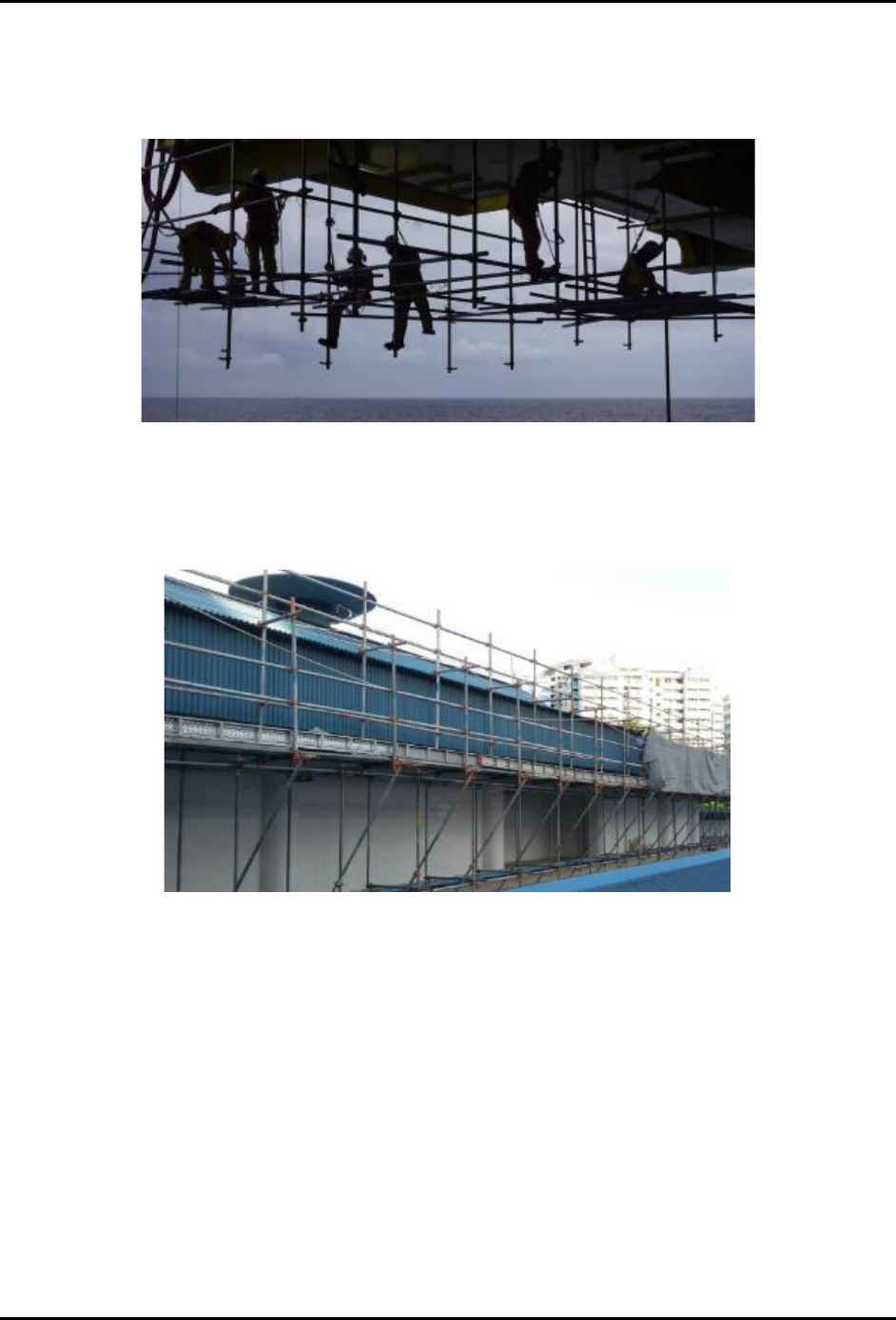
Global EHS - Work At Heights Standard 2W4373RQWREN-1568922467-48
Confidential and Proprietary Information. For Internal Use Only. Revision: 2
Global EHS Controlled Document. Uncontrolled Printed Copy. Date: 19 Jul 2020
© 2020 Micron Technology, Inc. All Rights Reserved. Page 50 of 59
Micron Confidential
6.4.7.5 Hanging Scaffold
A hanging scaffold is a scaffold hung from a structure that is static in the vertical plane; it cannot be raised
or lowered by any means. Hanging scaffolds can be hung from tubes, wire ropes, ropes or chains etc.
Figure 30 Hanging Scaffold
6.4.7.6 Cantilever Scaffold
A cantilever scaffold is a scaffold that is supported by cantilevered load-bearing members.
Figure 31 Cantilever Scaffold
A scaffold in a workplace that is erected on cantilever or jib supports shall be adequately supported, fixed
and anchored on the supports to prevent displacement.
The cantilever or jib supports used to support the scaffold shall —
• have outriggers of adequate length and cross section; and
• be constructed in accordance with the design and drawings of a professional engineer.
The Cantilever scaffold has been inspected by a professional engineer at least once every 3 months to
ensure that it is safe for use.
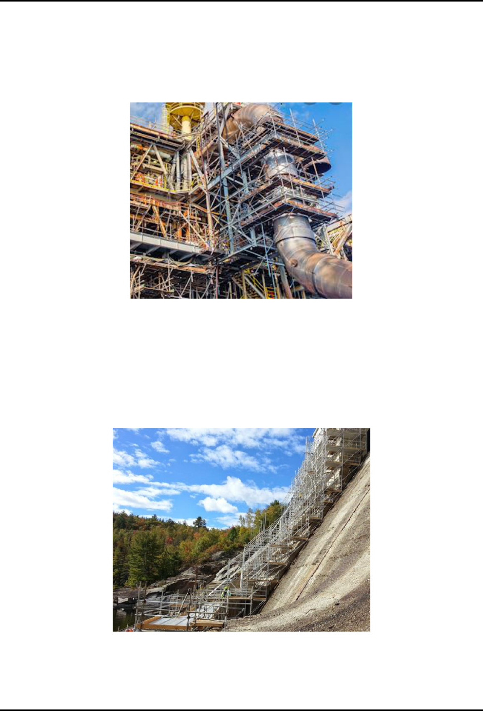
Global EHS - Work At Heights Standard 2W4373RQWREN-1568922467-48
Confidential and Proprietary Information. For Internal Use Only. Revision: 2
Global EHS Controlled Document. Uncontrolled Printed Copy. Date: 19 Jul 2020
© 2020 Micron Technology, Inc. All Rights Reserved. Page 51 of 59
Micron Confidential
6.4.7.7 Tube and Coupler Scaffold
Tube and coupler scaffolds are built from tubing connected by coupling devices. Due to their strength,
they are frequently used where heavy loads need to be carried, or where multiple platforms must reach
several stories high. Their versatility, which enables them to be assembled in multiple directions in a
variety of setting.
Figure 32 Tube and Coupler Scaffold
6.4.7.8 Systems Scaffold
Systems scaffolding consists primarily of vertical and horizontal pre-engineered components that connect
in a systematic fashion. Systems scaffolding is an umbrella term that includes many different types of
scaffolding that can be used to create standardized scaffolding bays
Figure 33 Systems Scaffold

Global EHS - Work At Heights Standard 2W4373RQWREN-1568922467-48
Confidential and Proprietary Information. For Internal Use Only. Revision: 2
Global EHS Controlled Document. Uncontrolled Printed Copy. Date: 19 Jul 2020
© 2020 Micron Technology, Inc. All Rights Reserved. Page 52 of 59
Micron Confidential
6.4.8 Foundation of Scaffolds
Every scaffold in a workplace shall be constructed, erected or installed on structures or foundations of
adequate strength.
6.4.9 Loading requirements for scaffolds
• Site to ensure that signboards stating the maximum permissible weight of tools and materials and the
maximum number of persons permissible on each bay are prominently displayed at suitable locations
on the scaffold in a site.
• The maximum loading for persons and materials allowed on any work platform in any bay of a scaffold
in a workplace shall be 220 kgf per square meter
6.4.10 Designated access point
Every scaffold shall have at least one designated access point from which a person may gain access onto
the scaffold and it shall be clearly marked with a sign or label
6.4.11 Scaffold Tag
A tag, notice, or label shall be clearly displayed at the designated access point indicating that the scaffold
is safe or unsafe for use.
6.4.12 Toe-boards and guard-rails
• Every side of a work platform or workplace from which a person is liable to fall more than 2 meters
shall be provided with toe-boards and 2 or more guard-rails.
• The top guard-rail provided shall be at least 1 meter above the work platform.
• The mid guard-rail approximately halfway between the top rail and the floor. (You can install more
than 1 mid guard-rail if required based on your risk assessment).
• The foot of a standard of any frame or modular scaffold in a workplace shall be secured to a base plate
so that it does not rest directly on the ground or supporting surface.
• Toe-board or netting are required on all work levels of a scaffold to prevent falling objects.
6.4.13 Sole Plate and Base Plate
A scaffold in a workplace exceeding 15 meters in height or being erected on poorly drained soil, base
plates shall bear upon sole plates that are —
• of strength not less than 670 kgf per square meter; or
• of a length suitable to distribute the load.
There shall be no cavity under the sole plate immediately below any standard of a scaffold at the site.

Global EHS - Work At Heights Standard 2W4373RQWREN-1568922467-48
Confidential and Proprietary Information. For Internal Use Only. Revision: 2
Global EHS Controlled Document. Uncontrolled Printed Copy. Date: 19 Jul 2020
© 2020 Micron Technology, Inc. All Rights Reserved. Page 53 of 59
Micron Confidential
Figure 34 Sole Plate and Base Plate
6.4.14 Ties for metal scaffolds
• Every alternate lift and every uppermost lift of an independent tied metal scaffold in a workplace shall
be effectively tied to the building or structure by means of ties.
• Ties shall be located no further than one bay from the ends of the independent tied metal scaffold
and thereafter, at intermediate spacing of not more than 3 bays or 7.5 meters apart, whichever is the
lesser.
• Every tie shall be capable of withstanding a force of 1,000 kgf applied in either direction along the
length of the tie.
6.4.15 Counterweight
• Counterweights shall be made of non-flowable material. Sand, gravel and similar materials that can
be easily dislocated shall not be used as counterweights.
• Only those items specifically designed as counterweights shall be used to counterweight scaffold
systems. Construction materials such as, but not limited to, masonry units and rolls of roofing felt,
shall not be used as counterweights.
• Counterweights shall be secured by mechanical means to the outrigger beams to prevent accidental
displacement.
• Counterweights shall not be removed from an outrigger beam until the scaffold is disassembled.
6.4.16 Inspection and Maintenance Procedure
• All sites to ensure a master scaffold register is in place.
• Procedures should be developed for the inspection and maintenance of the scaffold to ensure it
remains in a safe condition to avoid potential collapse. Attention should also be paid to the condition
of scaffold components, for example corrosion or damage.
• Scaffold shall be inspected:
o Upon completion of its construction, erection or installation;

Global EHS - Work At Heights Standard 2W4373RQWREN-1568922467-48
Confidential and Proprietary Information. For Internal Use Only. Revision: 2
Global EHS Controlled Document. Uncontrolled Printed Copy. Date: 19 Jul 2020
© 2020 Micron Technology, Inc. All Rights Reserved. Page 54 of 59
Micron Confidential
o At intervals of not more than 7 days immediately following the date of the last inspection by the
scaffold supervisor;
o after exposure to weather conditions likely to have affected its strength or stability or to have
displaced any part.
6.4.17 Training Requirements and Competency Assessment
Scaffold erectors and scaffold supervisors shall successfully complete an approved scaffold training in
their specific task that should include familiarization with the local statutory requirements or codes of
practice.
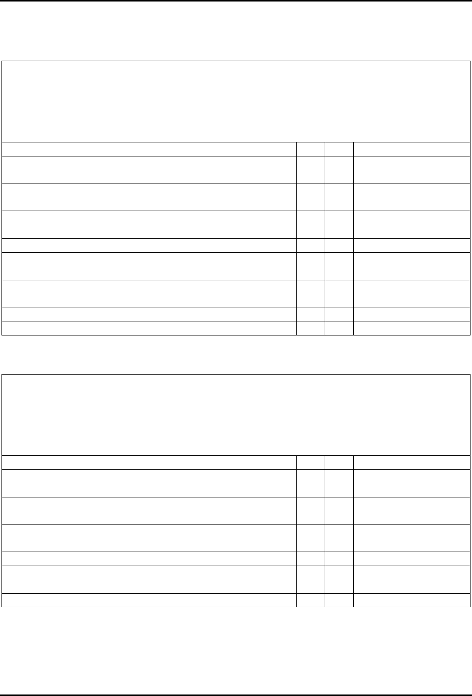
Global EHS - Work At Heights Standard 2W4373RQWREN-1568922467-48
Confidential and Proprietary Information. For Internal Use Only. Revision: 2
Global EHS Controlled Document. Uncontrolled Printed Copy. Date: 19 Jul 2020
© 2020 Micron Technology, Inc. All Rights Reserved. Page 55 of 59
Micron Confidential
7 Appendices
Appendix 1 Constructing Scaffolding Checklist
Constructing Scaffolding Checklist
Date/Time:
Inspected Area:
Inspected By:
Item
Yes
No
Actions/Comments
1. Is the Ground where the scaffold to be erected firm and
not water-logged?
2. Have any excavations near the scaffold which may
endanger its stability or access to it?
3. Have any overhead hazards such as power transmissions
line in the vicinity?
4. Are TM provided with Safety helmets and PPE?
5. Are there a competent scaffolder on site to supervise the
erection?
6. Are the erection location barricaded to prevent non-
relevant TM from entering?
7. Are toes board provided and securely fastened in position?
8. Are guardrail fitted?
Appendix 2 Scaffolding In-Use Checklist
Scaffolding In-Use CHECKLIST
Date/Time:
Inspected Area:
Inspected By:
Item
Yes
No
Actions/Comments
Is the scaffold surrounding and in the vicinity of the bases for
the scaffold not waterlogged?
Are the scaffold components and fitting showing no signs of
deteriorating by rusting?
Are the sole plate and baseplates still in good condition and in
its original position?
Are guardrail fitted in the correct height?
Are the working platform, access way and landings cleared off
any obstruction, loose objects and tripping hazards?
Ensure no unauthorized modification to the scaffold

Global EHS - Work At Heights Standard 2W4373RQWREN-1568922467-48
Confidential and Proprietary Information. For Internal Use Only. Revision: 2
Global EHS Controlled Document. Uncontrolled Printed Copy. Date: 19 Jul 2020
© 2020 Micron Technology, Inc. All Rights Reserved. Page 56 of 59
Micron Confidential
Appendix 3 Dismantling Scaffolding Checklist
Dismantling Scaffolding CHECKLIST
Date/Time:
Inspected Area:
Inspected By:
Item
Yes
No
Actions/Comments
Is the scaffold safe for dismantle?
Has the dismantling sequence been explained to those working
on it prior to starting work each day?
Have barricades been erected to restricted access to the
scaffold?
Have all personnel not involved in the actual dismantling,
removed from the site of the scaffold?
Are the scaffolders wear safety helmets and PPE?
IS there a competent person to supervise the dismantling
operation?

Global EHS - Work At Heights Standard 2W4373RQWREN-1568922467-48
Confidential and Proprietary Information. For Internal Use Only. Revision: 2
Global EHS Controlled Document. Uncontrolled Printed Copy. Date: 19 Jul 2020
© 2020 Micron Technology, Inc. All Rights Reserved. Page 57 of 59
Micron Confidential
8 Document Control
Items
Details
ECN Facility
CORP EHS
ECN Area
EHS SAFETY
Approval
This document is approved by:
GLOBAL_EHS_SEAL_LT
Notification
Notification of changes to this document is managed through Micron’s Engineering
Change Notification (ECN) process to the following:
• GLOBAL_EHS
• GLOBAL_EHS_MANAGERS
• GLOBAL_EHS_SEAL_LT
• GLOBAL_EHS_TEAM_MEMBERS
• GLOBAL_SAFETY_ENGINEERS
• GLOBAL_FAC_NOTIFY
• GLOBAL_FAC_MANAGER
Review
This document will be reviewed at least biennially (once per two years) by Global EHS /
PSM through the Periodic Document Review (PDR) process.

Global EHS - Work At Heights Standard 2W4373RQWREN-1568922467-48
Confidential and Proprietary Information. For Internal Use Only. Revision: 2
Global EHS Controlled Document. Uncontrolled Printed Copy. Date: 19 Jul 2020
© 2020 Micron Technology, Inc. All Rights Reserved. Page 58 of 59
Micron Confidential
9 Revision History
Table 5 Revision History
Rev
Date
Description
Requestor
0
27 Oct
2017
ECN Number: 600961003
First published version
JEREMIAHMOHR
0
08 Nov
2017
ECN Number: Not workflowed
Section 5.3 Admin Update
JEREMIAHMOHR
0
08 Aug
2019
ECN Number: Not workflowed
Periodic Document Review (PDR) completed. No changes required.
DZULEZWAN
1
23 Nov
2019
ECN Number: 101042006
Facilitate and align to Asian standards (6ft=2.0m)
Was:
6.1 Trigger Height
...will be exposed to a fall exceeding six feet (1.8 m). All work at height activities shall be...
6.2 Trigger Height - Exceptions and Clarifications
...to elevated areas in excess of six feet (1.8 m) in height with fall protection provided by...
6.12 Fall Arrest System
...ground or other objects. A standard 6-foot (1.8 m) lanyard anchored at shoulder height will...
Is:
6.1 Trigger Height
...will be exposed to a fall exceeding 6 feet* (2.0 m). All work at height activities shall be...
6.2 Trigger Height - Exceptions and Clarifications
...to elevated areas in excess of 6 feet* (2.0 m) in height with fall protection provided by...
6.12 Fall Arrest System
...ground or other objects. A standard 6-foot* (2.0 m) lanyard anchored at shoulder height will...
* US Only
JEREMIAHMOHR
2
19 Jul
2020
ECN Number: 301064330
Consolidated Ladder and Raised Metal Floor Standards. Added scaffold procedures. Separate ECNs will be
raised for obsoletion of the following documents.
• Global EHS - Work At Heights Ladder Program Standard (2W4373RQWREN-1568922467-47)
• Global EHS - Raised Metal Floor Program Standard (2W4373RQWREN-1568922467-46)
WAS:
1) Title: Global EHS - Work At Heights Program Standard
2) Raised Metal Floor & Ladders standard was in a separate document.
WEIQI

Global EHS - Work At Heights Standard 2W4373RQWREN-1568922467-48
Confidential and Proprietary Information. For Internal Use Only. Revision: 2
Global EHS Controlled Document. Uncontrolled Printed Copy. Date: 19 Jul 2020
© 2020 Micron Technology, Inc. All Rights Reserved. Page 59 of 59
Micron Confidential
3) No Scaffold Procedure Standard
4) 6.1.8 When hole covers are removed, protect the opening with a rigid barricade or guardrail system
IS:
1) Title: Global EHS - Work At Heights Standard
2) Consolidated Raised Metal Floor & Ladders standard
3) Added in Scaffold Standard
4) 6.1.8 When hole covers are removed, protect the opening with a rigid barricade or guardrail system
with a warning signage
5) 6.1.9 (More than 1 mid-rail can be installed if required based on your risk assessment).
6) 6.1.13 body hardness…. or approved by local regulatory body
End of Document
