
Rockwell Automation Publication MOTION-RM003O-EN-P - November 2023
Supercedes Publication MOTION-RM003N-EN-P - November 2022
Original Instructions
Reference Manual
Integrated Motion on the
EtherNet/IP Network
ControlLogix, CompactLogix, Compact GuardLogix,
GuardLogix, Kinetix 350, Kinetix 5300, Kinetix 5500,
Kinetix 5700, Kinetix 6500, PowerFlex 527, PowerFlex 755

Integrated Motion on the EtherNet/IP Network
2 Rockwell Automation Publication MOTION-RM003O-EN-P - November 2023
Important User Information
Read this document and the documents listed in the additional resources section about installation, configuration, and
operation of this equipment before you install, configure, operate, or maintain this product. Users are required to familiarize
themselves with installation and wiring instructions in addition to requirements of all applicable codes, laws, and standards.
Activities including installation, adjustments, putting into service, use, assembly, disassembly, and maintenance are required to
be carried out by suitably trained personnel in accordance with applicable code of practice.
If this equipment is used in a manner not specified by the manufacturer, the protection provided by the equipment may be
impaired.
In no event will Rockwell Automation, Inc. be responsible or liable for indirect or consequential damages resulting from the use
or application of this equipment.
The examples and diagrams in this manual are included solely for illustrative purposes. Because of the many variables and
requirements associated with any particular installation, Rockwell Automation, Inc. cannot assume responsibility or liability for
actual use based on the examples and diagrams.
No patent liability is assumed by Rockwell Automation, Inc. with respect to use of information, circuits, equipment, or software
described in this manual.
Reproduction of the contents of this manual, in whole or in part, without written permission of Rockwell Automation, Inc., is
prohibited.
Throughout this manual, when necessary, we use notes to make you aware of safety considerations.
WARNING:
Identifies information about practices or circumstances that can cause an explosion in a hazardous environment, which may lead to
personal injury or death, property damage, or economic loss.
ATTENTION:
Identifies information about practices or circumstances that can lead to personal injury or death, property damage, or economic loss.
Attentions help you identify a hazard, avoid a hazard, and recognize the consequence.
IMPORTANT
Identifies information that is critical for successful application and understanding of the product.
Labels may also be on or inside the equipment to provide specific precautions.
SHOCK HAZARD: Labels may be on or inside the equipment, for example, a drive or motor, to alert people that dangerous voltage may be present.
BURN HAZARD:
Labels may be on or inside the equipment, for example, a drive or motor, to alert people that surfaces may reach dangerous
temperatures.
ARC FLASH HAZARD:
Labels may be on or inside the equipment, for example, a motor control center, to alert people to potential Arc Flash. Arc Flash will
cause severe injury or death. Wear proper Personal Protective Equipment (PPE). Follow ALL Regulatory requirements for safe work practices and for
Personal Protective Equipment (PPE).
Rockwell Automation recognizes that some of the terms that are currently used in our industry and in this publication are not in
alignment with the movement toward inclusive language in technology. We are proactively collaborating with industry peers to
find alternatives to such terms and making changes to our products and content. Please excuse the use of such terms in our
content while we implement these changes.

Rockwell Automation Publication MOTION-RM003O-EN-P - November 2023 3
Summary of changes
This manual contains new and updated information.
Use these reference tables to locate new or changed information.
Grammatical and editorial style changes are not included in this summary.
Global changes
This table identifies changes that apply to all information about a subject in
the manual and the reason for the change. For example, the addition of new
supported hardware, a software design change, or additional reference
material would result in changes to all of the topics that deal with that subject.
None for this release.
New or enhanced features
This table contains a list of topics changed in this version, the reason for the
change, and a link to the topic that contains the changed information.
Topic Name
Reason
Identify Motion Axis Attributes Based on Device Function
Codes on page 112
Updated Motor Test Flux Saturation, PM Motor Inductance,
Motor Lq Inductance, PM Motor Ld Inductance.
Added Motor Voltage Feedback Source, Motor Voltage
Feedback Offset Mode, Motor Voltage Feedback Threshold,
Motor Voltage Feedback Offset Limit, Slip Compensation
Enable, AC Line Sync Kp, AC Line Sync Ki, AC Line Sync
Configuration, AC Line Resonance Damping Gain, Converter
Disable Delay, Bus Voltage Droop Control Mode, Bus Voltage
Droop Gain Full Load, Bus Voltage Droop Gain No Load, Bus
Voltage Droop Transition Current, Bus Voltage Droop
Minimum Bus Voltage, DBC Mode, DBC Low Voltage
Threshold, DBC High Voltage Threshold, DBC Nominal
Voltage Threshold, DBC Motoring Nominal Power Limit, DBC
Regenerative Nominal Power Limit, DBC Motoring Minimum
Power Limit, DBC Regenerative Minimum Power Limit, AC
Line Voltage Low Pass Filter Bandwidth, Converter Current
Power Feedforward, Converter Inverter Motor Power Limit
Min, Converter Inverter Regen Power Limit Max, and
Converter Input Phase Loss Threshold.
Motion Control Modes on page 18
Added information about Axis Test Mode.
Position Control Mode on page 20 Added information about Axis Test Mode.
Motion Instruction Compatibility on page 25 Added information about Axis Test Mode.
Event Input Sources on page 45 Added information about Axis Test Mode.
Fault and Alarm Behavior on page 47 Added information about Axis Test Mode.
Exceptions on page 48
Added information about Axis Test Mode.
Absolute Position Recovery on page 50
Added information about Axis Test Mode.
Non-regen Converter Axis Behavior on page 67
Added information about Axis Test Mode.
State Behavior on page 74
Added information about Axis Test Mode.

Summary of changes
4 Rockwell Automation Publication MOTION-RM003O-EN-P - November 2023
Topic Name
Reason
Identify attributes from codes on page 112 Added information about Axis Test Mode.
CIP Axis Status Attributes on page 373
Added information about Axis Test Mode.
Drive Commissioning and Tuning Attributes on page 421
Added information about Axis Test Mode.
Hookup Test Result Attributes on page 430
Added information about Axis Test Mode.
Motion Control Config Attributes on page 528
Added information about Axis Test Mode.
Motion Control Interface Attributes on page 537
Added information about Axis Test Mode.
Motion Control Signal Attributes on page 546
Added information about Axis Test Mode.
Motion Control Status Attributes on page 558
Added information about Axis Test Mode.
Axis Safety Status Attributes on page 641 Added information about Axis Test Mode.
Start Inhibits Attributes on page 695
Added information about Axis Test Mode.
Axis Test Mode Attributes on page 729
Added information about Axis Test Mode.
Axis Test Mode Config Attributes on page 729
Added information about Axis Test Mode.
Converter Control Mode Attributes on page 731
Added information about Axis Test Mode.
Module Config Block Attributes on page 773
Added information about Axis Test Mode.
Motion Control Interface Attributes on page 537
Updated Group Instance and Axis Update Schedule.
Motion Control Status Attributes on page 558 Updated Axis Status Bits and the Axis Status Bits table (Axis
Update Status row).
Motion Scaling Attributes on page 598 Updated the Signal Attribute Names for 1402 + o, 1403 + o,
1404 + o, 2380 + o, 2381 + o, 2382 + o, 2383 + o, 2384 + o,
and 2385 + o. Added Slip Compensation Enable.
General Perm Magnet Motor Attributes on page 268 Updated PM Motor Inductance, PM Motor Lq Inductance,
and PM Motor Ld Inductance.
Command Gen Config Attributes on page 268 Updated Ramp Velocity - Positive, Ramp Velocity -
Negative, and Flying Start Method
Torque/Force Control Config Attrib on page 316 Updated Friction Compensation Sliding, Friction
Compensation Static, Friction Compensation Breakaway
Time, Friction Compensation Hysteresis, Friction
Compensation Viscous, Friction Compensation Method,
Adaptive Tuning configuration.
Added Motor Voltage Feedback Source, Motor Voltage
Feedback Offset Mode, Motor Voltage Feedback Threshold,
and Motor Voltage Feedback Offset Limit.
Frequency Control Config Attributes on page 301 Added Slip Compensation Enable
Updated Break Voltage, Break Frequency,Start Boost, Run
Boost, Sensorless Vector Economy Accel Decel Kp,
Sensorless Vector Economy Accel Decel Ki, Sensorless
Vector Economy At Speed Ki, Sensorless Vector Boost Filter
Bandwidth
Stopping and Braking Attributes on page 674
Updated AC Injection Brake Regulator Ki
Converter AC Line Config Attributes on page 719 Added AC Line Sync kp, AC line Sync Ki, AC Line Sync
Configuration, and AC Line Resonance Damping Gain.
Converter Control Mode Attributes on page 731 Updated the Semantics of Values for Converter Startup
Method.
Added Converter Disable Delay.
Rockwell Automation Specific Axis Exceptions on page 766
Added Excessive Motor Voltage Feedback Offset, and AC
Line Phase Reversal.
Rockwell Automation Specific CIP Axis Fault Names on page
770
Added Excessive Motor Voltage Feedback Offset Fault.

Summary of changes
Rockwell Automation Publication MOTION-RM003O-EN-P - November 2023 5
Topic Name
Reason
Rockwell Automation Specific CIP Axis Alarm Names on
page 771
Added Excessive Motor Voltage Feedback Offset Alarm.
Standard Initialization Faults on page 487
Renamed the title from the Exception to Fault.
Rockwell Automation Specific Initialization Faults on page
488
Renamed the title from the Exception to Fault.
Standard Start Inhibits on page 697 Added Invalid Slip Speed, Bus Input Overcurrent Inhibit, and
Invalid Slip Speed Inhibit.
Motor Test Result Attributes on page 440
Added Motor Test Flux Saturation.
AC Line Condition Attributes on page 724
Added Converter Input Phase Loss Threshold.

Rockwell Automation Publication MOTION-RM003O-EN-P - November 2023 7
Table of Contents
Studio 5000 environment ..........................................................................13
Additional Resources ..................................................................................13
Legal Notices .............................................................................................. 15
Chapter 1
Axis Test Mode ............................................................................................17
Integrated Motion Axis Control Modes and Methods ............................ 18
Motion Control Modes......................................................................... 18
Position Control Mode ................................................................. 20
Velocity Control Mode ................................................................... 21
Torque Control Mode ....................................................................23
No Control Mode ...........................................................................23
Motion Control Methods .................................................................... 24
Motion Instruction Compatibility ..................................................... 25
Chapter 2
Acceleration Control Behavior ...................................................................31
Acceleration Limiter ............................................................................ 32
Load Observer ....................................................................................... 33
Command Generation Behavior ............................................................... 34
Command Data Sources ...................................................................... 35
Command Fine Interpolation ............................................................. 36
Command Ramp Generator ................................................................ 39
Feedforward Signal Selection ............................................................ 40
Command Notch Filter ........................................................................ 41
Current Control Behavior .......................................................................... 41
Current Vector Limiter ....................................................................... 42
Voltage Output ..................................................................................... 43
Current Feedback ................................................................................. 43
Motor Commutation ............................................................................ 43
Event Capture Behavior .............................................................................44
Event Input Sources ............................................................................. 45
Event Latches ....................................................................................... 46
Event Time Stamps .............................................................................. 47
Fault and Alarm Behavior .......................................................................... 47
Exceptions ........................................................................................... 48
Absolute Position Recovery ................................................................ 50
Abs Position Loss wo APR Faults ................................................. 52
APR Fault Conditions ................................................................... 52
APR Fault Generation .................................................................... 53
APR Fault Examples ....................................................................... 55
Summary of changes
Preface
Integrated Motion on the
EtherNet/IP Network
Behavior models used in CIP
Motion

Table of Contents
8 Rockwell Automation Publication MOTION-RM003O-EN-P - November 2023
APR Recovery Scenarios ................................................................56
Reset an APR Fault ........................................................................ 60
Motion Control Axis Behavior Model ...................................................... 60
Active Control Axis Behavior Model ................................................... 61
Feedback Only Axis Behavior Model ...................................................65
Non-regen Converter Axis Behavior ................................................... 67
Motor Attributes Model ...................................................................... 69
Position Control Behavior ................................................................... 71
Position Feedback Selection ......................................................... 71
Position PI Gains .......................................................................... 72
Velocity Feedforward .................................................................... 72
Position Loop Output Filters ......................................................... 73
State Behavior ...................................................................................... 74
Torque Control Behavior .................................................................... 85
Torque Input Sources ................................................................... 86
Inertia Compensation .................................................................. 86
Friction Compensation ................................................................ 89
Torque filters .................................................................................. 91
Torque Limiter .............................................................................. 92
Torque to Current Scaling ............................................................. 93
Velocity Control Behavior .................................................................... 93
Closed Loop Velocity Control ........................................................95
Open Loop Frequency Control ..................................................... 98
Chapter 3
Attribute Units ......................................................................................... 106
CIP Data Types ......................................................................................... 107
Device Function Codes ............................................................................ 107
Required vs Optional Axis Attributes ..................................................... 109
Identify attributes from codes ................................................................ 112
Attribute Conversion from SERCOS to Integrated Motion on the
Ethernet/IP Network ............................................................................... 133
Drive Supported Optional Attributes ..................................................... 136
Kinetix 350 Drive Module Optional Attributes ................................ 138
Kinetix 5500 Hardwired STO Drive Module Optional Attributes .. 145
Kinetix 5500 Integrated STO Drive Module Optional Attributes ... 152
Kinetix 5700 Safety Drive Module Optional Attributes .................. 160
Kinetix 5700 Advanced Safety Drive Module Optional Attributes . 168
Kinetix 5700 CIP Safety (EtherNet/IP) Module Optional Attributes
............................................................................................................. 176
Kinetix 5700 CIP Advanced Safety (EtherNet/IP) Module Optional
Attributes ............................................................................................ 186
Interpret the Attribute Tables

Table of Contents
Rockwell Automation Publication MOTION-RM003O-EN-P - November 2023 9
Kinetix 5700 Regenerative Bus Supply Module Optional Attributes
............................................................................................................. 196
Kinetix 6500 Drive Module Optional Attributes ............................. 207
PowerFlex 527 Axis Instance Optional Attributes............................ 213
PowerFlex 755 Standard Drive Module Optional Attributes ........... 219
PowerFlex 755 High Power, Standard Drive Module Optional
Attributes ........................................................................................... 225
PowerFlex 755 Low Power, Non-Network Safety Drive Module
Optional Attributes ............................................................................ 231
PowerFlex 755 High Power, Non-Network Safety Drive Module
Optional Attributes ............................................................................ 237
PowerFlex 755 Low and High Power, STO Only Network Safety
Drive Module Optional Attributes .................................................... 243
PowerFlex 755 Low and High Power, Advanced Safety Network
Safety Drive Module Optional Attributes ........................................ 250
MSG Instruction Access Only Attributes ................................................ 257
Chapter 4
Control Mode Attributes ......................................................................... 264
Acceleration Control Attributes ........................................................ 264
Accel Control Config Attributes ........................................................ 265
Command Ref Generation Attributes ............................................. 268
Command Gen Config Attributes ............................................. 268
Command Generator Signal Attributes .....................................272
Current Control Config Attributes .................................................. 284
Current Control Signal Attributes .................................................... 291
Frequency Control Config Attributes ............................................... 301
Frequency Control Signal Attribute ................................................ 308
Position Loop Signal Attributes ....................................................... 309
Position Loop Config Attributes ....................................................... 312
Torque/Force Control Config Attrib ................................................. 316
Motor Adaptation Attributes ............................................................. 345
Torque/Force Control Signal Attrib .................................................. 349
Velocity Loop Config Attributes ........................................................ 351
Velocity Loop Signal Attributes ......................................................... 358
Data Attributes ......................................................................................... 363
Axis Info Attributes ............................................................................ 363
Frequency Analysis Attributes .......................................................... 366
Data Logging Attributes .................................................................... 368
Axis Statistical Attributes .................................................................. 372
CIP Axis Status Attributes ................................................................. 373
Event Capture Attributes ................................................................... 391
CIP Axis Attributes

Table of Contents
10 Rockwell Automation Publication MOTION-RM003O-EN-P - November 2023
Drive Attributes ........................................................................................ 395
Drive Output Attributes ..................................................................... 395
Drive General Purpose I/O Attributes .............................................. 397
Power - Thermal Mgmnt Config Attrib ........................................... 406
Power - Thermal Mgmnt Status Attrib ............................................ 407
Drive Commissioning and Tuning Attributes ....................................... 421
Auto-Tune Configuration Attributes ................................................ 421
Hookup Test Configuration Attributes ........................................... 429
Hookup Test Result Attributes ......................................................... 430
Inertia Test Config Attributes ........................................................... 433
Inertia Test Result Attributes ............................................................ 436
Motor Test Result Attributes ............................................................ 440
Motor Test Configuration Attributes ............................................... 445
Faults and Alarms Attributes ................................................................... 447
APR Fault Attributes .......................................................................... 447
Axis Exception Action Config Attrib ................................................ 450
Axis Exception Action .................................................................. 454
Configuration Fault Attributes ......................................................... 459
CIP Error Codes ........................................................................... 459
Exception Factory Limit Info Attrib ................................................. 466
Exception User Limit Config Attrib .................................................. 474
Axis Exception, Fault, Alarm Attrib .................................................. 481
Initialization Faults Attributes ........................................................ 486
Standard Initialization Faults ..................................................... 487
Rockwell Automation Specific Initialization Faults ................ 488
Module/Node Fault Alarm Attributes ............................................... 491
Fault Log Attributes ........................................................................... 497
Feedback Attributes ................................................................................ 506
Feedback Interface Types ................................................................. 506
Feedback Configuration Attributes ................................................. 508
General Feedback Info Attributes ..................................................... 524
General Feedback Signal Attributes ................................................. 524
Motion Control Attributes ....................................................................... 527
Motion Control Config Attributes ................................................... 528
Motion Control Interface Attributes ................................................ 537
Motion Control Signal Attributes ..................................................... 546
Motion Control Status Attributes ..................................................... 558
Motion Database Storage Attributes ................................................ 569
Motion Dynamic Config Attributes .................................................. 575
Motion Homing Config Attributes ................................................... 578
Motion Planner Config Attributes ................................................... 590
Motion Planner Output Attributes ................................................... 597

Table of Contents
Rockwell Automation Publication MOTION-RM003O-EN-P - November 2023 11
Motion Scaling Attributes .................................................................598
Motion Resolution Value Examples ........................................... 611
Motor Attributes ....................................................................................... 613
General Linear Motor Attributes ...................................................... 613
General Motor Attributes .................................................................. 615
General Perm Magnet Motor Attributes ......................................... 622
General Rotary Motor Attributes ...................................................... 625
Induction Motor Attributes .............................................................. 628
Linear PM Motor Attributes ............................................................. 630
Interior Perm Magnet Motor Attrib ................................................. 633
Load Transmission-Actuator Attrib .................................................. 636
Rotary PM Motor Attributes .............................................................. 638
Safety Attributes ....................................................................................... 641
Axis Safety Status Attributes ............................................................. 641
Guard Safety Attributes ..................................................................... 659
Guard Safety Status Attributes ........................................................ 660
Drive Safety Attributes ...................................................................... 667
Stopping and Braking Attributes ............................................................ 674
Stopping Sequences .......................................................................... 690
Proving Operational Sequences ........................................................ 693
Start Inhibits Attributes .................................................................... 695
Standard Start Inhibits ............................................................... 697
Rockwell Automation Specific Start Inhibits ........................... 698
DC Bus Condition Attributes ................................................................. 700
Converter AC Line Input Attributes ........................................................ 712
Converter AC Line Monitor Attributes ............................................. 712
Converter AC Line Config Attributes ............................................... 719
Convert AC Line Source Config Attrib .............................................722
AC Line Condition Attributes ............................................................ 724
Structural Vibration Attributes ......................................................... 727
Axis Test Mode Attributes ........................................................................ 729
Axis Test Mode Config Attributes ..................................................... 729
Converter Control Attributes ..................................................................730
Converter Types .................................................................................730
Converter Control Mode Attributes.................................................. 731
Convert BusVolt ControlConfig Attrib ............................................. 735
ConvertBus VoltControl Signal Attrib ............................................. 740
Converter Current Ref Config Attrib................................................ 743
Converter Current Ref Signal Attrib ................................................ 745
ConvertCurrent Control Config Attrib............................................. 746
ConvertCurrent Control Signal Attrib ............................................. 748
Converter ReactivePowerControlAttrib ........................................... 755

Table of Contents
12 Rockwell Automation Publication MOTION-RM003O-EN-P - November 2023
Converter Output Attributes ............................................................. 756
Exceptions ................................................................................................. 757
Standard Axis Exceptions .................................................................. 757
Stndrd CIP Axis Fault - Alarm Names ........................................... 762
Rockwell Automation Specific Axis Exceptions .............................. 766
Rockwell Automation Specific CIP Axis Fault Names .....................770
Rockwell Automation Specific CIP Axis Alarm Names ................... 771
Chapter 5
Module Config Block Attributes ............................................................. 773
Module Class Attributes .......................................................................... 775
Module Axis Attributes ............................................................................ 777
Module Feedback Port Attributes ........................................................... 796
Module Timing Attributes ....................................................................... 797
Module Support Parameters .................................................................. 800
Module Configuration Attributes
Index

Rockwell Automation Publication MOTION-RM003O-EN-P - November 2023 13
Preface
Use this manual to review descriptions of the AXIS_CIP_DRIVE attributes
and the Studio 5000 Logix Designer® application Control Modes and
Methods.
It is intended for use as a reference when programming motion applications.
The Studio 5000 Automation Engineering & Design Environment® combines
engineering and design elements into a common environment. The first
element is the Studio 5000 Logix Designer® application. The Logix Designer
application is the rebranding of RSLogix 5000® software and will continue to
be the product to program Logix 5000™ controllers for discrete, process,
batch, motion, safety, and drive-based solutions.
The Studio 5000® environment is the foundation for the future of
Rockwell Automation® engineering design tools and capabilities. The Studio
5000 environment is the one place for design engineers to develop all
elements of their control system.
Use the following resources to get additional information concerning related
products and technologies:
Publication Title
Description
CompactLogix™ 5370 Controllers User Manual,
publication 1769-UM021
Describes the necessary tasks to install, configure,
program, and operate a CompactLogix 5370 controller.
ControlLogix® System User Manual, publication
1756-UM001
Describes the necessary tasks to install, configure,
program, and operate a ControlLogix system.
EtherNet/IP Network Configuration User Manual,
publication ENET-UM001
Describes Ethernet network considerations, networks,
and setting IP addresses.
Integrated Architecture® and CIP Sync Configuration
Application Technique, publication IA-AT003
Provides detailed configuration information on CIP
Sync Technology and time synchronization.
Integrated Motion on the EtherNet/IP Network
Configuration and Startup User Manual, publication
MOTION-UM003
Describes how to configure an integrated motion
application and to start up your motion solution by
using the ControlLogix system.
Studio 5000 environment
Additional Resources

Preface
14 Rockwell Automation Publication MOTION-RM003O-EN-P - November 2023
Publication Title
Description
Kinetix® 6200 and Kinetix 6500 Modular Mutli-axis
Servo Drives User Manual, publication 2094-UM002
Provides information on how to install, configure, and
troubleshoot applications for your Kinetix 6200 and
Kinetix 6500 servo drive systems.
Kinetix 6200 and Kinetix 6500 Safe Speed Monitoring
Safety Reference Manual, publication 2094-RM001
Provides information on wiring, configuring, and
troubleshooting the safe-speed features of your
Kinetix 6200 and Kinetix 6500 drives.
Kinetix 6200 and Kinetix 6500 Safe Torque Off Safety
Reference Manual, publication 2094-RM002
Provides information on wiring, configuring, and
troubleshooting the safe torque-off features of your
Kinetix 6200 and Kinetix 6500 drives.
Kinetix 5500 Servo Drives User Manual, publication
2198-UM001
Provides information on install, configure, and
troubleshoot applications for your Kinetix 5500 drive.
Kinetix 5700 Servo Drives User Manual, publication
2198-UM002
Provides information on install, configure, and
troubleshoot applications for your Kinetix 5700 drive.
Kinetix 350 Single-axis EtherNet/IP Servo Drives User
Manual, publication 2097-UM002
Provides information on install, configure, and
troubleshoot applications for your Kinetix 350
Single-axis EtherNet/IP Servo drive.
Kinetix Safe-off Feature Safety Reference Manual,
publication GMC-RM002
Provides information on wiring and troubleshooting
your Kinetix 6000 and Kinetix 7000 servo drives with
the safe torque-off feature.
Logix5000™ Motion Controllers Motion Instructions
Manual, publication MOTION-RM002
Provides a programmer with details about motion
instructions for motion control.
Logix5000 Controllers Common Procedures,
publication 1756-PM001
Provides detailed and comprehensive information
about how to program a Logix5000 controller.
Logix5000 Controllers General Instructions Reference
Manual, publication 1756-RM003
Provides a programmer with details about general
instructions for a Logix-based controller.
Logix5000 Controllers Advanced Process Control and
Drives Instructions Reference Manual, publication
1756-RM006
Provides a programmer with details about process and
drives instructions for a Logix-based controller.
Motion Coordinate System User Manual, publication
MOTION-UM002
Provides details on how to create and configure a
coordinate motion system.
PowerFlex® 527 Adjustable Frequency AC Drive User
Manual, publication 520-UM002
Provides information that is needed to install, start-up,
and troubleshoot PowerFlex 527-Series Adjustable
Frequency AC drives.
PowerFlex 750-Series AC Drives Programming Manual,
publication 750-PM001
Provides information that is needed to install, start-up,
and troubleshoot PowerFlex 750-Series Adjustable
Frequency AC drives.
PowerFlex 755 Drive Embedded EtherNet/IP Adapter
User Manual, publication 750COM-UM001
Provides information on how to install, configure, and
troubleshoot applications for the PowerFlex 755 Drive
Embedded EtherNet/IP adapter.
Industrial Automation Wiring and Grounding
Guidelines, publication 1770-4.1
Provides general guidelines for installing a Rockwell
Automation® industrial system.
Rockwell Automation® Product Certifications Provides declarations of conformity, certificates, and
other certification details.
ODVA™ specifications ODVA, is the organization that supports network
technologies that are built on the Common Industrial
Protocol (CIP) — DeviceNet, EtherNet/IP, CompoNet,
and ControlNet.
You can view or download publications at
http://www.rockwellautomation.com/literature. To order paper copies of
technical documentation, contact your local Rockwell Automation distributor
or sales representative.

Preface
Rockwell Automation Publication MOTION-RM003O-EN-P - November 2023 15
Rockwell Automation publishes legal notices, such as privacy policies, license
agreements, trademark disclosures, and other terms and conditions on the
Legal Notices page of the Rockwell Automation website.
Software and Cloud Services Agreement
Review and accept the Rockwell Automation Software and Cloud Services
Agreement here.
Open Source Licenses
The software included in this product contains copyrighted software that is
licensed under one or more open source licenses. Copies of those licenses are
included with the software. Corresponding Source code for open source
packages included in this product are located at their respective web site(s).
Alternately, obtain complete Corresponding Source code by contacting
Rockwell Automation via the Contact form on the Rockwell Automation
website:
http://www.rockwellautomation.com/global/about-us/contact/contact.page
Please include "Open Source" as part of the request text.
A full list of all open source software used in this product and their
corresponding licenses can be found in the OPENSOURCE folder. The default
installed location of these licenses is
C:\Program Files (x86)\Common
Files\Rockwell\Help\<Product Name>\Release
Notes\OPENSOURCE\index.htm
.
Legal Notices

Rockwell Automation Publication MOTION-RM003O-EN-P - November 2023 17
Chapter 1
Integrated Motion on the EtherNet/IP Network
Use this manual to review reference descriptions of the AXIS_CIP_DRIVE
attributes, Axis Test Mode attributes, and the Studio 5000 Logix Designer®
application Control Modes and Methods.
Review Axis Test Mode on page 17.
Review Motion Control Modes on page 18 for a reference for the Motion
Control Modes and Motion Control Methods that explains when you can use
an axis attribute in an individual control mode.
To learn about how the different control modes function with attributes
review the diagrams provided in Behavior models used in CIP Motion on page
31.
The Control Modes table lists the Motion Axis Attributes specific to the CIP
Drive data type. The table identifies the attribute implementation rule as
either Required, Optional, or Conditional. Drive replicated attributes are
identified also.
Review the Interpret the Attribute Tables on page 103 section for an
explanation of how the data for the attributes are organized.
CIP Axis Attributes cover a wide range of drive types. The CIP Axis Attributes
on page 261 topics contain:
• Detailed attribute definitions
• Configurations
• Status
• Faults
Each attribute is in a table that includes information about:
• Usage
• Access
• Data type
• Default, minimum, and maximum values
• Semantics of values
Attributes associated with components that are common to all axis instances
of a multi-axis CIP Motion device or module are detailed in Module
Configuration Attributes on page 773.
Use Axis Test Mode to develop and test application programs without a
controller-network connection to a set of physical CIP Motion drives, motors,
Axis Test Mode

Chapter 1 Integrated Motion on the EtherNet/IP Network
18 Rockwell Automation Publication MOTION-RM003O-EN-P - November 2023
or machine components.
Perform development and testing without modifying the application
program’s motion instructions or motion-safety instructions that are
configured to execute on CIP axes. By enabling the Axis Test Mode and setting
the Axis Test Mode configuration, the same logic works on real hardware.
See Motion Control Modes on page 18, Behavior models used in CIP Motion
on page 31, Interpret the Attribute Tables on page 103, and CIP Axis Attributes
on page 261 for more information regarding limitations and nuances.
The Motion Control Axis Object covers the behavior of various motion control
system devices that includes feedback devices, drive devices, standalone
regenerative and non-regenerative converters, and motion I/O devices. For
drive devices, the Motion Control Axis Object covers a wide range of drive
types from simple variable frequency (V/Hz) drives, to sophisticated position
control servo drives, with or without integral converters. Many commercial
drive products have axes that can be configured with instructions to operate
in any one of these different motion control modes depending on the specific
application requirements.
Based on the variations in Motion Control Mode and Motion Control Method,
a set of basic Device Function Codes have been defined that help organize the
many attributes of the Motion Control Axis. Each attribute has a unique
identifier (ID).
See also
Motion Control Modes on page 18
Motion Control Methods on page 24
Motion Instruction Compatibility on page 25
Device Function Codes on page 107
Identify Motion Axis Attributes Based on Device Function Codes on
page 112
Motion control modes are organized around the general philosophy that
position control is the highest form of dynamic control. That is, position
control implies velocity control, and velocity control implies acceleration
control.
Acceleration is related to torque or force by the inertia or mass of the load;
respectively, acceleration control implies torque control. Because motor
torque or force is related to motor current by a torque or force constant,
respectively, torque control implies current control. The torque or force
Integrated Motion Axis
Control Modes and Methods
Motion Control Modes

Chapter 1 Integrated Motion on the EtherNet/IP Network
Rockwell Automation Publication MOTION-RM003O-EN-P - November 2023 19
constant can be a function of the motor magnets as in a Permanent Magnet
motor, or the induced flux of an Induction motor.
Because acceleration, torque/force, and current are related by a constant,
these terms are sometimes used interchangeably in the industry. For example,
a torque control loop rather than a current control loop. Motion Control Axis
Attributes let you differentiate between these control properties. This
attribute is useful when the relationship between them is not static, such as
when inertia/mass changes with position or time, or when the torque/force
constant changes due to temperature change or motor flux variation.
Control Modes
Control Mode
Axis Test Mode Support
(Test Mode Configuration)
B - Bus Power Converters (No Control Mode, No
Control Method)
Controller Loop Back: V35
(Enables Inverter Axes in an associated Bus Sharing Group
to transition to Running Sate. Simulates axis-state
transitions and status.)
E - Encoder, Feedback Only (No Control Mode, No
Control Method)
Controller Loop Back: V35
(Simulates axis-state transitions and status.)
P - Position Control Mode Controller Loop Back: V35
(Simulation tracks the Actual Position to the Command
Position with a simulated controller-drive interface delay.)
(Simulates axis-state transitions and status.)
Controller Loop Back: V36
(Simulation supports Motion Safety Instructions.)
V - Velocity Control Mode Controller Loop Back: V35
(Motion is not simulated in this Control Mode so actual
values do not change in response to changes in command
values.)
(Simulates axis-state transitions and status.)
T - Torque Control Mode Controller Loop Back: V35
(Motion is not simulated in this Control Mode so actual
values do not change in response to changes in command
values.)
(Simulates axis-state transitions and status.)
F - Velocity Control Mode Controller Loop Back: V35
(Motion is not simulated in this Control Mode so actual
values do not change in response to changes in command
values.)
(Simulates axis-state transitions and status.)

Chapter 1 Integrated Motion on the EtherNet/IP Network
20 Rockwell Automation Publication MOTION-RM003O-EN-P - November 2023
Motion Control Nomenclature
Linear and rotary control applications can affect the control nomenclature.
While rotary applications speak of torque and inertia, linear applications
speak of force and mass. When we refer to rotary nomenclature, the defined
behavior can generally be applied to linear applications by substituting the
terms, force for torque and mass for inertia. With that understanding, we use
torque rather than force in the control mode diagrams without loss of
generality.
See also
Position Control Mode on page 20
Velocity Control Mode on page 21
Torque Control Mode on page 23
No Control Mode on page 23
In Position Control application mode, either the application control program
(command execution function) or the motion planner (move trajectory
control function) provide a setpoint value to the CIP Motion device using the
cyclic data connection. The Position Control method can be either open loop
or closed loop.
Open Loop Position Control Method
A device configured for open loop position control applies to a class of drive
devices called stepper drives.
A feedback device for this configuration is optional. In the absence of a
feedback device, the drive estimates the actual position and returns it to the
controller.
Closed Loop Position Control Method
A motor control device configured for closed loop position control is
traditionally referred to as position loop drive or position servo drive. A
position servo drive implies an inner velocity and torque control loop as
Position Control Mode

Chapter 1 Integrated Motion on the EtherNet/IP Network
Rockwell Automation Publication MOTION-RM003O-EN-P - November 2023 21
shown in the diagram. The presence of the torque/current control loop
sometimes results in this kind of drive being referred to as a vector drive.
A feedback device for this configuration is required to achieve good
positioning accuracy. The feedback device can also be used to return Actual
Velocity and Actual Acceleration data to the controller using the cyclic data
connection.
In addition to Command Position, the controller can pass Command Velocity
and Command Acceleration for the purposes of forward control.
Physical Controller Connected to Drive Physical Controller with Axis Test Mode
(Test Mode Configuration: Controller Loop Back: V35)
Axis Test Mode
Axes with the Test Mode Enable attribute set to Enabled and that are
configured for Controller Loop Back simulate the drive in Position Loop
control mode.
See also
Motion Control Modes on page 18
In Velocity Control application mode, the application control program and
motion planner provide a setpoint value to the CIP Motion device using the
cyclic data connection. The velocity control method can be either open loop or
closed loop.
Open Loop Velocity Control Method
A motor control device configured for open loop velocity control is
traditionally referred to as Variable Frequency, or V/Hz, or VFD, drive.
Velocity Control Mode

Chapter 1 Integrated Motion on the EtherNet/IP Network
22 Rockwell Automation Publication MOTION-RM003O-EN-P - November 2023
A feedback device for this configuration is optional. In the absence of a
feedback device, the drive estimates the actual velocity and returns it to the
controller.
Closed Loop Velocity Control Method
A motor control device configured for closed loop velocity control is
traditionally referred to as velocity loop drive or velocity servo drive. A closed
loop velocity control drive implies an inner torque/current control loop and
therefore is sometimes referred to as a vector drive.
A feedback device for the velocity loop drive configuration is optional. You can
achieve tighter speed regulation when using a feedback device, particularly at
low speed. When the feedback device is included, it may be used to return
actual position, velocity, and acceleration data to the controller using the
cyclic data connection. When the feedback device is not included, only the
estimated velocity can typically be returned to the controller.
In addition to Command Velocity, the controller can also pass Command
Acceleration for the purposes of forward control.
Acceleration Control Method
While not a mainstream control mode in the industry nor mentioned in the
IEC standard, the acceleration control mode is included here to complete the
dynamic progression from velocity control to torque control and because the
Motion Control Axis Object can support an Acceleration Command,
potentially derived from the controller's motion planner. In the acceleration
control mode, the application control program and motion planner provide
acceleration setpoint values to the CIP Motion device using the cyclic data
connection. The drive converts the acceleration set-point into a torque
command using the estimated system inertia. Acceleration control works in
concert with the inner torque/current control loop as shown in the diagram.

Chapter 1 Integrated Motion on the EtherNet/IP Network
Rockwell Automation Publication MOTION-RM003O-EN-P - November 2023 23
A feedback device for the acceleration control configuration is mandatory and
may be used to return actual position, velocity, and acceleration data to the
controller using the cyclic data connection.
See also
Motion Control Modes on page 18
In Torque Control application mode, the application control program or the
motion planner provide torque setpoint values to the device using the cyclic
data connection. Because motor current and motor torque are related by a
torque constant, Kt, torque control is often synonymous with current control.
A position feedback device for this control mode is optional. If a feedback
device is present, it can be used to return actual position, velocity, and
acceleration data to the controller using the cyclic data connection.
See also
Motion Control Modes on page 18
The Motion Control Axis Object supports a No Control application mode
where there is no dynamic motor control function. This mode is often used to
support Feedback Only or Master Feedback functionality where a feedback
channel in a CIP Motion Drive device is serving as a master feedback source to
the rest of the control system. This mode could also be applied to integrated
CIP Motion Encoder device types where the CIP Motion interface is applied
directly to an Encoder.
Torque Control Mode
No Control Mode

Chapter 1 Integrated Motion on the EtherNet/IP Network
24 Rockwell Automation Publication MOTION-RM003O-EN-P - November 2023
In this No Control mode of operation, no command value is supplied to the
CIP Motion device using the cyclic data connection, but actual position,
velocity, and acceleration can be produced by the device to the controller
using the cyclic data channel, if applicable. The No Control mode for Feedback
Only functionality is illustrated in this diagram:
No Control (Feedback Only)
No Control mode also applies to other CIP Motion device types, such as
standalone Bus Power Converters and dedicated Motion I/O device types.
Since there is no feedback channel that is associated with these device types,
no actual position is returned to the controller.
See also
Motion Control Modes on page 18
Within this basic motion control paradigm, there is latitude for different
control methods, both closed loop and open loop. By closed loop, it is implied
that there is a feedback signal that is used to drive the actual dynamics of the
motor to match the commanded dynamics by the servo action.
In most cases, there is a literal feedback device to provide this signal, and in
some cases the signal is derived from the motor excitation, for example,
sensorless/encoderless operation.
By open loop, it is implied that there is no application of feedback to force the
actual dynamics to match the commanded dynamics. While precision and
performance are the hallmarks of closed loop control, simplicity and economy
are the hallmarks of open loop control.
The Control Method attribute is an 8-bit enumerated code that determines the
basic control algorithm. The device applies the algorithm to control the
dynamic behavior of the motor that is associated with an axis. The Control
Methods related to the Control Modes are listed in the following table.
Control Method Filed Enumeration Definitions
Enumeration
Usage
Name
Description
Motion Control Methods

Chapter 1 Integrated Motion on the EtherNet/IP Network
Rockwell Automation Publication MOTION-RM003O-EN-P - November 2023 25
Enumeration
Usage
Name
Description
0 R/N No Control No Control is associated with a Control Mode of No
Control where there is no explicit motor control that
is provided by the device for this axis instance.
1 R/F Frequency Control Frequency Control is an "open loop" control method
that applies voltage to the motor, generally in
proportion to the commanded frequency or speed.
This control method is associated with Variable
Frequency Drives (VFDs) or so called Volts/Hertz
drives.
2 R/C PI Vector Control PI Vector Control is a "closed loop" control method
that uses actual or estimated feedback for closed
loop cascaded PI control of motor dynamics, that is,
position, velocity, acceleration, and torque, and
always includes independent closed loop PI control
of Iq and Id components of the motor current
vector.
3...127 - Reserved -
128...255 - Vendor Specific -
Axis configuration
The Control Mode and Control Method are derived by the Axis Configuration
according to the following table.
Axis Configuration
Valid Control Modes
Non-Regenerative AC/DC Converter
No Control
Regenerative AC/DC Converter
No Control
Low Harmonic AC/DC Converter
No Control
DC/DC Converter No Control
Feedback Only No Control
Frequency Control Velocity Control
Position Loop Position Control
Velocity Control
Torque Control
Velocity Loop
Velocity Control
Torque Control
Torque Loop Torque Control
Itrack Section
No Control
See also
Motion Control Modes on page 18
The following table correlates the motion instructions with the compatible
control modes. The compatibility with integrated motion is based on the Axis
Configuration and feedback type settings. The motion instructions tables are
divided by type.
Motion Instruction
Compatibility

Chapter 1 Integrated Motion on the EtherNet/IP Network
26 Rockwell Automation Publication MOTION-RM003O-EN-P - November 2023
Use the following key to interpret the column entries:
Symbol
Meaning
x
Control mode is compatible.
#
MSO and MDS execution initiate mutually exclusive modes of operation and execution is
conditional on mode.
*
Axis may be used as a master axis reference only for this instruction.
c
Axis may conditionally use Motion Planner instructions if enabled with an MSO instruction;
otherwise, there is an error.
S
Supported in Controller Loop Back Configuration of Axis Test Mode.
Instruction provides an ideal response, executes successfully, and sequences as expected.
Support includes some error conditions. Corner-case scenarios that might not be possible for
axis with Axis Test Mode enabled setting must be modified to allow successful sequencing of the
program.
N
Not Supported in Controller Loop Back Configuration of Axis Test Mode.
Instructions that have specific error codes or do not complete.
Instructions that do not generate errors, complete, but do not perform the instruction function.
Instruction logic in the user program for axis with Axis Test Mode enabled setting must be
modified as Axis to allow sequencing of the program.
Shaded areas denote that Multi-Axis Coordination Motion is designed and tested for position
mode operation but not restricted to that axis configuration.
Category
Motion Instruction Name
Abbr.
Feedback Only
Freq.Cntrl
No Feedback
Pos.
Loop
Vel. Loop
Feedback
Vel. Loop
No Feedback
Torque
Loop
Axis Test
Mode
Support
(Test
Mode
Configurat
ion)
State Control
Motion Direct Drive On MDO
Motion Direct Drive Off
MDF
Motion Servo On MSO #S xS #S #S #S Controller
Loop Back:
V35
Motion Servo Off MSF xS xS xS xS xS Controller
Loop Back:
V35
Motion Axis Fault Reset MAFR xS xS xS xS xS xS Controller
Loop Back:
V36
Motion Axis Shutdown MASD xS xS xS xS xS xS Controller
Loop Back:
V35
Motion Axis Shutdown Reset MASR xS xS xS xS xS xS Controller
Loop Back:
V35
Motion Drive Start MDS # # # #

Chapter 1 Integrated Motion on the EtherNet/IP Network
Rockwell Automation Publication MOTION-RM003O-EN-P - November 2023 27
Category Motion Instruction Name Abbr. Feedback Only Freq.Cntrl
No Feedback
Pos.
Loop
Vel. Loop
Feedback
Vel. Loop
No Feedback
Torque
Loop
Axis Test
Mode
Support
(Test
Mode
Configurat
ion)
Event Control
Motion Arm Watch Position MAW xN xS xN xN Controller
Loop Back:
V35
Motion Disarm Watch
Position
MDW xN xS xN xN Controller
Loop Back:
V35
Motion Arm Registration MAR xN xN xN xN N-Controlle
r Loop
Back: V35
(Instruction
does not
complete
because
Events are
not
supported.)
Motion Disarm Registration MDR xN xN xN xN N-Controlle
r Loop
Back: V35
(Instruction
does not
complete
because
Events are
not
supported.)
Motion Arm Output Cam MAOC xN xS xN xN Controller
Loop Back:
V35
Motion Disarm Output Cam MDOC xN xS xN xN Controller
Loop Back:
V35
Move Control
Motion Redefine Position MRP xS cS xS cS cS cS Controller
Loop Back:
V35
Motion Axis Home MAH xS xS cS cS Controller
Loop Back:
V35
(Instruction
only
supports
Immediate
homing.)
Motion Axis Jog MAJ cN xS cN cN Controller
Loop Back:
V35

Chapter 1 Integrated Motion on the EtherNet/IP Network
28 Rockwell Automation Publication MOTION-RM003O-EN-P - November 2023
Category Motion Instruction Name Abbr. Feedback Only Freq.Cntrl
No Feedback
Pos.
Loop
Vel. Loop
Feedback
Vel. Loop
No Feedback
Torque
Loop
Axis Test
Mode
Support
(Test
Mode
Configurat
ion)
Motion Axis Move MAM cN xS cN cN Controller
Loop Back:
V35
Motion Change Dynamics MCD cN xS cN cN Controller
Loop Back:
V35
Motion Axis Stop MAS xS xS xS xS xS xS Controller
Loop Back:
V35
Motion Axis Gear MAG *N cN xS cN cN *N Controller
Loop Back:
V35
Motion Master Driven Axis
Control
MDAC *N cN xS cN cN *N Controller
Loop Back:
V35
Motion Axis Position Cam MAPC N N xS cN cN *N Controller
Loop Back:
V35
Motion Axis Time Cam MATC cN xS cN cN Controller
Loop Back:
V35
Multi-Axis
Coordinate
Motion Coordinated Linear
Move
MCLM cN xS cN cN Controller
Loop Back:
V35
Motion Coordinated Circular
Move
MCCM cN S cN cN Controller
Loop Back:
V35
Motion Coordinated Stop MCS xS xS xS xS xS xS Controller
Loop Back:
V35
Motion Coordinated
Shutdown
MCSD xS xS xS xS xS xS Controller
Loop Back:
V35
Motion Coordinated
Shutdown Reset
MCSR x xS xS xS xS xS Controller
Loop Back:
V35
Motion Coordinated Change
Dynamics
MCCD xN xS xN xN Controller
Loop Back:
V35
Motion Coordinated
Transform
MCT xN xS xN xN Controller
Loop Back:
V35
Motion Calculate Target
Position
MCTP xS xS xS xS xS xS Controller
Loop Back:
V35

Chapter 1 Integrated Motion on the EtherNet/IP Network
Rockwell Automation Publication MOTION-RM003O-EN-P - November 2023 29
Category Motion Instruction Name Abbr. Feedback Only Freq.Cntrl
No Feedback
Pos.
Loop
Vel. Loop
Feedback
Vel. Loop
No Feedback
Torque
Loop
Axis Test
Mode
Support
(Test
Mode
Configurat
ion)
Motion Master Driven
Coordinated Control
MDCC *N xN xS xN *N *N Controller
Loop Back:
V35
Motion
Configuration
Motion Run Axis Tuning MRAT xN xN xN Controller
Loop Back:
V35
(Instruction
returns
error as
Loopback
model
doees not
support
Tuning.)
Motion Apply Axis Tuning MAAT xN Controller
Loop Back:
V35
(Instruction
returns
error as
Loopback
model
doees not
support
Tuning.)
Motion Run Hookup
Diagnostic
MRHD xN xN xN xN xN xN Controller
Loop Back:
V35
(Instruction
returns
error as
Loop Back
model does
not
support
Diagnostic
tests.)

Chapter 1 Integrated Motion on the EtherNet/IP Network
30 Rockwell Automation Publication MOTION-RM003O-EN-P - November 2023
Category Motion Instruction Name Abbr. Feedback Only Freq.Cntrl
No Feedback
Pos.
Loop
Vel. Loop
Feedback
Vel. Loop
No Feedback
Torque
Loop
Axis Test
Mode
Support
(Test
Mode
Configurat
ion)
Motion Apply Hookup
Diagnostic
MAHD xN Controller
Loop Back:
V35
(Instruction
returns
error as
Loop Back
model does
not
support
Diagnostic
tests.)
Group Control
Motion Group Strobe Position MGSP xN xN xS xN xN xN Controller
Loop Back:
V35
Motion Group Shutdown MGSD xS xS xS xS xS xS Controller
Loop Back:
V35
Motion Group Shutdown
Reset
MGSR xS xS x xS xS xS Controller
Loop Back:
V35
Motion Group Stop MGS xS xS x xS xS xS Controller
Loop Back:
V35

Rockwell Automation Publication MOTION-RM003O-EN-P - November 2023 31
Chapter 2
Behavior models used in CIP Motion
Control systems and algorithms are used to discuss the CIP motion attributes.
Conceptual diagrams and feature descriptions are provided to help orient you
to the various components of CIP motion.
Behavior models
Acceleration Control Behavior on page 31 Motor Attributes Model on page 69
Command Generation Behavior on page 34 Position Control Behavior on page 71
Current Control Behavior on page 41 State Behavior on page 74
Event Capture Behavior on page 44
Torque Control Behavior on page 85
Fault and Alarm Behavior on page 47
Velocity Control Behavior on page 93
Motion Control Axis Behavior Model on page 60
See also
Standard Exceptions on page 757
Interpret the Attribute Tables on page 103
While dynamic motor control through an acceleration command is not
common in the industry, Acceleration Control completes the dynamic
progression from Velocity Control to Torque Control. The output of the
velocity loop, Velocity Loop Output, also has units of acceleration. The sum
the contributions of the Acceleration Command, Acceleration Trim, and
Velocity Loop Output to form the Acceleration Reference signal that serves as
one of the primary inputs to Torque Control behavior. Acceleration Control
can optionally include a Load Observer to compensate for mechanical
backlash, mechanical compliance, and various load disturbances.
The following diagram provides an overview of the Acceleration Control
behavior model, including the Load Observer.
Acceleration Control
Behavior

Chapter 2 Behavior models used in CIP Motion
32 Rockwell Automation Publication MOTION-RM003O-EN-P - November 2023
See also
Acceleration Limiter on page 32
Load Observer on page 33
The output of the acceleration command summing junction signal passes
through a limiter to produce the Acceleration Reference signal. The Accel
Limiter applies a directional acceleration limit, either the Acceleration Limit
or the Deceleration Limit, to the input command signal based on the sign of
the signal.
The following diagram illustrates this process.
See also
Load Observer on page 33
Acceleration Control Behavior on page 31
Acceleration Limiter

Chapter 2 Behavior models used in CIP Motion
Rockwell Automation Publication MOTION-RM003O-EN-P - November 2023 33
Acceleration Control can optionally include a Load Observer. Feeding the
Acceleration Reference into a Load Observer, along with the velocity feedback
signal, has been found to be effective in compensating for mechanical
backlash, mechanical compliance, and various load disturbances.
The Load Observer's effectiveness in this regard can be thought of as a result
of the observer adding virtual inertia to the motor. When the observer is
enabled, it functions as an inner feedback loop, like the current loop, but
unlike the current loop in that the observer's control loop includes the motor
mechanics.
Due to the work of the Load Observer, variations in load inertia, mass, and
even the motor's torque/force constant can be reduced as seen by the velocity
loop. In fact, because the Load Observer includes the Acceleration Reference
signal as an input, it can provide a velocity estimate signal that has less delay
than the velocity feedback estimate generated by the actual feedback device.
Thus, applying the Load Observer's velocity estimate to the velocity loop can
be used to improve the performance of the velocity loop.
Acceleration Feedback Selection
Feedback to the Load Observer can be derived from either Feedback 1 or
Feedback 2. The Feedback Mode governs which feedback source is used by the
loop. In general, the Load Observer works best when by using a
high-resolution-feedback device.
Acceleration and Torque Estimates
The output of the Load Observer is the Acceleration Estimate signal that is
subsequently applied to the acceleration reference summing junction. When
configured for Load Observer operation, the Acceleration Estimate signal
represents the error between the actual acceleration. The feedback device sees
the signal and the Load Observer estimates the acceleration, based on an ideal
model of the motor and load.
By subtracting the Acceleration Estimate signal from the output of the
Acceleration Limiter, the Load Observer is forcing the actual motor and load
to behave like the ideal model, as seen by the velocity loop. The Acceleration
Estimate signal can be seen as a dynamic measure of how much the actual
motor and load are deviating from the ideal model. Such deviations from the
ideal motor model can be modeled as torque disturbances. Scaling the Load
Observer Acceleration Estimate signal by the System Inertia results in the
Load Observer Torque Estimate signal. This signal represents an estimate of
the motor torque disturbance.
When configured for Acceleration Feedback operation, the Load Observer
Acceleration Estimate represents an acceleration feedback signal. Applying
Load Observer

Chapter 2 Behavior models used in CIP Motion
34 Rockwell Automation Publication MOTION-RM003O-EN-P - November 2023
this signal to the acceleration reference summing junction forms a closed
acceleration loop. Scaling the Load Observer Acceleration Estimate signal by
the System Inertia results in the Load Observer Torque Estimate signal. This
signal represents an estimate of motor torque.
Load Observer Configuration
The Load Observer can be configured in a variety of ways using the Load
Observer Configuration attribute. Standard Load Observer function is
enabled by selecting the Load Observer Only.
In addition, the Load Observer's estimated velocity signal can be applied as
feedback to the velocity loop by selecting Load Observer with Velocity
Estimate or Velocity Estimate Only. Selecting Acceleration Feedback
degenerates the Load Observer to an acceleration feedback loop by
disconnecting the Acceleration Reference input from the observer. The
observer's velocity estimate is not available in this mode of operation.
See also
Acceleration Control Behavior on page 31
Torque Control Behavior on page 85
Velocity Control Behavior on page 93
Command Generation includes these behaviors:
• Command Data Sources
• Command Fine Interpolation
• Command Ramp Generator
• Feedforward Signal Selection
• Command Notch Filter
The following diagram illustrates the interaction command generation
behavior:
Command Generation
Behavior

Chapter 2 Behavior models used in CIP Motion
Rockwell Automation Publication MOTION-RM003O-EN-P - November 2023 35
See also
Command Data Sources on page 35
Command Fine Interpolation on page 36
Command Ramp Generator on page 39
Feedforward Signal Selection on page 40
Command Notch Filter on page 41
Command data that impacts axis motion can come from a variety of sources.
The most common command data source is from a controller-based Motion
Planner using the CIP Motion C-to-D Connection. In this context, command
data can take the form of Controller Position, Velocity, Acceleration, and
Torque Commands generated by the Motion Planner. The Command Data Set
attribute, which is based on the selected Control Mode, specifies the
command data elements. Higher-order command elements can augment the
primary command data element for the purposes of generating high quality
feedforward signals. Alternatively, the device can derive these higher-order
command elements from the primary command data. In either case, a Fine
Command Interpolator is applied to the Command Data to generate
command reference signals to the device's control structure at the device's
update rate.
Command Data Sources

Chapter 2 Behavior models used in CIP Motion
36 Rockwell Automation Publication MOTION-RM003O-EN-P - November 2023
Another source of command data is a local Motion Planner resident within the
device. The Motion Device Axis Object defines a rich set of features associated
with a devic- based Motion Planner. These features include support for
electronic gearing, camming, moves, and jogs. Through use of the CIP Motion
peer-to-peer connection, the gearing and camming functions can be directly
linked to a master axis command reference from a producing peer device for
high performance line-shafting applications. Alternatively, the master axis
command reference can be derived from a local motion axis instance. To
facilitate these features, the Motion Planner also supports the ability to
establish an absolute position reference to the machine through homing and
redefine position operations as well as perform rotary unwind functionality.
The CIP service request controls the device's Motion Planner.
The user sets the command data, such as the Controller Velocity Command. In
this context, the device must apply its own Ramp Generator function to
accelerate or decelerate smoothly the motor to the commanded velocity.
Both the Fine Command Interpolator and the Ramp Generator are functions
of the Command Generator blocks shown in the functional block diagram.
See also
Command Generation Behavior on page 34
For synchronized, high-performance applications using CIP Motion,
command data is received from the CIP Motion C-to-D Connection or the
device's local Motion Planner and based on the connection's Command Target
Update element being set to 'Interpolate', processed by the Fine Interpolator
functionality of the Command Generator.
The job of the Fine Interpolator is to compute coefficients to a trajectory
polynomial that is designed to reach the command data at its associated
Command Target Time. Depending on the specific command data element,
the trajectory can follow a first, second
,
or third order polynomial trajectory
with initial conditions based on current axis dynamics.
Because the polynomial is a function of time, a new fine command value can
be calculated anytime the CIP Motion device must perform a control
calculation. As a result, it is not necessary that the device's control calculation
period be integrally divisible into the Controller Update Period.
To improve device interchangeability, a minimum order for the fine
interpolators is recommended. Because contemporary Motion Planners
typically generate their trajectories based on third order polynomials in
position, it is important that the fine interpolators reproduce these
trajectories with high fidelity. Therefore, the position fine interpolator is
defined as third order, the velocity interpolator is second order, and the
Command Fine Interpolation

Chapter 2 Behavior models used in CIP Motion
Rockwell Automation Publication MOTION-RM003O-EN-P - November 2023 37
acceleration and torque interpolators are both first order. Higher-order fine
interpolators are possible and are left to the device vendor's discretion.
This table provides a reference to the polynomial equations:
Interpolator name
Equation
Position Fine Interpolation Polynomial
P(t) = a
0
+ a
1
* (t-t
0
) + a
2
* (t- t
0
)
2
+ a
3
* (t-t
0
)
3
Velocity Fine Interpolation Polynomial
V(t) = b
0
+ b
1
* (t-t
0
) + b
2
* (t- t
0
)
2
Acceleration Fine Interpolation
Polynomial
A(t) = c
0
+ c
1
* (t-t
0
)
Torque Fine Interpolation Polynomial
T(t) = d
0
+ d
1
* (t-t
0
)
In polynomial equations, time (t
0
), represents the Command Target Time for
the previous Motion Planner update such that when t = t
0
, the position (P),
velocity (V), acceleration (A), and torque (T) command values are equal to the
values sent in the previous Motion Planner update, for example, P
–1
, V
–1
, A
–1
,
and T
–1
. This establishes the 0
th
order coefficients of the polynomials.
• P(t
0
) = P
–1
= a
0
• V(t
0
) = V
–1
= b
0
• A(t
0
) = A
–1
= c
0
• T(t
0
) = T
–1
= d
0
The higher-order polynomial coefficients are calculated such that by the next
Motion Planner update, corresponding to Command Target Time, t
1
, the
position, velocity, acceleration, and torque command values are the values
sent in the latest Motion Planner update, for example, P
0
, V
0
, A
0
, and T
0
.
• P(t
1
) = P
0
• V(t
1
) = V
0
• A(t
1
) = A
0
• T(t
1
) = T
0
Using the preceding polynomial interpolation equations, the CIP Motion
device can compute position, velocity, acceleration, and torque command
values at any time by plugging in the current System Time value of the device
into the variable, allowing the device's control calculation to be performed
according to a schedule that is independent of the controller's update
schedule.
One thing that must be done, however, is to adjust the Command Target
Time, t
0
, if there is a shift in the System Time Offset for the device; t
0
and t are
always based on the same System Time reference system. For example,
assume the device's System Time Offset when the control command
time-stamp, t
0
, was received as Offset
0
. If the command interpolation
equation is to be applied at t= t
1
and the current System Time Offset is defined
as Offset
1
, then t
0
is adjusted as follows before executing the polynomial:
• Adjusted t
0
= t
0
+ (Offset
1
– Offset
0
)
Alternatively, the values for t, t
0
, and t
1
can be based on local time rather than
system time by using the current System Time Offset to convert between

Chapter 2 Behavior models used in CIP Motion
38 Rockwell Automation Publication MOTION-RM003O-EN-P - November 2023
System Time to local time. This may be more convenient for the interpolator
implementation and is left to the device vendor's discretion.
The polynomial coefficients are computed based on standard formulas that
are a function of the history of command values over the last few updates. The
number of historical command values used in the formula depends on the
order of the polynomial. For example, the third order command position
polynomial uses the three previous command position values. For
convenience, the interpolator polynomial coefficient formulas are provided in
the following table:
Coefficient name Equations
Position Fine Interpolation Polynomial
Coefficients
a
0
= P
-1
a
1
= 1/T * (∆P
0
- 1/2*∆V
0
- 1/6*∆A
0
)
a
2
= 1/T
2
* (1/2*∆V
0
)
a
3
= 1/T
3
* (1/6*∆A
0
)
Velocity Fine Interpolation Polynomial
Coefficients
b
0
= V
-1
b
1
= 1/T * (V- 1/2*∆A
0
)
b
2
= 1/T
2
* (1/2*
∆
A
0
)
Acceleration Fine Interpolation
Polynomial Coefficients (Torque is the
same form as Accel)
c
0
= A
-1
c
1
= 1/T * ∆A
0
These equations are based on the following nomenclature:
T = Controller Update Period
∆P
0
= (P
0
- P
-1
)
∆V
0
= (V
0
- V
-1
) = (P
0
- 2P
-1
+ P
-2
)
∆A
0
= (A
0
- A
-1
) = (V
0
- 2V
-1
+ V
-2
) = (P
0
- 3P
-1
+ 3P
-2
- P
-3
)
The preceding polynomial coefficients should be applied to the fine
interpolator as soon possible after t is equal to or greater than t
0
. Applying the
new coefficients too early, for example, with less than t
0
, can create
unnecessary error in the command trajectory when connecting the last fine
interpolator segment to the new fine interpolator segment at t
0
.
When t > t
1
, the fine interpolation polynomial becomes an extrapolation
polynomial. In the absence of a fresh update from the Motion Planner, the
extrapolation polynomial can be used to provide estimated command data to
the device control structure until fresh Motion Planner command data is
available. Once fresh command data is made available, new polynomial
coefficients are computed and applied without delay. In this way, the motion
control can 'ride-through' occasionally late or with lost connection data
packets resulting in a robust distributed motion control network solution. To
be clear, late connection data is always applied and never thrown away; late
data still represents the freshest data available from the controller and the
extrapolation polynomial confirms that the command data is applied in such a
way as to maintain a smooth motion trajectory despite variations in
command data delivery.
When the update period of the Motion Planner is short enough relative to the
dynamics of the command trajectory, or is comparable to the device control

Chapter 2 Behavior models used in CIP Motion
Rockwell Automation Publication MOTION-RM003O-EN-P - November 2023 39
calculation period, fine interpolation may not be necessary. The Motion
Planner can make this determination by comparing the planner update period
to that of the device control calculation period. When fine interpolation is
used, the planner adds additional planner update periods to the planner time
stamp, so it is advantageous to eliminate this planner update period delay if
interpolation is not necessary.
Even though fine interpolation may not be necessary in some cases, it does
not mean that the command data is to be applied directly to the device's
control structure. It may be necessary to calculate the preceding polynomials
so the device can extrapolate the command value when the device's control
update occurs. In general, the device's control update time stamp does not
need to match the time stamp of the command data.
Finally, there are applications and CIP Motion device types that do not require
the dynamic accuracy that time-stamped interpolation and extrapolation
provide. Various velocity and Torque Control applications, for example, may
fall in this category. In general, command data can also be applied to the
control structures of Variable Frequency drives without interpolation or
extrapolation.
See also
Command Generation Behavior on page 34
When operating in Closed Loop Velocity mode, the Ramp Generator feature
of the Velocity Fine Command Generator block is applied to the Controller
Velocity Command value sent by the controller when the Command Target
Update element of the connection is set to ‘Immediate’ mode. In Immediate
mode, Command Data is applied immediately to the devices’ control structure
without fine interpolation or extrapolation. Since there is generally no motion
planner generating the Command Data in this mode, the Command Data
value from the controller can change drastically from one update to the next.
To address this condition, a Ramp Generator function must ramp the motor
to the new Controller Velocity Command Data value within the dynamic
limitations of the system. For example, if the Controller Velocity Command
value suddenly changed from 0 revolutions per second to 30 revolutions per
second in Immediate Mode, the Ramp Generator would produce a Fine
Velocity Command signal that accelerates the motor to the Controller Velocity
Command value based on the configured Ramp Acceleration and Jerk Control
attribute values. The Ramp Jerk Control attribute determines what percentage
of the acceleration or deceleration ramps is S-curve with the remaining
portion of the ramp governed by the fixed Ramp Acceleration or Deceleration
attribute values.
When operating in Closed Loop Velocity mode, the Ramp Generator feature of
the Velocity Fine Command Generator block allows the motor to ramp to zero
Command Ramp Generator

Chapter 2 Behavior models used in CIP Motion
40 Rockwell Automation Publication MOTION-RM003O-EN-P - November 2023
speed, as part of a Ramped Decel stopping action, regardless of the value of
the Command Target Update element. Likewise, when operating in Closed
Loop Position mode, the Ramp Generator feature of the Position Fine
Command Generator block allows the motor to ramp to zero speed, as part of
a Ramped Decel stopping action, again regardless of the value of the
Command Target Update element. The configured Ramp Deceleration and
Jerk Control attribute values determine the deceleration ramp profile. The
Ramp Jerk Control attribute determines what percentage of the deceleration
ramp is S-curve with the remaining portion of the ramp governed by the fixed
Ramp Deceleration attribute value.
While a Ramp Generator function could be included in each of the Fine
Command Generator blocks for position, velocity, and acceleration
commands, this version of the Motion Device Axis Object specification only
supports a Ramp Generator in the Velocity Fine Command Generator block,
and in the Position Fine Command Generator block for the purposes of
applying a Ramped Decel stopping action in Position Control Mode.
The Ramp Generator enforces directional velocity limits on the Command
Data, so that the Velocity Command never exceeds the configured Maximum
Velocity Pos/Neg values.
In Velocity Control Mode, the Ramp Generator also supports Flying Start
functionality. When enabling the drive while the motor is still moving, the
Ramp Generator output is initialized to the current speed of the motor. From
there, the Ramp Generator smoothly accelerates or decelerates the motor to
the current Controller Velocity Command.
If the Command Target Update element of the connection is not set to
‘Immediate’, the Ramp Generator in the Velocity Fine Command Generator
block shall have no impact on the Fine Velocity Command signal.
When operating in Frequency Control mode, the Ramp Generator function is
integrated into the Frequency Control block diagram.
See also
Command Generation Behavior on page 34
The Fine Command Generators can generate higher derivatives of the
command data input to serve as feedforward signals. The units for the
velocity and acceleration feedforward signals are different than the derivative
units, hence the derivative signals are scaled appropriately. Motion Planner
trajectory generators provide excellent signal quality. The feedforward
selection blocks pick the best feedforward signal to apply based on the bits set
in the Command Data Set attribute. The best signal is defined as the signal
derived by using the fewest differencing operations.
Feedforward Signal
Selection

Chapter 2 Behavior models used in CIP Motion
Rockwell Automation Publication MOTION-RM003O-EN-P - November 2023 41
The Fine command position is applied directly to the Position Control loop
without any of the typical de-referencing and offsets. It is assumed that the
controller or device-based Motion Planner performs these operations.
Feedforward signals are only applicable for Closed Loop Position and Closed
Loop Velocity Control Modes.
See also
Command Generation Behavior on page 34
Position command and feedforward signals pass through one or more
command notch filters. These filters reduce the anti-resonance behavior of a
compliant motor load by filtering out any commanded motion around the
anti-resonance frequencies.
See also
Command Generation Behavior on page 34
In general, motor torque is controlled by controlling the orientation and
magnitude of the motor stator current vector with respect to the rotor
magnetic flux vector. The Current control loop is responsible for providing
this control and is composed of two PI loops, one that controls the torque
producing current, Iq, and one that controls the flux producing current, Id.
The quadrature component of current, Iq is used for dynamic Torque
Control.
With induction motors, the flux producing current, Id, is solely responsible
for generating a rotor flux. With permanent magnet motors, the rotor
magnets generate the rotor flux and Id is used only in some cases to extend
the speed range of the motor by changing the angle of the stator field relative
to the rotor field. In this case, the angle of Iq relative to the rotor field remains
the same, for example, at quadrature. However, because the vector
combination of Iq and Id determines the stator flux angle relative to the rotor,
increasing amounts of Id can shift the stator flux away from the quadrature
to extend the speed range of the motor at the expense of torque.
The following diagrams show an overview of this behavior model.
Command Notch Filter
Current Control Behavior

Chapter 2 Behavior models used in CIP Motion
42 Rockwell Automation Publication MOTION-RM003O-EN-P - November 2023
See also
Current Vector Limiter on page 42
Voltage Output on page 43
Current Feedback on page 43
Motor Commutation on page 43
The Iq Current Command passes through a Current Vector Limiter before
becoming the Iq Current Reference signal. This limiter computes the
combined vector magnitude of the Iq Current Reference and the Id Current
Reference signals. The resultant current vector magnitude is compared to the
Operative Current Limit that represents the minimum current limit from
among a set of potential current limits of the drive device and motor.
If the vector magnitude exceeds the Operative Current Limit, the Iq Current
Reference is reduced so the vector magnitude equals the Operative Current
Limit. Potential current limit sources can be the Peak Current Limit ratings as
well as the Thermal Limits for the Motor and Drive Inverter. Another possible
limit source is the user-configurable Current Vector Limit attribute.
Some of these limits are conditional and dynamic, such as the Motor and
Inverter Thermal Current Limits derived from the thermal models for these
devices. These limits are active only when the corresponding Motor and
Current Vector Limiter

Chapter 2 Behavior models used in CIP Motion
Rockwell Automation Publication MOTION-RM003O-EN-P - November 2023 43
Inverter Overload Action attributes are set to provide current fold-back. The
thermal current limits in this case would decrease as the simulated
temperature of the modeled devices increases. The Bus Regulator Limit is
applied only when the motor is regenerating power onto the DC Bus and is
based on the Regenerative Power Limit.
With all these potential current limit sources that could be operative, a
Current Limit Source attribute identifies the source of the active current limit.
See also
Current Control Behavior on page 41
The motor inductance scales the output of each current loop to generate a
voltage command to the vector transformation block. It is the job of the vector
transformation block to transform the torque producing, Vq, and flux
producing, Vd, command signals from the rotating synchronous reference
frame to the stationary stator reference frame. Pulse Width Modulation
(PWM) applies the resultant U, V, and W Output Voltage values to the motor.
The PWM Frequency is also a configurable attribute.
The magnitude of the Vq, Vd vector is calculated in real time as the total
Output Voltage signal. The maximum Output Voltage signal that can be
applied to the motor is ultimately limited by the DC Bus Voltage and enforced
by the Voltage Vector Limiter. Any attempt to exceed this value results in an
Inverter Voltage Limit condition.
See also
Current Control Behavior on page 41
Current feedback signals to the current loop are provided by two or three
current sensors. The signals from these sensors are conditioned and
corrected for device-specific offsets to become the U, V, and W Current
Feedback signals associated with the stationary motor stator frame. These
three signals are transformed back to the synchronous reference frame to
generate the Iq and Id Current Feedback signals. The magnitude of the Iq, Id
current vector is calculated in real-time and used as an input to the thermal
models for the inverter and motor.
See also
Current Control Behavior on page 41
Motor commutation is critical to closed loop motor control. The orientation of
the motor rotor can be determined from a feedback source mounted to the
motor. The actual commutation source is the motor feedback device assigned
Voltage Output
Current Feedback
Motor Commutation

Chapter 2 Behavior models used in CIP Motion
44 Rockwell Automation Publication MOTION-RM003O-EN-P - November 2023
to Feedback 1 or, possibly, the redundant feedback channel assigned to
Feedback 1. Once the feedback device is calibrated to the absolute orientation
of the rotor by using the Commutation Offset attribute, the commutation
block can then generate the true Electrical Angle of the rotor. This signal is
used to perform the vector transforms between the rotary and stationary
motor frames and can also be used for any other algorithms that require
knowledge of rotor position.
See also
Current Control Behavior on page 41
Event capture behavior captures both the feedback position and time stamp
associated with specific state transitions of selected event input sources.
The following diagram provides an overview of the event capture behavior
model.
Event Capture Behavior

Chapter 2 Behavior models used in CIP Motion
Rockwell Automation Publication MOTION-RM003O-EN-P - November 2023 45
See also
Event Input Sources on page 45
Event Latches on page 46
Event Time Stamps on page 47
The Motion Device Axis Object defines a mechanism to capture both the
feedback position and time stamp associated with specific state transitions of
selected event input sources. Event input sources currently supported by the
object are:
• Registration 1
Event Input Sources

Chapter 2 Behavior models used in CIP Motion
46 Rockwell Automation Publication MOTION-RM003O-EN-P - November 2023
• Registration 2
• Marker
• Home Switch.
These event input sources apply to each supported feedback channel.
Axis Test Mode
Axes with the Test Mode Enable attribute set to Enabled and that are
configured for Controller Loop Back do not simulate Motion events. As a
result, these event input sources are not supported.
• Registration 1
• Registration 2
• Marker
• Home Switch
See also
Event Capture Behavior on page 44
To facilitate accurate capture of both feedback position and time, hardware
event latches are typically implemented.
Two independent latches are defined for each registration input, one latch to
capture positive edge transition events and one to capture negative edge
transition events. This design enables capture of both registration events in
applications with narrow registration pulses where the rising and falling
edges occur nearly simultaneously.
In addition to the registration latches, a separate latch is also defined for the
home event capture. The home input event that triggers the Home Event
Latch can be any of a number of different combinations of home switch and
marker input events, for example, marker transitions, switch transitions, or
switch transitions followed by a marker transition.
With hardware-based event latches, event capture accuracy is, in general, only
limited by the latency of the associated event input. Registration and Marker
event inputs are lightly filtered so event capture accuracy is on the order of 1
microsecond (µsec). In terms of position capture accuracy that would be
calculated as the product of the event capture accuracy and the speed of the
axis. Home switch inputs are heavily filtered, in general, and therefore limited
to an event capture accuracy of 1 millisecond to 10 millisecond (msec). Thus, to
get an accurate position capture based on a home switch input transition, a
homing sequence with a slow homing speed is required.
Event Latches

Chapter 2 Behavior models used in CIP Motion
Rockwell Automation Publication MOTION-RM003O-EN-P - November 2023 47
See also
Event Capture Behavior on page 44
Because the registration time stamp is passed to the controller as part of the
Event Notification data, the controller can apply the event time stamp to the
position history of other axes in the system to interpolate their positions. This
process is useful in applications where it is necessary to determine the
location of several axes at the time of a single registration event. The more
accurate the time stamp, the more accurately the controller can determine
these positions.
See also
Event Capture Behavior on page 44
The fault and alarm handling functionality addresses both the need for a large
and ever-expanding number of specific faults and alarms, the need for
programmable actions, and the need for timely reporting of those faults and
alarms to the controller. Additionally, no compromises are made to restrict
the resolution of the reported faults and alarms, so that the controller always
has access to the unique axis condition and a meaningful diagnosis.
Numerous Fault and Alarm-related attributes can be included in the fixed
portion of the cyclic Device-to-Controller Connection so the controller can
monitor the condition of the axis in real time, without cumbersome polling.
The CIP Axis Status attribute contains bits to indicate whether an alarm
condition is present. The CIP Axis State enumeration indicates when the axis
has a major fault, which could be a regular runtime CIP Axis Fault, Safety
Fault, or an Initialization Fault. The Axis Fault Code and related attributes are
used to report the specific fault condition, time stamp, and fault action to the
controller for the purposes of building a fault log.
Axis Test Mode
Axis Test Mode Enabled axes using Controller Loopback do not support
Motion Device Axis Object Faults or Alarms. Faults that are within the
Controller scope can be generated.
See also
State Behavior on page 74
Exceptions on page 48
Absolute Position Recovery on page 50
Event Time Stamps
Fault and Alarm Behavior

Chapter 2 Behavior models used in CIP Motion
48 Rockwell Automation Publication MOTION-RM003O-EN-P - November 2023
CIP Axis Status Attributes on page 373
Exception, Fault and Alarm Attributes on page 481
Exceptions are runtime conditions that the device continually checks that
might indicate improper behavior of the axis or operation outside of an
allowable range. An exception can result in an alarm, a minor fault, or a major
fault, depending on how the associated Axis Exception Action has been
configured – an exception can even be configured to be ignored. The device
clears exceptions when the underlying exception condition is no longer
present.
Axis Test Mode
Axis Test Mode Enabled axes using Controller Loopback do not simulate
controller-generated Axis Exceptions.
Exception Actions
For each exception, the motion axis can be programmed for a variety of
actions using the Exception Action attribute. Exception Actions range from
generating a major fault that results in the stopping of the axis all the way to
taking no action at all. The CIP Axis Faults attribute allows the controller to
have immediate access to any exceptions that have been configured to
generate a major or minor fault. The CIP Axis Alarms attribute allows the
controller to have immediate access to any exceptions that have been
configured to be reported as alarms.
Alarms
Alarms are runtime exception conditions for which the device is to take no
action other than to report as an alarm. Alarms and warnings, therefore, are
synonymous. On a given device product, some exception conditions may not
be able to be reported as an alarm without any associated action; for example,
an IPM fault in which the power module automatically shuts off without
software intervention. Alarm conditions are automatically cleared when the
underlying exception condition is no longer present.
Exceptions

Chapter 2 Behavior models used in CIP Motion
Rockwell Automation Publication MOTION-RM003O-EN-P - November 2023 49
Axis Test Mode
Axes with the Test Mode attribute set to Enabled and that are configured for
Controller Loop Back simulate these alarms.
Alarm
Description
Axis Test Mode Support
(Test Mode Configuration)
E - Encoder, Feedback Only (No Control Mode, No
Control Method)
P - Position Control Mode
V - Velocity Control Mode
T - Torque Control Mode
F - Velocity Control Mode
Axis Safety Alarms Safe Torque Off Alarm [P]: Controller Loop Back: V36
Faults
Faults can be initialization faults, configuration faults, safety faults, module
faults, group faults, motion faults, or runtime exception conditions that the
axis has been configured to regard as a fault. Fault conditions can occur in
either the controller or the motion device. If a runtime fault occurs during an
operational state, for example, Running or Testing, it will result in the device
stopping (or aborting) all axis motion, either automatically or
programmatically. Fault conditions ultimately transition the axis state to the
Faulted state. A Fault that results from an exception condition is latched, and
does not clear when the exception condition clears. A fault can only be cleared
with a Fault Reset. If the fault condition is classified as an 'unrecoverable
fault', only a power cycle or a device reset can clear the fault condition.
Axis Test Mode
Axes with the Test Mode attribute set to Enabled and that are configured for
Controller Loop Back simulate these faults.
Faults
Description
Axis Test Mode Support
(Test Mode Configuration)
E - Encoder, Feedback Only (No Control Mode, No
Control Method)
P - Position Control Mode
V - Velocity Control Mode
T - Torque Control Mode
F - Velocity Control Mode
Module Faults
[All]
Not supported
Configuration Faults
[All]
Not supported
Initialization Faults
[All]
Not supported

Chapter 2 Behavior models used in CIP Motion
50 Rockwell Automation Publication MOTION-RM003O-EN-P - November 2023
Faults
Description
Axis Test Mode Support
(Test Mode Configuration)
E - Encoder, Feedback Only (No Control Mode, No
Control Method)
P - Position Control Mode
V - Velocity Control Mode
T - Torque Control Mode
F - Velocity Control Mode
Group Faults
CST Loss, Clock Sync Fault [EFPVT]: Controller Loop Back: V35
Grp Task Loading Fault
[EFPVT]: Controller Loop Back: V35
Motion Faults
Soft Travel Limit Positive [P]: Controller Loop Back: V35
Soft Travel Limit Negative
[P]: Controller Loop Back: V35
Safety Faults
Safety Feedback Fault
[P]: Controller Loop Back: V36
SS1 Fault
[P]: Controller Loop Back: V36
SS2 Fault
[P]: Controller Loop Back: V36
SOS Fault
[P]: Controller Loop Back: V36
SBC Fault
[P]: Controller Loop Back: V36
SLS Fault [P]: Controller Loop Back: V36
SDI Fault
[P]: Controller Loop Back: V36
SLP Fault [P]: Controller Loop Back: V36
SFX Fault
[P]: Controller Loop Back: V36
APR Faults
[All]
Not supported
Device Faults
[All]
Not supported
Start Inhibit Behavior
A Start Inhibit is a condition that inhibits the axis from starting, that is,
transitioning to the Starting state for enabled axis operation. This condition
does not generate an exception if a start attempt is made. If the circumstances
that led to the Start Inhibit are no longer present, the device clears the start
inhibit condition, returning the axis to the Stopped State.
If the axis is in the Start Inhibit state, it indicates that one or more conditions
are present that helps prevent the axis from transitioning to enabled
operation. The Start Inhibits attribute reports the specific condition that is
inhibiting the axis.
See also
Motion Control Axis Behavior Model on page 60
State Behavior on page 74
Fault and Alarm Behavior on page 47
Absolute Position Recovery (APR) supports the establishing and maintaining
of absolute position referenced to a specific machine, commonly called the
machine referenced absolute position or just absolute position.
Absolute Position Recovery

Chapter 2 Behavior models used in CIP Motion
Rockwell Automation Publication MOTION-RM003O-EN-P - November 2023 51
A homing procedure that is initiated by successful execution of an MAH
instruction establishes Absolute position. Once the homing procedure has
successfully established a machine reference, the Axis Homed bit is set in the
Motion Status attribute, indicating that actual position and command
position now have meaning with respect to the associated machine.
It is good application programming practice to qualify dynamic machine
operation with the Axis Homed bit being set. Otherwise, absolute moves to a
specific position may not have any relationship to the position of the axis on
the actual machine.
Since the homing procedure usually requires the machine to be taken offline
and placed in a manual operating mode, for example, not making a product,
anything that would require you to rehome one or more axes on the machine
is undesirable. This is downtime and costs money. The APR feature maintains
the machine reference or absolute position through power cycles, program
downloads, and even firmware updates.
Axis Test Mode
Axes with the Test Mode attribute set to Enabled and that are configured for
Controller Loop Back do not execute Absolute Position Recovery.
Certain scenarios, such as power cycles or firmware downloads do not
generate APR-related faults. They do, however, clear, that is reset, the homed
status bit.
Absolute Feedback Device
The absolute feedback device lets absolute position be retained through a
power cycle. These devices take various forms, but they all can maintain
absolute feedback position while power to the drive and to the feedback device
is off.
When power is turned back on, the drive reads the feedback referenced
absolute position from the feedback device and, by applying a saved absolute
offset to this absolute feedback position, the motion control system can
recover the machine referenced absolute position.
Most drive products provide this capability. But what happens if the drive is
swapped out, or the drive firmware is updated? Absolute Position is lost.
CIP Motion lets you recover the absolute position not only through power
cycles, but also program downloads, and even firmware updates.

Chapter 2 Behavior models used in CIP Motion
52 Rockwell Automation Publication MOTION-RM003O-EN-P - November 2023
SERCOS versus CIP
For a SERCOS axis with absolute feedback, the drive scaling function and
absolute position is maintained in the drive and therefore may be easily
restored in the control after a power cycle or download of a new project by
simply reading the position from the drive.
By contrast, a CIP Motion axis supports controller-based scaling where
absolute position is maintained in the controller’s firmware. Without the
work of the APR feature, absolute position would be lost after a power cycle or
project download.
See also
APR Fault Conditions on page 52
APR Fault Examples on page 55
APR Fault Generation on page 53
APR Fault Attributes on page 447
The Absolute Position Recovery is not retained after the following:
• A project is exported, saved as a .L5K or .L5X, and imported
(downloaded).
• A major non-recoverable fault (MNRF).
• A power loss.
• On a Control Logix 5570 controller without an ESM
Tip:
The APR can potentially be restored from a Secure Digital Card on a
ControlLogix 5570 Controller (if a 1756-ESM is not present).
• A download of an axis that does not have its home bit set.
• Power cycling of an incremental encoder.
See also
Absolute Position Recovery on page 50
APR Recovery Scenarios on page 56
APR Fault Examples on page 55
Absolute Position Recovery (APR) faults are generated during these events
and when one of the defined conditions occurs.
In order for an APR Fault to occur, the axis must be in the homed state. The
Axis Homed Status Bit must be set.
Abs Position Loss wo APR
Faults
APR Fault Conditions

Chapter 2 Behavior models used in CIP Motion
Rockwell Automation Publication MOTION-RM003O-EN-P - November 2023 53
Attribute Changes
A Motion Resolution or an Axis Feedback Polarity attribute has been changed
and downloaded to the controller. This situation can also happen during the
execution of an SSV.
Axis Feedback Changes
The feedback device has been replaced. This replacement creates a mismatch
with the Axis Feedback Serial Number.
Axis Feedback Mode has changed, for example, axis with feedback changed to
axis without feedback or vice versa and downloaded to the controller.
• A user program is downloaded.
• A user program and tags are restored from a CompactFlash card.
• Manual Restore
• Power up restore, when configured
• Firmware is updated using ControlFLASH.
• An SSV to change:
• Feedback Polarity
• One of the attributes, which results in a change to the Motion
Resolution attribute.
See also
APR Fault Generation on page 53
APR Fault Attributes on page 447
APR Faults can be generated:
• During initial axis configuration.
• During operation
• When the system fails to recover the absolute position after a power
cycle, reset, or a reconnection.
APR faults are detected during these online scenarios.
• Initial configuration (download)
• Reconnection of the drive axis
• Change in any of the axis attributes which impacts the absolute
machine position.
When an APR fault occurs, the actual position of the axis is set to the feedback
reference position of the axis. The values are read from the absolute encoder.
The axis homed status bit clears.
APR Fault Generation

Chapter 2 Behavior models used in CIP Motion
54 Rockwell Automation Publication MOTION-RM003O-EN-P - November 2023
A download, restore from a CompactFlash card, a restore from a Secure
Digital Card, or a ControlFLASH firmware update after one of these events
causes the APR fault.
• Axis Configuration
• Attribute Changes
• Offline edits of the axis attributes or configuration do not cause an
APR fault until after download occurs.
• Online edits of certain attributes will result in an immediate APR
fault. Changing the axis feedback device or feedback polarity
without downloading the project will also generate an immediate
APR fault.
• Axis hardware change or malfunction
• Enabling certain axis features (for example, extended position
feedback) via drive firmware update.
• Axis hardware resource insufficiency
• Hardware resource insufficiencies are only detected during
download or ControlFLASH firmware update and will result in an
APR fault.
During axis configuration, the following checks are made:
1. Existing Axis?
2. Scaling Signature matches saved Scaling Signature?
3. Feedback Signature matches saved Feedback Signature?
If these three checks pass, absolute position is restored.
During operation, the system monitors the following conditions:
1. Feedback Integrity Status bit cleared?
2. Scaling Signature dependent attribute values changed by SSV?
Changes to the following attributes do not impact the Scaling Signature or
result in the loss of the absolute machine reference and therefore do not
generate an APR Fault.
• Conversion Constant
• Position Unwind
• Travel Mode
Care must be taken when changing these values so that the new values are
related to the Position Unit of the product and the mechanics of the system.
Value changing is typically done as part of a product recipe change.
If the Axis Homed status bit is clear, indicating that position has not been
referenced to the machine, the APR function is bypassed and there is no
attempt to restore absolute position.

Chapter 2 Behavior models used in CIP Motion
Rockwell Automation Publication MOTION-RM003O-EN-P - November 2023 55
See also
APR Fault Attributes on page 447
APR Fault Examples on page 55
Scaling
Changing the Scaling parameters can potentially generate an APR fault
because internal constants computed from these two parameters may
generate a motion resolution change.
Online Scaling
Any change or SSV message that results in a motion resolution change will
generate an APR fault.
APR Fault Examples

Chapter 2 Behavior models used in CIP Motion
56 Rockwell Automation Publication MOTION-RM003O-EN-P - November 2023
See also
Resetting APR Faults on page 60
Absolute Position Loss without APR Faults on page 52
APR Recovery Scenarios on page 56
The following tables provide detailed information on when the APR feature
recovers absolute position. Consider these assumptions. In each of these
cases, the APR feature restores absolute position and preserves the state of the
Axis Homed bit, indicating that the axis has a machine referenced absolute
position.
• All relevant axes are CIP axes.
• Yes, machine reference is recovered (for Axes that have been homed).
• No, machine reference is not recovered (for Axes that have been
homed).
Scenario
Event
Machine Reference
Retained
Controller Battery
(1)
Yes
Controller Power Cycle with Battery Yes
Controller Removal/Insertion Under Power (RIUP) with Battery
(1)
Yes
Controller Firmware Update Yes
Controller update from Secure Digital card Yes
Swap two controllers with the same catalog numbers (Secure
Digital card also swapped).
Yes
APR Recovery Scenarios

Chapter 2 Behavior models used in CIP Motion
Rockwell Automation Publication MOTION-RM003O-EN-P - November 2023 57
Scenario
Event
Machine Reference
Retained
1. Axes are homed.
2. Project is saved to Secure Digital card.
3. Axes are moved and re-referenced.
4. System is restored from Secure Digital card.
The system absolute position is restored to re-referenced
positions and the Home bit remains set.
Yes
1. Axes are homed.
2. Project is saved to Secure Digital card.
3. Same Secure Digital card is used on machines 2, 3, 4, for
example.
4. Axes are homed on machines 2, 3, 4, for example, at different
positions.
5. System restore from Secure Digital card on each machine.
The system absolute position on each machine becomes
restored correctly at its respective position and the Home bit
remains set.
Yes
Change Controller (SD card not swapped) No
(2)
Change Controller without a Secure Digital card. No
Controller CompactFlash Update
Yes
Controller Swap (Same CF Card) Yes
Change controller
No
Change Controller without a CompactFlash Card
No
Controller Power Cycle without Battery
(1)
No
(3)
Controller Removal/Insertion Under Power (RIUP) without
Battery
(1)
No
Take the controllers out of two systems with a battery or energy
storage module and swap controller. There are no
CompactFlash or Secure Digital cards on either controller.
No
1. Controller remains powered.
2. Power cycle drives.
3.
Change feedback device but not motor.
No
Axes are homed.
1. Project is saved to a Secure Digital card.
2. Memory becomes corrupt.
3. System restores from the Secure Digital card.
The system absolute position is lost, the axes must be rehomed,
and the Home bit is cleared.
No
(3)
Controller Power Cycle or Removal and Insertion Under Power
without a battery or energy storage module.
No
Controller and drives remained powered.
Hardware feedback failure on an axis.
No
Battery Backed Controller
User program running with an axis that is not homed.
No
Controller and
drives remained
powered
Disconnect and reconnect the Ethernet cable. Yes
Disconnect and reconnect the same feedback or motor cable
on an axis.
Yes
Inhibit or Uninhibit an axis or drive.
Yes

Chapter 2 Behavior models used in CIP Motion
58 Rockwell Automation Publication MOTION-RM003O-EN-P - November 2023
Scenario
Event
Machine Reference
Retained
Battery Backed
Controller
Save to a Secure Digital card
(2)
with a homed axis and you
initiate the restore.
Yes
RIUP controller.
Yes
Cycle power-on controller. Yes
Cycle power-on controller that is configured to restore the user
program from a Secure Digital card on power-up.
Yes
RAM memory becomes corrupt, and the user program is
restored from the Secure Digital card.
The machine must be referenced again because RAM memory is
corrupt. There is no way to retrieve the machine reference
positions from a memory card after machine memory becomes
corrupt.
No
(3)
User program running with a homed axis and you manually
restore the user program from a Secure Digital card.
If you reset the machine reference by using MAH or MRP after
storing the user program to a memory card, the MAH and MRP
changes are not lost. The APR is not restored to the reference
stored on the memory card. The APR is restored to the
reference stored in RAM.
Yes
Battery Backed Controller: Restore by taking the Secure Digital
card to another controller.
If the other controller has the same Axis ID and scaling
constants as the Secure Digital card and has homed axes, the
APR is not restored to the reference stored on the card. The APR
is restored to the reference stored in RAM.
The Axis ID attribute is automatically generated when you
create an axis in the Logix Designer application.
See the Axis ID attribute description in the Integrated Motion on
the EtherNet/IP network Reference Manual, publication
MOTION-RM003 for more information.
Yes
Change controller Transfer the Secure Digital card from the first controller to the
second with the following preconditions:
• Empty the second controller. There is no user program in the
second controller.
• The user program has been saved on a Secure Digital card
with CIP Motion axes homed.
Yes
Transfer the Secure Digital Card from the first controller to the
second with the following preconditions:
• The second controller has the same user program with the
controller being swapped.
• The second Controller has axes homed.
Yes
Same controller Reload the same user program from a Secure Digital card. This
scenario assumes that the axis is homed in RAM before reload.
Yes
Update controller firmware from Secure Digital card. Yes
Controller remains
powered or power
cycled with battery
and power cycle
drives
Change drive with same or different catalog number. Yes
Change motor but not feedback device.
Yes

Chapter 2 Behavior models used in CIP Motion
Rockwell Automation Publication MOTION-RM003O-EN-P - November 2023 59
Scenario
Event
Machine Reference
Retained
Download the same
program with no
hardware changes
Change the name of the axis. Yes
Download the same Studio 5000 Logix Designer to the
controller.
Yes
Save As with a different file name.
Yes
Partial Export and then import an axis.
Yes
Added application logic.
Yes
Download the Studio 5000 Logix Designer project of an existing
axis.
Yes
Add an axis. No for the new axis
Copy or cut and paste or drag and then drop axis into the same
project or another project.
No for the new or
pasted axis
Export and then import into the same or another project.
Save the project as an .ACD file to recover the absolute position.
No
There are changes to the axis scaling attributes. No
Position feedback The position feedback device was disconnected or
reconnected.
Yes
Feedback device
The position feedback device was disconnected or
reconnected.
Yes
The feedback device changed.
No
(3)
The position feedback device was swapped.
No
(3)
The position feedback device failed.
No
(3)
The position feedback polarity changed.
No
(3)
The Feedback mode changed.
No
(3)
Restore
Restore from Secure Digital card.
Yes
Inhibit or uninhibit
Inhibit or uninhibit an axis.
Yes
Inhibit or uninhibit an I/O module. Yes
Studio 5000 Logix
Designer project
Import or export the project download. Yes
Download the project download of a new or copied axis.
No
(4)
Drive
The drive cycled power with incremental feedback.
No
The drive firmware updated with incremental feedback.
No
Change the drive
Yes
Cycle power to the drive Yes
Cycle power to the drive with absolute feedback.
Yes
Change the motor if the motor does not contain a feedback
device.
Yes
The drive firmware was update with absolute feedback.
Yes
The drive was disconnected or reconnected.
Yes
The drive was inhibited or uninhibited. Yes
The drive was swapped with the same feedback.
Yes
Scaling Scaling signature has changed.
The scaling signature changed. This change includes
Transmission, Linear Actuator, Motion Resolution, and Motion
Unit attribute changes.
No
(3)

Chapter 2 Behavior models used in CIP Motion
60 Rockwell Automation Publication MOTION-RM003O-EN-P - November 2023
Scenario
Event
Machine Reference
Retained
(1)
The term Battery in this table assumes the ControlLogix 5560 or GuardLogix 5560 controller with a battery or a
ControlLogix 5570 controller and a 1756-ESMxxx Energy Storage Module. ControlLogix 5580, GuardLogix 5580,
CompactLogix™ 5380, and Compact GuardLogix 5380 controllers have embedded energy storage modules.
(2)
The controller cannot generate the fault because the data cannot be preserved.
(3)
When any of these conditions occur, the Axis Homed bit, if set, is cleared indicating that axis position is no
longer referenced to the machine. To flag the condition that the Axis Homed bit has been cleared and that the
machine referenced absolute position has been lost, an APR Fault is generated. This fault is recoverable and
can be cleared via any Fault Reset or Shutdown Reset instruction.
(4)
Not retained for the new or copied axis.
See also
APR Fault Examples on page 55
Absolute Position Loss without APR Faults on page 52
APR Fault Conditions on page 52
There are three ways to reset an APR Fault.
• Instruction Execution
Executing an MAFR
Executing an MGSR
Executing an MASR
Executing an MCSR
• From the Controller Organizer:
Clear the group fault, the Logix Designer application executes an
MGSR
Clear the axis fault, the application executes an MASR
• Downloading the same project a second time
See also
APR Fault Examples on page 55
APR Fault Conditions on page 52
APR Fault Generation on page 53
The Motion Control Axis Behavior Model is based on elements of the S88 and
Pack/ML standard state models. The CIP Axis State attribute indicates the
current state of the Motion Control Axis. State transitions can be initiated
either directly using the Axis Control request mechanism or by conditions
that occur in either the controller or the motion device during operation.
Review the diagram for the behavior model to see how the axis state maps to
identity object states.
Reset an APR Fault
Motion Control Axis
Behavior Model

Chapter 2 Behavior models used in CIP Motion
Rockwell Automation Publication MOTION-RM003O-EN-P - November 2023 61
• Active Control Axis Behavior Model on page 61
• Feedback Only Axis Behavior Model on page 65
• CIP Motion Converter Axis Behavior Model on page 67
• Motor Attributes Model on page 69
Fault Reset State Transition Precedence
When an axis is in the Major Faulted state, the axis may transition to one of
several different states in response to a Fault Reset event. Which state the axis
transitions to is dependent upon other state/status conditions of the axis.
It is possible for more than one state condition to be present at the same time,
for example. Shutdown, Start Inhibited, and so forth. Since the axis state
model can only represent one state at any given time, the state of the axis is
determined according to the following precedence:
1. Major Faulted
2. Shutdown
3. Pre-Charge
4. Start Inhibited
5. Stopped
See also
State Behavior on page 74
Fault and Alarm Behavior on page 47
Exceptions on page 48
The Motion Control Axis Object State Model is based on elements of the S88
and Pack/ML standard state models. The current state of the Motion Control
Axis Object instance is indicated by the CIP Axis State attribute (Attribute ID
= 650). State transitions can be initiated either directly using the Axis Control
request mechanism or by conditions that occur in either the controller or
motion device during operation.
The diagram shows the basic operating states of the Motion Control Axis
Object when actively controlling axis motion (Control Mode != No Control) or,
in the case of a regenerative converter (G), when actively controlling power, or
in the case of a track section (X), when actively controlling current for
resident movers. Shaded regions show mapping of Axis States to
corresponding Identity Object states. State transitions ending on shaded
boxes can transition to any axis state within the box.
Active Control Axis
Behavior Model

Chapter 2 Behavior models used in CIP Motion
62 Rockwell Automation Publication MOTION-RM003O-EN-P - November 2023
Tip:
* Specific Standby State after a Fault Reset is determined by applying the
Fault Reset State Transition Precedence Rules.
** When an axis is in the Stopped or Major Faulted states with Holding
torque (as a result of a Category 2 Stop), a Start Inhibit condition, Disable
Request, or Shutdown Request is used to execute the configured Stopping
Action.
Valid transitions for the Axis State Model are defined in the following table:
Current State
Event
Conditions
Next State
Off
Power Up
Self Test
Self Test
Self Test Complete
Initializing
Initializing
Initialization Fault
Major Faulted
Initializing
Initialization Complete
Pre-Charge
Shutdown
Major Fault
Major Faulted
Pre-Charge Shutdown Shutdown
Pre-Charge Major Fault Major Faulted
Pre-Charge Bus Up Stopped

Chapter 2 Behavior models used in CIP Motion
Rockwell Automation Publication MOTION-RM003O-EN-P - November 2023 63
Current State
Event
Conditions
Next State
Start Inhibited Shutdown Shutdown
Start Inhibited
Major Fault
Major Faulted
Start Inhibited
Inhibits Cleared
Stopped
Major Faulted Shutdown* Power Structure Enabled =
1
Aborting
Major Faulted Disable* Power Structure Enabled =
1
Aborting
Major Faulted Start Inhibit* Power Structure Enabled =
1
Aborting
Major Faulted
Fault Reset
Shutdown = 1
Shutdown
Major Faulted Fault Reset Shutdown = 0
DC Bus Up = 0
Pre-Charge
Major Faulted Fault Reset Shutdown = 0
DC Bus Up = 1
Start Inhibit > 0
Start Inhibited
Major Faulted Fault Reset Shutdown = 0
DC Bus Up = 1
Start Inhibit =0
Stopped
Major Faulted
Reconnection
Initializing
Stopped Shutdown* Power Structure Enabled =
1
Stopping
Stopped Disable* Power Structure Enabled =
1
Stopping
Stopped Start Inhibit* Power Structure Enabled =
1
Stopping
Stopped Start Inhibit Power Structure Enabled =
0
Start Inhibit
Stopped Not Bus Up Pre-Charge
Stopped
Shutdown
Shutdown
Stopped
Major Fault
Major Faulted
Stopped
Enable
Starting
Stopped Test (Active) Starting
Starting
Shutdown
Shutdown
Starting Major Fault Aborting
Starting Disable Stopping
Starting Start Complete In Process = 0 Running
Starting Start Complete In Process = 1 Testing
Stopping Stop Complete Shutdown = 0 Stopped
Stopping
Stop Complete
Shutdown = 1
Shutdown
Stopping
Major Fault
Aborting
Stopping
Enable
Flying Start Enable = 1
Starting
Aborting
Stop Complete
Major Faulted
Aborting
Fault Reset
Stopping
Testing
Shutdown
Stopping
Testing Major Fault Aborting
Testing
Disable
Stopping
Testing
Test Complete
Stopping
Running
Shutdown
Stopping
Running Major Fault Aborting

Chapter 2 Behavior models used in CIP Motion
64 Rockwell Automation Publication MOTION-RM003O-EN-P - November 2023
Current State
Event
Conditions
Next State
Running Disable Stopping
Any State
Connection Close
Initializing
Any State
Connection Loss
Major Faulted
*
Event disables the axis power structure after a Category 2 Stop leaves the axis in active hold condition.
Axis Test Mode
Axes with the Test Mode attribute set to Enabled and that are configured for
Controller Loop Back simulate these transitions for the Axis State Model.
Current State Event Conditions Next State Axis Test Mode Support
(Test Mode Configuration)
Off Power Up Initializing Controller Loop Back: V35
Initializing
Initialization
Complete
Stopped
Controller Loop Back: V35
Stopped Enable Running Controller Loop Back: V35
Stopped
Shutdown
Shutdown = 1
Shutdown
Controller Loop Back: V35
Stopped
STO Disable
STO Active = 1
Start Inhibited
Controller Loop Back: V36
Stopped Major Fault Major Faulted Controller Loop Back: V36
Running Disable Stopped Controller Loop Back: V35
Running Major Fault Major Faulted Controller Loop Back: V36
Shutdown Shutdown Reset Shutdown = 0
STO Active = 0
Stopped Controller Loop Back: V35

Chapter 2 Behavior models used in CIP Motion
Rockwell Automation Publication MOTION-RM003O-EN-P - November 2023 65
Current State
Event
Conditions
Next State
Axis Test Mode Support
(Test Mode Configuration)
Shutdown Shutdown Reset Shutdown = 0
STO Active = 1
Start Inhibited Controller Loop Back: V36
Shutdown Major Fault Major Faulted Controller Loop Back: V36
Star Inhibited Shutdown Shutdown Controller Loop Back: V36
Star Inhibited Major Fault Major Faulted Controller Loop Back: V36
Star Inhibited
STO Enable
STO Active = 0
Stopped
Controller Loop Back: V36
Major Faulted Fault Reset Shutdown = 0
STO Active = 1
Shutdown Controller Loop Back: V36
Major Faulted Fault Reset Shutdown = 0
STO Active = 1
Start Inhibited Controller Loop Back: V36
Major Faulted Fault Reset Shutdown = 0
STO Active = 0
Stopped Controller Loop Back: V36
See also
State Behavior on page 74
Fault and Alarm Behavior on page 47
Exceptions on page 48
Stopping Sequences on page 690
CIP Axis Status Attributes on page 373
When the Motion Control Axis is not actively controlling axis motion (Control
Mode = No Control), the state diagram reduces to the following for a
Feedback Only axis or CIP Motion Encoder device type. Shaded regions show
mapping of Axis States to corresponding Identity Object states. State
transitions ending on shaded boxes can transition to any axis state within the
box.
Feedback Only Axis
Behavior Model

Chapter 2 Behavior models used in CIP Motion
66 Rockwell Automation Publication MOTION-RM003O-EN-P - November 2023
Tip: *Specific Standby state after a fault reset is determined by applying Fault Reset State Transition
Precedence rules.
Valid transitions for the Axis State Model of a Feedback Only axis or CIP
Motion Encoder are defined in this table:
Current state Event Conditions Next state
Off
Power up
Self test
Self test
Self test complete
Initializing
Initializing
Initialization Fault
Major faulted
Initializing
Initialization Complete
Start Inhibited
Shutdown
Major fault
Major faulted
Shutdown Shutdown reset Start Inhibited>0 Start Inhibited
Shutdown
Shutdown reset
Start Inhibited>0
Running
Start Inhibited Shutdown Shutdown
Start Inhibited
Major fault
Major faulted
Start Inhibited
Inhibits cleared
Running
Major Faulted
Fault reset
Shutdown = 1
Shutdown
Major Faulted Fault reset Shutdown = 0
Start Inhibited > 0
Start Inhibited
Major Faulted Fault reset Shutdown = 0
Start Inhibited = 0
Running
Major Faulted
Reconnection
Initializing
Running
Shutdown
Shutdown
Running
Major fault
Major faulted
Any State
Connection close
Initializing
Any State Connection loss Major faulted

Chapter 2 Behavior models used in CIP Motion
Rockwell Automation Publication MOTION-RM003O-EN-P - November 2023 67
Axis Test Mode
Axes with the Test Mode attribute set to Enabled and that are configured for
Controller Loop Back simulate these transitions for the Axis State Model of a
Feedback Only axis or CIP Motion Encoder.
Current State
Event
Conditions
Next State
Axis Test Mode Support
(Test Mode Configuration)
Off Power Up Initializing Controller Loop Back: V35
Initializing Initialization
Complete
Running Controller Loop Back: V35
Running Shutdown Shutdown = 1 Shutdown Controller Loop Back: V35
Shutdown
Shutdown Reset
Shutdown = 0
Running
Controller Loop Back: V35
When the Motion Device Axis Object is associated with a CIP Motion
Non-regenerative Converter, the Active Control state diagram reduces to the
following diagram. Shaded regions show mapping of Axis States to
corresponding Identity Object states. State transitions ending on shaded
boxes can transition to any axis state within the box.
Non-regen Converter Axis
Behavior

Chapter 2 Behavior models used in CIP Motion
68 Rockwell Automation Publication MOTION-RM003O-EN-P - November 2023
Tip:
*Specific Standby state after a fault reset is determined by applying Fault Reset
State Transition Precedence rules.
Valid transitions for the Axis State Model of a CIP Motion Non-regenerative
Converter axis are explicitly defined in the following table:
Current State Event Conditions Next State
Off Power Up Self Test
Self Test
Self Test Complete
Initializing
Initializing
Initialization Fault
Major Faulted
Initializing
Initialization Complete
Pre-Charge
Shutdown
Major Fault
Major Faulted
Shutdown
Shutdown Reset
Pre-Charge
Start Inhibited Shutdown Shutdown
Start Inhibited
Major Fault
Major Faulted
Start Inhibited Inhibits Cleared Pre-Charge
Pre-Charge
Start Inhibit
Start Inhibited
Pre-Charge
Shutdown
Shutdown
Pre-Charge Major Fault Major Faulted
Pre-Charge Bus Up Running
Major Faulted
Fault Reset
Shutdown = 1
Shutdown
Major Faulted Fault Reset Shutdown = 0 Pre-Charge
Major Faulted
Reconnection
Initializing
Running Not Bus Up Pre-Charge
Running
Shutdown
Shutdown
Running
Major Fault
Major Faulted
Any State
Connection Close
Initializing
Any State
Connection Loss
Major Faulted

Chapter 2 Behavior models used in CIP Motion
Rockwell Automation Publication MOTION-RM003O-EN-P - November 2023 69
Axis Test Mode
Axes with the Test Mode attribute set to Enabled and that are configured for
Controller Loop Back simulate these transitions of a CIP Motion
Non-regenerative Converter axis.
Current State
Event
Conditions
Next State
Axis Test Mode Support
(Test Mode Configuration)
Off
Power Up
Initializing
Controller Loop Back: V35
Initializing Initialization
Complete
Running Controller Loop Back: V35
Running
Shutdown
Shutdown = 1
Shutdown
Controller Loop Back: V35
Shutdown
Shutdown Reset
Shutdown = 0
Running
Controller Loop Back: V35
See also
State Behavior on page 74
Fault and Alarm Behavior on page 47
Exceptions on page 48
The Motor Attributes define the minimal set of required attributes to support
CIP Motion device interchangeability resulting in sufficient parametric data
provided by the controller for any CIP Motion compliant device, for example,
a drive, to control a given motor.
Motor Attributes Model

Chapter 2 Behavior models used in CIP Motion
70 Rockwell Automation Publication MOTION-RM003O-EN-P - November 2023
The Usage category for an attribute is based on the Motor Type. Where
needed, Required versus Optional is further differentiated by abbreviations
for PM (Permanent Magnet) and IM (Induction Motors). It is implied that
these motor attributes are applicable to all drive modes, F, P, V, and T, but not
applicable for the No Control axis configurations where there is no active
motor control function.
For induction motors, the Motion Control Axis leverages the IEEE
recommended phase-neutral equivalent circuit motor model based on "Wye"
configuration. Reactance values, X, are related to their corresponding
Inductance values, L, by X = ωL, where ω is the rated frequency of the motor.
The prime notation, for example, X
2
', R
2
', indicates that the actual rotor
component values X
2
, and R
2
are referenced to the stator side of the
stator-to-rotor winding ratio.
IEEE per Phase Motor Model:
For permanent magnet motors, the Motion Control Axis assumes that all
motor parameters are defined in the context of a phase-to-phase motor
model.
See also
General Motor Attributes on page 615
General Permanent Magnet Motor Attributes on page 622
General Rotary Motor Attributes on page 625
General Linear Motor Attributes on page 613
Induction Motor Attributes on page 628
Linear PM Motor Attributes on page 630
Load Transmission and Actuator Attributes on page 636
Rotary PM Motor Attributes on page 638

Chapter 2 Behavior models used in CIP Motion
Rockwell Automation Publication MOTION-RM003O-EN-P - November 2023 71
In Position Control mode, the only operative Control Method supported is
Closed Loop servo control. When performing closed loop Position Control,
the device applies the Position Command signal output of the Command
Generator to the position loop summing junction. In addition to the Position
Command, a Position Trim input is provided that can be used to provide an
offset to the position loop. The classic PI control loop generates a Position
Loop Output signal to an inner velocity loop.
The following diagram provides an overview of the closed loop position
control behavior model.
See also
Position Feedback Selection on page 71
Position PI Gains on page 72
Velocity Feedforward on page 72
Position Loop Output Filters on page 73
Feedback to the PI regulator can be derived from two different feedback
channels. This flexibility allows the position loop to operate with either a
motor based feedback device that is typically attached to the Feedback 1
channel or a load-side feedback device that is connected to the Feedback 2
channel. Which feedback source is used by the loop is governed by the
Feedback Mode attribute.
Position Control Behavior
Position Feedback Selection

Chapter 2 Behavior models used in CIP Motion
72 Rockwell Automation Publication MOTION-RM003O-EN-P - November 2023
When the Feedback Mode calls for Dual Feedback operation, the position loop
uses the Feedback 2 channel and the velocity loop uses the Feedback 1 channel.
Since the two feedback channels may not have the same feedback resolution,
it is necessary to convert the position loop output from Feedback 1 units to
Feedback 2 units before applying the output to the velocity loop summing
junction. Scaling the position loop output by using the Feedback Unit Ratio
does this process.
See also
Position Control Behavior on page 71
The Proportional Gain of the classic proportional-integral (PI) controller sets
the unity gain bandwidth of the position loop in radians/second, while the
Integral Gain is used to devise the Position Error signal to zero to compensate
for the effect of any static and quasi-static torque or forces applied to the load.
See also
Position Control Behavior on page 71
The inner velocity loop requires a non-zero command input to generate
steady-state axis motor velocity. To provide the non-zero output from the
device to the motor, a non-zero position loop output is required, which
translates to a non-zero position error.
This dynamic error between command position and actual position while
moving is often called "following error". Most closed loop motion control
applications require zero following error all of the time. This could be
achieved to some extent through use of the position integral gain control, but
typically the response time of the integrator action is too slow to be effective
in high-performance motion control applications. An alternative approach
that has superior dynamic response is to use Velocity Feedforward.
The Velocity Feedforward feature is used in Position Control mode to provide
the bulk of the Velocity Reference input necessary to generate the desired
motor velocity. It does this by scaling the Fine Velocity Command signal
output of the Command Generator by the Velocity Feedforward Gain and
adding the resultant Velocity Feedforward Command signal to the Position
Loop Output generated by the position loop to form the Velocity Reference
signal. With this feature, the position loop does not need to generate much
effort to produce the required velocity command level, hence the Position
Error value is significantly reduced. The Velocity Feedforward Command
signal allows the following error of the position control loop to be reduced to
nearly zero when running at a constant velocity. This is important in
applications such as electronic gearing and synchronization applications
Position PI Gains
Velocity Feedforward

Chapter 2 Behavior models used in CIP Motion
Rockwell Automation Publication MOTION-RM003O-EN-P - November 2023 73
where it is necessary that the actual axis position not significantly lag behind
the commanded position at any time.
Theoretically, the optimal value for Velocity Feedforward Gain is 100%. In
reality, however, the value might need to be adjusted to accommodate velocity
loops with finite loop gain. One thing that may force a smaller Velocity
Feedforward value is that increasing amounts of feedforward tend to
exacerbate axis overshoot. For this reason, feedforward is not recommended
for point-to-point positioning applications.
See also
Position Control Behavior on page 71
Position Loop Output Filters on page 73
A lead-lag filter is provided at the output of the position loop forward path.
This filter can be used in the lead configuration to boost position loop
bandwidth and increase the stiffness, for example, the ability to resist
dynamic load disturbances.
In this equation, Kn represents the Lead-Lag Filter Gain, or high frequency
gain of the filter (the low frequency gain is always 1), and wn represents the
Lead-Lag Filter Bandwidth associated with the pole of the filter:
• If Kn > 1, the filter provides lead compensation.
• If Kn < 1, the filter provides lag compensation.
• If Kn = 0 the lead-lag filter becomes a pure low pass filter.
• If Kn = 1, the filter is disabled.
Finally, a notch filter is included that has been shown to be effective in solving
certain types of mechanical-compliance problems. The equation for this filter
is as follows:
In this equation, Q represents the sharpness of the notch, and A represents
the attenuation depth of the notch. In most implementations, the sharpness,
Q, and the attenuation depth, A, are hard-coded in the device. In PowerFlex
drives the value of Q is 0.62 and the depth is set to 30.
Position Loop Output Filters

Chapter 2 Behavior models used in CIP Motion
74 Rockwell Automation Publication MOTION-RM003O-EN-P - November 2023
See also
Position Control Behavior on page 71
The Motion Control Axis state model includes the following the states and
state transitions.
Off State
The Off State is the state of the Motion Control Axis with power off.
Self-Test State
When power is applied to the controller, the controller typically goes through
a series of self-test diagnostics. These tests include checking whether the CIP
Motion axis is associated with an actual CIP Motion device and that the axis is
also properly included in a collection of axes called a motion group. The
controller's Motion Task process synchronously all axes in the motion group.
If an associated CIP Motion device or motion group is not found for the axis,
the axis state in the controller reflects this condition as No Device, and Not
Grouped, respectively. The axis will remain in this state until the problem is
corrected. Similarly, when power is applied to the device, or the device is reset,
the device also goes through a series of self-test diagnostics and internal
device parameters are set to their power-up default values. If unsuccessful,
the impacted axis instances transition immediately to the Faulted state by
declaring an Initialization Fault that is classified as Unrecoverable according
to the terminology defined by the Identify Object. Clearing this fault can only
be accomplished through a power cycle and is most likely the result of a device
hardware problem.
Once the CIP Motion controller and the associated CIP Motion device
complete these self tests, the axis state transitions to the Initializing state
where CIP Motion connections are created and the devices are configured by
the controller. From this point on, the Axis State value in the controller is
influenced by the Axis State value in the device using the CIP Motion
connection.
If the CIP Motion device supports stand-alone operation under local control
with local configuration data, the device is free to transition from the Self-test
state to the Pre-Charge state and on to the Stopped state. Should the device
receive a subsequent Forward Open service to open a CIP Motion connection,
the device will disable all axes and transition back to the Initializing state,
following the state sequence outlined in the following paragraphs.
If the device does not support stand-alone operation and depends on remote
configuration data to be supplied over a CIP Motion connection, the device
State Behavior

Chapter 2 Behavior models used in CIP Motion
Rockwell Automation Publication MOTION-RM003O-EN-P - November 2023 75
will transition to the Initializing state and wait (Standby) for the Forward
Open service from the controller to open the CIP Motion Connection.
Initializing State
From the controller's perspective, the Initializing state shown in the state
models consists of four different axis substates, Unconnected, Configuring,
Synchronizing, and Waiting for Group. While transitioning through these
Initializing substates, the controller has no access to the current Axis State
value in the drive. Only after the controller's CIP Axis State completes the
Initialization process, does the CIP Axis State value reflect the current Axis
State attribute value in the CIP Motion device.
During the Initializing state, the device waits for the CIP Motion connections
to the device to be established by the controller using a Forward Open service.
Once the Forward Open service is successfully processed, the device initializes
all attributes to their factory default values, resets all active faults, resets
applicable axis status conditions including the shutdown bit, in preparation
for device attribute configuration.
Once connections are established, the controller sends Set services to the
device to set the Motion Device Axis Object configuration attributes to values
stored in the controller. Any configuration error encountered during this
process, such as "value out of range" or "value not applicable", are handled by
the device by erring the Set service response. When the CIP Motion device is
connected to one or more intelligent motor and feedback components that
contain non-volatile configuration data associated with the component, this
data will be read by the device before responding to related Set services from
the controller. This process allows the device the opportunity to validate the
controller's motor and feedback-related configuration data against the
configuration data stored in the motor or feedback component. Any
validation error encountered during this process will be handled by erring the
Set service response with an "Invalid Attribute Value" code (09). Finally,
reading the intelligent component data before completing the configuration
process also allows the serial number of the component to be read by the
controller to determine if the component has been replaced. The controller
does not complete the configuration process (Configuration Complete) until
all configuration attributes have been successfully acknowledged.
If the device supports synchronous operation, the controller then
synchronizes with the device using the Group_Sync service. If the device has
already been successfully configured, the CIP Axis State transitions to
"Synchronizing" until it receives a successful Group_Sync service response.
After the device is fully configured and synchronized with the controller, the
controller checks all other axes in the motion group to determine if they are
also configured and synchronized. During this time, the CIP Axis State is

Chapter 2 Behavior models used in CIP Motion
76 Rockwell Automation Publication MOTION-RM003O-EN-P - November 2023
"Waiting for Group". As soon as the controller determines that all axes in the
motion group are configured and synchronized, Initialization is complete and
the CIP Axis State value is thereafter derived directly from the Axis State value
of the device in accordance to the state model defined in the Motion Device
Axis Object.
If a problem is found during this initialization process, for example, a process
that is beyond the scope of a Set service error, the device generates an
Initialization Fault. An Initialization Fault is viewed as an unrecoverable fault,
only a power cycle or a device reset can clear the fault condition.
If the CIP Motion connection is intentionally closed for any reason during
operation using a Forward Close service, the device clears all active faults and
returns to the Initializing State. If the CIP Motion connection is lost for any
other reason during operation, the device generates a Node Fault and
transitions to the Major Faulted state. In either case, the device will wait for
the CIP Motion connections to the device to be re-established by the controller
using a Forward Open service. Once re-established the controller's CIP Axis
State will transition through the various Initialization substates.
The Initializing State is classified as an Identity Object Standby state and,
therefore, requires that the associated power structure, if applicable, is
disabled.
Pre-Charge State
The DC Bus Up status is false for an axis in the Pre-Charge state. A Bus Up
event is one event that transitions the axis out of the Pre-Charge State to the
Stopped state (drive axis or regenerative converter axis) or to the Running
state (non-regenerative converter axis). A Bus Up event occurs when the DC
Bus Up status changes from false to true. The device’s power structure is
always disabled in Pre-Charge state (Power Structure Enabled status bit
clear). Any attempt for the controller to enable the axis via the Axis Control
mechanism while it is in the Pre-Charge state is reported back to the
controller as an error in the Response Status and the axis remains in the
Pre-Charge state.
The Pre-Charge State is classified as an Identity Object Standby state and,
therefore, requires that the associated power structure, if applicable, is
disabled.
Stopped State
In the Stopped state the device's power structure will either be disabled
(Power Structure Enabled status bit clear) or, in the case of a drive axis, held
in a static condition using an active control loop (Power Structure Enabled
status bit set). No motion can be initiated by a drive axis in the Stopped State

Chapter 2 Behavior models used in CIP Motion
Rockwell Automation Publication MOTION-RM003O-EN-P - November 2023 77
nor can a drive axis respond to a planner generated command reference
(Tracking Command status bit clear). In general, the motor associated with
the drive axis will be at rest, but if an external force or torque is applied to the
load, a brake may be needed to maintain the rest condition. Similarly, no AC
Line modulation can be applied by a regenerative converter axis in the
Stopped state, nor can any regenerative energy be transferred to the AC Line.
In the Stopped state, main power is applied to the device and the DC Bus is at
an operational voltage level. If there are any Start Inhibit conditions detected
while in this state, the axis transitions to the Start Inhibited state. If an Enable
request or one of the Run Test service requests is applied to an axis in the
Stopped state, the axis transitions to the Starting state.
Starting State
When an Enable request is given to an axis in the Stopped, or Stopping state
when performing a drive Flying Start, the axis immediately transitions to the
Starting state. In this state, the device checks various conditions before
transitioning to the Running state. These conditions for a drive axis can
include Brake Release delay time and Induction Motor flux level. The device
control and power structures are activated during the Starting state (Power
Structure Enabled status bit set) but the command reference is set to a local
static value and will not track the command reference derived from the
controller (Tracking Command status bit clear). If all the starting conditions
are met, the axis state transitions to either the Running state or the Testing
state.
Running State
The Running state is where the work gets done. In this state, the device’s
power structure is active (Power Structure Enabled status bit set). In the case
of a drive axis, the selected Control Mode is enabled and the device is actively
tracking command data from the controller based motion planner output to
affect axis motion (Tracking Command status bit set).
In the case of a regenerative converter axis, the Converter Control Mode is
enabled and the device is actively tracking the Voltage or Current set point
value from the controller (Tracking Command status bit set). In the case of a
track section axis, the section axis is actively tracking the current references
for resident movers (Tracking Command status bit set). The axis remains in
the Running state until either a fault occurs or it is explicitly commanded to
stop via an Axis Control request.
In the case of an axis with no active control function (Control Mode = No
Control), the Running state simply indicates that the device is fully
operational. Since there is no active control function, however, the Power
Structure Enabled status bit and the Tracking Command status bit are both

Chapter 2 Behavior models used in CIP Motion
78 Rockwell Automation Publication MOTION-RM003O-EN-P - November 2023
clear. The axis remains in the Running state until either a fault occurs or it is
explicitly commanded to Shutdown via an Axis Control request.
Testing State
When any one of the Run Test request services is sent to the axis while in the
Stopped state, for example, services that require an active power structure to
execute, the axis immediately transitions to the Starting State (Power
Structure Enabled status bit set), and then once the Starting conditions are
met, the axis transitions to the Testing state. This Testing state is like the
Running state in that the device's power structure is active, but in the Testing
state one of the device's built-in test algorithms is controlling the motor
(drive) or line energy flow (regenerative converter), not command or set point
data from the controller (Tracking Command status bit clear). In the Testing
state a drive excites the motor in various ways while performing
measurements to determine characteristics of the motor and load. Similarly a
regenerative converter device applies current in various way to determine
characteristics of the AC line and DC bus. The drive or converter axis remains
in this state for the duration of the requested test procedure and then stops
and returns to the Stopped state. The axis can also exit the Testing state by
either a fault or an explicit Axis Control request. In all these exit cases, a drive
executes a Category 0 Stopping Sequence.
Start Inhibited State
The Start Inhibited state is the same as the Stopped state with the exception
that the axis has one or more 'start inhibit' conditions that prevent it from
successfully transitioning to the Starting state. These conditions can be found
in the Start Inhibits attributes. Once corrected, the axis state automatically
transitions back to the Stopped state.
For an axis with no active control function (Control Mode = No Control), an
axis in the Start Inhibited state is prevented from transitioning to the
Running state by one or more specific conditions, such as when the associated
feedback device is not fully configured for operation. Again, once corrected,
the axis state automatically transitions to the Running state.
The Start Inhibited State is classified as an Identity Object Standby state and,
therefore, requires that the associated power structure, if applicable, is
disabled.
Stopping State
When a Disable request is issued to the Motion Device Axis Object in the
Starting, Running or the Testing states, the axis immediately transitions to

Chapter 2 Behavior models used in CIP Motion
Rockwell Automation Publication MOTION-RM003O-EN-P - November 2023 79
the Stopping state. In this state, the axis is in the process of stopping and is no
longer tracking command or set point data from the controller (Tracking
Command status bit clear). For a drive axis, a Disable Request executes the
configured Stopping Actions while a Shutdown Request executes the
configured Shutdown Action.
There are many different Stopping Actions supported by the Motion Device
Axis Object for a drive axis. Each of these Stopping Actions executes one of
three possible IEC60204-1 Category Stops or Stopping Sequences (Category
Stop 0, 1, and 2). Most of these Stopping Actions actively decelerate the axis to
a stop (Category Stop 1 and 2). The power structure may remain active (Power
Structure Enabled status bit set) as long as the Stopping Action procedure
takes to complete. Once the selected Stopping Action procedure has
completed, the axis transitions to the Stopped state. When the Stopping
Action of "Disable and Coast" is initiated by a Disable Request or a Shutdown
Action, the power structure is immediately disabled (Power Structure Enabled
status bit clear) and the axis coasts to a stop while in the Stopping state
(Category 0 Stop). For all Stopping Sequences, the device will wait until the
axis has reached zero speed, or a timeout occurs (as defined by the Stopping
Time Limit and Coasting Time Limit attributes), before transitioning to the
Stopped state. In some cases, such as when the axis is stationary, this
transition can be immediate. The criteria for zero speed is based on Velocity
Feedback being less than 1% of motor rated speed or by criteria set by optional
Zero Speed and Zero Speed Time attribute values. In the case of a Frequency
Control drive device, the criteria are based on Velocity Reference rather than
Velocity Feedback.
When an Enable Request is given to a drive axis in the Stopping state with
Flying Start Enabled, the axis will immediately transition to the Starting state.
Aborting State
When a Major Fault occurs in the motion device while the axis is in either the
Starting, Running, Testing, or Stopping states, the axis immediately
transitions to the Aborting state. In this state, the axis is in the process of
stopping and is no longer tracking command or set point data from the
controller (Tracking Command status bit clear).
For a drive axis, a Major Fault executes the appropriate stopping action as
specified by the device vendor. When actively stopping the drive axis in the
Aborting state, the power structure remains active (Power Structure Enabled
status bit set) as long as the stopping action takes to complete. In some cases,
the power structure must be immediately disabled so the axis may coast to a
stop while in the Aborting state. In any case, the drive axis will wait until the
axis has reached zero speed before transitioning to the Major Faulted state.
Once the stopping procedure is complete and the axis has reached zero speed,
the axis transitions to the Faulted state. The criteria for zero speed is based on

Chapter 2 Behavior models used in CIP Motion
80 Rockwell Automation Publication MOTION-RM003O-EN-P - November 2023
Velocity Feedback being less than 1% of motor rated speed or by criteria set by
optional Zero Speed and Zero Speed Time attribute values. In the case of a
Frequency Control drive axis, Velocity Reference is used rather than Velocity
Feedback. In some cases, such as when the axis is stationary, this transition
can be immediate.
When faults conditions are detected in the controller that are not visible to the
motion device, or when the motion device reports a Minor Fault condition, the
controller is responsible for bringing the axis to a stop, either directly using an
Axis Control state change request or, in the case of a drive axis, directly by a
motion planner stop, or indirectly using a fault handler in the user program.
If the Axis State reported by the motion device is Stopping, then the controller
sets the CIP Axis State to Aborting based on the presence of the fault
condition.
When an Abort Request is issued to the Motion Device Axis Object a
Controller Initiated Exception is generated. If the associated Axis Exception
Action is set to generate a Major Fault the drive axis stops the axis according
to the configured Stopping Action before transitioning to the Faulted state.
Faulted State
The Motion Device Axis Object defines a Major Faulted state that is identical
to the Stopped state (or, if a Shutdown fault action was initiated, the
Shutdown state) with the exception that there are one or more Faults active.
In other words, a Major Faulted axis is a Stopped (or Shutdown) axis with a
Major Fault condition present. The Motion Device Axis Object also defines a
Minor Fault as a fault that allows device operation to continue and does not
impact the Axis State in the motion device.
There is no such distinction between Major Fault and Minor Fault in the
controller; both Major Faults and Minor Faults reported by the drive result in
the axis transitioning to the Faulted state in the controller. Thus, in the
controller it is not generally true that a Faulted axis is a Stopped (or
Shutdown) axis with a Fault condition present. When the motion device
reports a Minor Fault condition, or when fault conditions are detected in the
controller that are not visible to the motion device, the controller is
responsible for bringing the axis to a stop, either directly using an Axis
Control state change request or motion planner stop, or indirectly using a
fault handler in the user program. Until this is done, the Axis State in the
motion device may be something other than the Major Faulted state, perhaps
even in the Running state. This is reasonable given that the motion device is
only one component in a much bigger motion control system. The CIP Motion
controller is responsible for rolling up all the conditions of the system into the
Axis State that is presented to you.

Chapter 2 Behavior models used in CIP Motion
Rockwell Automation Publication MOTION-RM003O-EN-P - November 2023 81
Since faults are latched conditions, a Fault Reset is required to clear the faults
and, assuming the original fault condition has been removed, the axis
transitions to the Axis State of motion device. There are many different
sources of Faults: CIP Initialization Faults, CIP Axis Faults, Motion Faults,
Module Faults, Group Faults, Safety Faults, and Configuration Faults. The
following table describes the sources of these faults:
Fault
Source
Axis Test Mode Support
(Test Mode Configuration)
CIP Initialization Faults
These faults can only occur during the Initializing state. You
cannot generate an Initialization fault in any other state of
the drive, for example, faults occurring during operation of
the drive after transitioning out of the Initializing state.
Initialization Faults can apply to a specific axis or to the
entire drive, in which case all device axis instances would
indicate the Initialization Fault. The device power structure,
if applicable, is disabled when there is a CIP Initialization
Fault present.
CIP Axis Faults As the name implies, CIP Axis Faults apply to a specific
device axis instances. CIP Axis Faults are the direct result of
Axis Exceptions that are configured to generate a Fault
response. These exception conditions may apply to
individual axis instances or to all axis instances. In any case,
applications may require the device be configured to handle
these exceptions differently for different axes. Run time
conditions related to Motor, Inverter, Converter, Bus
Regulator, and Feedback components, in general, shall be
handled as Axis Exceptions. The power structure if
applicable, may or may not be disabled when there is a CIP
Axis Fault present depending on the specific stopping action
applied by the device in response to the fault condition.
Axis Safety Faults Axis Safety Faults also apply to specific axis instances. Axis
Safety Faults are the direct results of safety faults reported
by the embedded Safety Core of the device when Safety
Fault Action is configured to generate a Fault response. The
Safety Core of the device is responsible for monitoring the
condition of various critical safety functions associated
with the axis. This embedded Safety Core has a CIP Safety
connection to an external Safety Controller. When an Axis
Safety Fault occurs, the safety system is responsible for
forcing the axis into a Safe State.
Controller Loop Back: V36
(Simulation only supports Safety function faults.)
Guard Faults These faults also apply to a specific axis instance. Guard
Faults are generated by a fault condition detected in the
drive's "Hardwired" safety monitor functionality (SMSC). This
component of the drive is designed to monitor various
critical safety functions of the drive and put the axis in a
safe state if any monitored condition fails to operate
nominally.

Chapter 2 Behavior models used in CIP Motion
82 Rockwell Automation Publication MOTION-RM003O-EN-P - November 2023
Fault
Source
Axis Test Mode Support
(Test Mode Configuration)
Motion Faults These faults are generally associated with fault conditions
generated by the motion planner function. These faults can
include conditions related to the input (for example, actual
position) and output (command position) signals to the
motion planner. The device power structure, if applicable,
may or may not be disabled when there is a Motion Fault
present depending on the specific stopping action applied
by the system in response to the fault condition.
Controller Loop Back: V35
Module Faults These faults apply to the entire motion device and affect all
axes associated with that device. These faults can occur at
any time during device operation. Module Faults include all
Node Faults reported by the device, which are primarily
communication faults, but can include general hardware
faults where these fault conditions are checked during
run-time. A CPU watchdog fault would be an example of a
hardware CIP Node Fault. Module Faults also include
communication fault conditions detected on the controller
side of the motion connection. An example of a controller
side Module Fault would be the Control Sync Fault. The
device power structure, if applicable, is disabled when there
is a Module Fault present with the controller initiating the
equivalent of a shutdown fault action.
Group Faults These faults are related to the motion group object function
and affect all axes associated with the motion group. These
faults can occur at any time during device operation. Group
Fault conditions are detected by controller and are generally
associated with the time synchronization function that is
common to all axes in the motion group. The device power
structure, if applicable, of every axis associated with the
motion group is disabled when there is a Group Fault
present with the controller initiating shutdown fault actions.
Controller Loop Back: V35
Configuration Faults A configuration fault is generated anytime there is an error
in sending configuration data to the motion device.
Specifically, if the motion device responds to a Set Attribute
service with an error, the error condition is reflected as a
Configuration Fault along with the Attribute Error Code and
Attribute ID. The device power structure, if applicable, is
disabled when there is a Configuration Fault present.
Shutdown State
When a Shutdown request is issued to the device or a Shutdown fault action is
executed by the device, the targeted axis transitions to the Shutdown state. In
the case of a Shutdown request, the axis immediately transitions from
whatever state it is currently in to the Shutdown state. The Shutdown state
has the same basic characteristics of the Stopped state except that it can be
configured using the Shutdown Action attribute to drop the DC Bus power to
the device's power structure. This is generally done by opening an AC
Contactor Enable output provided by the drive that controls power to the
converter. Regardless of whether or not DC Bus power is disconnected, this

Chapter 2 Behavior models used in CIP Motion
Rockwell Automation Publication MOTION-RM003O-EN-P - November 2023 83
state requires an explicit Shutdown Reset request from the controller to
transition to the Pre-Charge state. If the device is configured to keep the DC
Bus power active while in the Shutdown state then the axis transitions
through the Pre-Charge state to the Stopped state. The Shutdown state offers
an extra level of safety against unexpected motion.
In the case where a Shutdown fault action is initiated by the drive in response
to an exception condition that is configured to be a Major Fault, the device
executes the Shutdown action, but the axis goes to the Faulted state, not the
Shutdown state. Similarly, when the axis is in the Shutdown state and a major
fault condition occurs, the axis transitions to the Faulted state. In other
words, the major fault condition has precedence over the shutdown condition
and the shutdown condition can be considered a substate. In either of these
cases a Fault Reset request from the controller clears the fault and, assuming
the original fault condition has been removed, the axis then transitions to the
Shutdown state. A Shutdown Reset request from the controller, however, both
clears the fault and performs a shutdown reset so, assuming the original fault
condition has been removed, the axis transitions to the Pre-Charge state as
described above.
In addition to the Shutdown action functionality, the Shutdown state can also
be used by the controller to disable any slave gearing or camming motion
planner functions that reference this device axis as a master axis. For this
reason, the Shutdown state is supported in the case of a Feedback Only
Control Mode where the axis instance is simply associated with a feedback
device.
The Shutdown State is classified as an Identity Object Standby state and,
therefore, requires that the associated power structure, if applicable, is
disabled.
No Device State
If the CIP Motion axis instance in the controller is created, but not currently
associated with a CIP Motion device, the axis state indicates the No Device
state. A CIP Motion axis will be associated with a physical CIP Motion device
to function. This condition is checked during the controller Self Test state as
qualification for transition to the Initializing state. For this reason the No
Device state is considered a controller only substate of the Self Test state.
Not Grouped State
If a CIP Motion axis instance is created and not associated with a motion
group, the axis state is set to the Not Grouped state. A CIP Motion axis will be
assigned to a motion group in order for the axis instance to be updated by the
periodic motion task and carry out its function. This condition is checked

Chapter 2 Behavior models used in CIP Motion
84 Rockwell Automation Publication MOTION-RM003O-EN-P - November 2023
during the controller Self Test state as qualification for transition to the
Initializing state. For this reason, the Not Grouped state is considered a
controller only substate of the Self Test state.
Axis Inhibited State
If you Inhibit the axis instance for any reason, the associated instance in the
CIP Motion connection is eliminated and the axis state transitions to the Axis
Inhibited state. If this is the only instance supported by the CIP Motion
connection, the connection itself will be closed. If the axis is one of many axis
supported by the connection, then the connection is closed and re-established
to support the axis that is/are not inhibited. The Axis Inhibited state is a
controller only substate of the Self Test state. The Axis Inhibited condition is
checked during the controller Self Test state as qualification for transition to
the Initializing state. If currently Axis Inhibited, an Un-Inhibit operation will
be performed by you to transition to the Initializing state and restore axis
function.
Configuring State
Once a CIP Motion I/O connection has been made to the device, the controller
begins to send configuration data using the connection's service channel. At
this time the axis state transitions from Unconnected to Configuring. The axis
state will remain in the Configuring state until the values of all applicable
configuration attributes in the device have been set for this axis instance, or
until a configuration fault occurs, in which case the axis state transitions to
the Faulted state.
Synchronizing State
If the device has not been synchronized to the controller by the time the
controller has completed the axis configuration process, the axis state
transitions to the Synchronizing state. The axis state will remain in the
Synchronizing state until the device has been successfully synchronized as
indicated by a successful Group_Sync service response from the device, or a
time limit (~60 seconds) is reached, in which case the controller closes the
connection and starts the Initialization process over again.
Waiting for Group State
After configuring the axis and synchronizing the device to the controller, the
controller checks the status of all other axes in the motion group. If there are
any other axes in the motion group that are still being configured or

Chapter 2 Behavior models used in CIP Motion
Rockwell Automation Publication MOTION-RM003O-EN-P - November 2023 85
synchronized, the Axis State will transition to Waiting for Group. Cyclic data
exchange over the CIP Motion connection does not occur until all axes in the
motion group are configured and synchronized. Once all axes in the motion
group are configured and synchronized, the CIP Axis State transitions to the
current Axis State attribute value in the device, typically Pre-Charge or
Stopped.
See also
Fault and Alarm Behavior on page 47
Exceptions on page 48
Motion Control Axis Behavior Model on page 60
Stopping and Braking Attributes on page 674
Torque is generally proportional to acceleration and to the torque producing
motor current, Iq. The purpose of the Torque Control structure is to combine
input signals to create a Torque Reference. The Torque Reference, from a
variety of sources, is based on the Control Mode. It applies various filters and
compensation algorithms to the Torque Reference to create a Filtered Torque
Reference.
The Filtered Torque Reference signal is scaled by the reciprocal of the torque
constant, Kt, of the motor to become the Iq Current Command input to the
current loop. Because the motor current is also per unitized to the '% Rated'
current of the motor, the torque constant, Kt, is nominally 1. In other words,
in general it is assumed that 100% rated current produces 100% rated torque.
The following diagram provides an overview of the torque control behavior
model:
Torque Control Behavior

Chapter 2 Behavior models used in CIP Motion
86 Rockwell Automation Publication MOTION-RM003O-EN-P - November 2023
See also
Torque Input Sources on page 86
Inertia Compensation on page 86
Friction Compensation on page 89
Torque Filters on page 91
Torque Limiter on page 92
The Torque Control model can take input from a variety of sources depending
on the Control Mode. Input to the Torque Reference path can come through
the cyclic Torque Command or Torque Trim signal in Torque Control mode.
In Position or Velocity Control mode, torque input is derived from the outer
velocity loop or acceleration loop by bringing in the resulting acceleration
signals and scaling these signals into equivalent torque.
Acceleration to Torque Scaling
Because the acceleration input signals into the Torque Control section are
expressed in units of acceleration, a scaling factor, Kj, is needed to convert
acceleration units to torque % Rated Torque units. This scaling factor, when
properly configured, represents the total System Inertia or mass of the system
that includes the motor and the load and has the effect of canceling the effects
the system inertia/mass has on control loop response and loop gain settings.
Because the torque units are expressed as % of Rated Torque of the motor, the
units for the System Inertia attribute are % Rated per Motor Units/Sec
2
.
The acceleration units can be expressed in Feedback 1 or Feedback 2 Units
based on the Feedback Mode setting. Therefore, in the case where Feedback 2
applies, the acceleration signal needs to be scaled by the Feedback Unit Ratio
as shown by the Unit Ratio.
See also
Torque Control Behavior on page 85
Inertia Compensation on page 86
Inertia compensation features are included in the Torque Control behavior
model.
Backlash Compensation
Backlash Compensation is used to stabilize the device control loop behavior in
applications with high load inertia ratios and mechanical backlash.
Torque Input Sources
Inertia Compensation

Chapter 2 Behavior models used in CIP Motion
Rockwell Automation Publication MOTION-RM003O-EN-P - November 2023 87
The Backlash Compensation Window attribute is used to control the Backlash
Compensation feature. Mechanical backlash is a common problem in
applications that use mechanical gearboxes. The problem stems from the fact
that until the input gear is turned to the point where its proximal tooth
contacts an adjacent tooth of the output gear, the reflected inertia of the
output is not felt at the motor. In other words, when the gear teeth are not
engaged, the system inertia is reduced to the motor inertia.
If the Velocity Control loop is tuned for peak performance with the load
applied, the axis will be, at best, under-damped and, at worst, unstable in the
condition where the gear teeth are not engaged. In the worst case scenario,
the motor axis and the input gear oscillates wildly between the limits imposed
by the output gear teeth. The net effect is a loud buzzing sound when the axis
is at rest, commonly referred to as 'gearbox chatter'. If this situation persists,
the gearbox will wear out prematurely. To prevent this condition, the
conventional approach is to de-tune the velocity loop so that the axis is stable
without the gearbox load applied. Unfortunately, system performance suffers.
With a Backlash Compensation Stabilization Window value commensurate
with the amount of backlash in the mechanical system, the backlash
compensation stabilization algorithm is very effective in eliminating
backlash-induced instability while still maintaining full system bandwidth.
The key to this algorithm is a tapered Kj profile, shown below, that is a
function of the position error of the position loop. The reason for the tapered
profile, as opposed to a step profile, is that when the position error exceeds
the Bbacklash Compensation Window distance a step profile would create a
very large discontinuity in the torque output. This repulsing torque tends to
slam the axis back against the opposite gear tooth and perpetuate the buzzing
effect. The tapered profile can be qualified to run only when the acceleration
command or the velocity command to the control loop structure is zero, i.e.
when not commanding motion that would engage the teeth of the gearbox.

Chapter 2 Behavior models used in CIP Motion
88 Rockwell Automation Publication MOTION-RM003O-EN-P - November 2023
Properly configured with a suitable value for the Backlash Compensation
Window, this algorithm entirely eliminates the gearbox buzz without
sacrificing any servo performance. The Backlash Compensation Window
parameter determines the Position Error range width of the window over
which backlash stabilization compensation is applied. In general, this value
shall be set equal to or greater than the half measured backlash distance. A
Backlash Stabilization Compensation Window value of zero effectively
disables the feature.
Inertia Observer
The Inertia Observer, when enabled, monitors the acceleration of the axis in
relationship to the torque producing current command, Iq Current Reference,
and estimates the total motor inertia.
The Total Inertia Estimate for the Inertia Observer is fed back to the Kj gain to
provide automatic gain control (AGC) with respect to load inertia. This feature
can be used to compensate for inertia variation without compromising system
performance. The Inertia Observer works on the premise that the motor and
load are not subject to externally applied torques or forces that could impact
the acceleration of the load. By contrast, the Load Observer in the Acceleration
Control behavior model works on the premise that changes in acceleration are
due to externally applied torques/forces on the motor and load. Thus, the
operation of these two observers are mutually exclusive; they should not be
enabled at the same time.
See also
Friction Compensation on page 89
Torque Control Behavior on page 85

Chapter 2 Behavior models used in CIP Motion
Rockwell Automation Publication MOTION-RM003O-EN-P - November 2023 89
Friction Compensation applies a compensating directional torque or force to
the motor to overcome the effects of friction in the mechanical system, thus
minimizing the amount of control effort required. Individual attributes have
been defined to support compensation for static friction, sliding (Coulomb)
friction, and viscous friction. A compensation window attribute is also
provided to mitigate motor dithering associated with conventional friction
compensation methods.
Static Friction Compensation
It is not unusual for an axis to have enough static friction, commonly called
“sticktion”, in position control applications that even with a significant
position error, the mechanical system refuses to budge. Of course, position
integral gain can be used to generate enough output to the drive to correct the
error, but this approach may not be responsive enough for the application. An
alternative is to use Static Friction Compensation to break the sticktion in the
presence of a non-zero position error.
One method of doing this is by adding a fixed torque level, as determined by
the Static Friction Compensation attribute, to the Torque Reference signal
value based on its current sign. With this Torque Reference based method,
static friction compensation is only be applied when the axis is static, that is,
when there is no change in the position command. Using this method, the
Static Friction Compensation value is generally set just under the value that
would overcome the sticktion. A larger value results in axis “dither”, a
phenomena describing the rapid back and forth motion of the axis, centered
on the commanded position, as the friction compensation function
overcompensates for the sticktion.
To address this issue of dither when applying Static Friction Compensation,
an optional Friction Compensation Window can be applied around the
current command position when the axis is at rest. If the actual
positionabsolute value of the Position Error is within the Friction
Compensation Window the Static Friction Compensation value is applied to
the motor as torque but scaled by the ratio of the Position Error signal to the
Friction Compensation Window. Within the window, the position loop and
velocity loop integrators are disabled to avoid the hunting effect that occurs
when the integrators wind up. Thus, once the absolute value of position error
reaches or exceeds the value of the Friction Compensation Window attribute,
the full Static Friction Compensation value is applied. A Non-zero Friction
Compensation Window has the effect of softening the application of Static
Friction Compensation torque to the motor, thereby allowing higher values of
Static Friction Compensation to be applied for improved point-to-point
positioning without dither. Of course, should the Friction Compensation
Window be set to zero, this dither mitigation feature is effectively disabled
Friction Compensation

Chapter 2 Behavior models used in CIP Motion
90 Rockwell Automation Publication MOTION-RM003O-EN-P - November 2023
Another method for static friction compensation is to add the Static Friction
Compensation torque level to the Torque Reference signal based on the sign
and magnitude of the Velocity Reference signal. This method is useful for
high performance speed control and tracking applications. With this Velocity
Reference based method, static friction compensation is applied when the
Velocity Reference signal exceeds the configured Friction Compensation Start
Speed value. Once applied, the Static Friction Compensation torque level is
maintained for a period of time set by the Friction Compensation Breakaway
Time attribute to provide the torque impulse needed to break sticktion. The
Static Friction Compensation torque level is then ramped down to the Sliding
Friction Compensation value at a vendor specific rate.
A third Friction Compensation method is defined that is based on the Velocity
Feedback signal rather than the Velocity Reference signal. This method does
not apply Static Friction Compensation but otherwise applies Sliding Friction
Compensation and Viscous Friction Compensation in exactly the same way as
the Velocity Reference method. This method is useful for torque control
applications.
Sliding Friction Compensation
Sliding friction or Coulomb friction, by definition, is the component of
friction that is independent of speed as long as the mechanical system is
moving. Sliding friction is always less than static friction for a given
mechanical system. The method of compensating for sliding friction is
basically the same as that for static friction, but the torque level added to the
Torque Reference is less than that applied to overcome static friction and is
determined by the Sliding Friction Compensation attribute. Sliding Friction
Compensation is applied only when the axis is being commanded to move.
Viscous Friction Compensation
Viscous friction, by definition, is the component of friction that increases
linearly with the speed of the mechanical system. The method of
compensating for viscous friction is to multiply the configured Viscous
Friction Compensation value by the speed of the motor and apply the result to
the Torque Reference signal. Viscous Friction Compensation is applied only
when the axis is being commanded to move.
When using the Velocity Reference (or Velocity Feedback) method for Friction
Compensation, Viscous Friction Compensation is applied to the Torque
Reference when the Velocity Reference (or Velocity Feedback) signal exceeds
the configured Friction Compensation Start Speed value and will continue to
be applied until the Velocity Reference (or Velocity Feedback) signal drops
below the Friction Compensation Start Speed minus the Friction
Compensation Hysteresis value.
Chapter 2 Behavior models used in CIP Motion
Rockwell Automation Publication MOTION-RM003O-EN-P - November 2023 91
See also
Torque Filters on page 91
Torque Control Behavior on page 85
The following filters can be applied to provide additional compensation and
control to the torque value.
Lead-Lag Filter
A lead-lag filter is provided in the torque reference path.
Use the lead-lag filter in the:
• Lead configuration to boost velocity or acceleration loop bandwidth
• Lag configuration for the high frequency gain boost that associates
with compliant load mechanics.
In this equation, Kn represents the Lead-Lag Filter Gain, or high frequency
gain of the filter (the low frequency gain is always 1), and wn represents the
Lead-Lag Filter Bandwidth associated with the pole of the filter:
• If Kn > 1, the filter provides lead compensation.
• If Kn < 1, the filter provides lag compensation.
• If Kn = 0 the lead-lag filter becomes a pure low pass filter.
• If Kn = 1, the filter is disabled.
When used as a lag filter (Kn < 1), this filter can be effective in compensating
for the gain boosting effect of natural mechanical resonance frequencies that
are within the acceleration/velocity loop bandwidth.
Low Pass Filter
The torque reference signal typically passes through a Torque Low Pass Filter
to attenuate the high frequency content of the signal. The Low Pass Filter is
effective in resonance control when the natural resonance frequency is much
higher (>5x) than the control loop bandwidth. This filter works by reducing
the amount of high-frequency energy in the device output that excite the
natural resonances. The Low Pass Filter design can be single pole or multiple
poles. Care shall be taken, however, to limit the amount of phase lag
introduced by this filter to the control loop to avoid potential instability.
Torque filters

Chapter 2 Behavior models used in CIP Motion
92 Rockwell Automation Publication MOTION-RM003O-EN-P - November 2023
Notch Filters
One or more Torque Notch Filters can also be applied to the torque reference
signal. Notch filters are effective in resonance control when the natural
resonance frequency is higher than the control loop bandwidth. Like the low
pass filter, the notch filters work by significantly reducing the amount of
energy in the device output that can excite the natural resonances. Notch
filters can be used even when the natural resonance frequencies are relatively
close to the control loop bandwidth. That is because the phase lag introduced
by the notch filters are localized around the notch frequencies. For the notch
filters to be effective, the Notch Filter Frequency has to be set very close to the
natural resonance frequency of the load.
The following is an equation for the notch filter:
In this equation, Q represents the sharpness of the notch. In most
implementations, the sharpness, Q, is typically hard-coded in the device. The
attenuation depth of the notch filter is typically infinite.
For details on the Rockwell Automation specific implementation of Torque
Notch Filters, refer to the Torque Notch Filter Attributes.
See also
Torque Limiters on page 92
Torque Control Behavior on page 85
After undergoing friction compensation and filtering the Torque Reference
signal passes through a limiter to produce the Limited Torque Reference
signal. The Torque Limiter applies a torque limit to the signal that is based on
the sign of the torque reference signal input and the state of the axis.
During normal operation it is the Torque Limit – Positive and Torque Limit –
Negative attributes, set by the user, that are applied to the torque reference
signal. When the axis is commanded to stop as part of a disable request or
major fault condition, the device applies the Stopping Torque Limit.
Also included with the torque limiter is a built-in Torque Rate of Change
Limit. This feature limits the rate of change of the torque reference output.
See also
Torque to Current Scaling on page 93
Torque Limiter

Chapter 2 Behavior models used in CIP Motion
Rockwell Automation Publication MOTION-RM003O-EN-P - November 2023 93
Torque Control Behavior on page 85
The final result of all this torque signal filtering, compensation, and limiting
functionality is the Filtered Torque Reference signal. When the signal is
scaled by the reciprocal of the Torque Constant of the motor, 1/Kt, it becomes
the torque producing Iq Current Command signal to the current loop.
Ideally, the relationship between motor torque and motor current is
independent of position, time, current, and environmental conditions, the
1/Kt scaling has a nominal value of 1, so that 100% rated torque translates to
100% rated current. In practice, this may not be the case. Compensation can
be applied to the 1/Kt value to address these issues at the drive vendors'
discretion.
Cogging Compensation
For PM motors, one of the more troublesome Kt variations to contend with is
a position dependent variation to Kt known as motor cogging. The Kt scaling
factor can be used to compensate for motor cogging by performing a test on
the motor that generates a Kt versus Electrical Angle Cogging Compensation
table. This table can then be used to compensate for the cogging impact in
real- time based on the electrical angle of the motor resulting in smoother
motor operation.
Torque Estimate
CIP Motion supports a generalized Torque Estimator block used to the Torque
Estimate signal that represents the torque, or force, applied by the motor. This
estimate is based on vendor specific algorithms that determine motor torque,
or force, from various motor related input and output signals. An optional
Torque Estimate Crossover Speed configuration attribute allows different
algorithms to be applied to estimate torque for low speed and high speed
operation.
The Torque Estimator output signal is passed through two 2nd order notch
filters. These filters can be configured to provide low pass, high pass, notch, or
band pass filtering to the Torque Estimate signal.
See also
Torque Control Behavior on page 85
Velocity Control Behavior on page 93
In Velocity Control mode, there are two operative control methods supported,
Closed Loop Velocity Control and Open Loop Frequency Control.
Torque to Current Scaling
Velocity Control Behavior

Chapter 2 Behavior models used in CIP Motion
94 Rockwell Automation Publication MOTION-RM003O-EN-P - November 2023
Closed Loop Velocity Control model
Targeted for applications that require tight speed regulation. The following
diagram provides an overview of this method.
Open Loop Frequency Control model
Associated with drives that do not have a current control loop and typically
drive an induction motor, also known as Volts/Hertz or Variable Frequency
Drives (VFDs). The following diagram provides an overview of this method.

Chapter 2 Behavior models used in CIP Motion
Rockwell Automation Publication MOTION-RM003O-EN-P - November 2023 95
See also
Closed Loop Velocity Control on page 95
Open Loop Frequency Control on page 98
The Closed Loop Velocity Control method is targeted for applications that
require tight speed regulation. The command input to the velocity loop can be
derived directly from the Velocity Command of the Command Generator
when configured for Velocity Control Mode or from the Position Loop Output
when configured for Position Control Mode.
When serving as an outer velocity loop in Velocity Control Mode, the device
applies the Velocity Command input to the velocity command summing
junction to generate the Velocity Reference signal into a PI regulator.
Contributing to the velocity command summing junction also is the Velocity
Trim input, which can be used in conjunction with an outer control loop to
make minor adjustments to the velocity of the motor.
When serving as an inner velocity loop in Position Control Mode, the device
applies the Position Loop Output signal to the input of the velocity command
summing junction. Input signals that are not applicable to the configured
control mode are generally set to zero.
Closed Loop Velocity
Control

Chapter 2 Behavior models used in CIP Motion
96 Rockwell Automation Publication MOTION-RM003O-EN-P - November 2023
Velocity Limiter
The output of the velocity command summing junction signal passes through
a limiter to produce the Velocity Reference signal into the velocity loop. The
Velocity Limiter applies a directional velocity limit, either Velocity Limit - Pos
or Velocity Limit - Neg, to the velocity command signal input that is based on
the sign.
Velocity Feedback Selection
Feedback to the PI regulator can be derived from either of the two available
feedback transducers, Feedback 1 or Feedback 2. Which feedback source is
used by the loop is governed by the Feedback Mode enumeration. If Feedback
Mode is No Feedback, indicating sensorless operation, the Velocity Feedback
signal is estimated by the Sensorless Velocity signal generated by the
sensorless control algorithm. If an optional Load Observer is configured for
Velocity Estimate operation, the Velocity Feedback signal is the Load Observer
Velocity Estimate.
Velocity Error Filter
A low pass filter can be optionally applied to the velocity error signal
generated by the velocity loop summing junction. The output of this filter
becomes the Velocity Error signal that is subsequently operated on by the
velocity loop PI control algorithm. When used, the filter is typically set
between 5 to 10 times the velocity loop bandwidth. It is recommended that
this filter be a two pole IIR filter to maximum its effectiveness at quantization
noise filtering.
Velocity Gains
The velocity loop generates a Velocity Loop Output signal to the next inner
loop through a PI control loop structure. The Proportional Gain of the
controller sets the unity gain bandwidth of the velocity loop in
radians/second, while the Integral Gain is used to drive the Velocity Error
signal to zero to compensate for any static and quasi-static torque or forces
applied to the load. The integrator path includes a Proportional Gain so that
units of the Integral Gain represent the bandwidth of the integrator in
radians/second.
The integral section of the velocity regulator includes an anti-windup feature.
The anti-windup feature automatically holds the regulator's integral term
when a limit condition is reached in the forward path. The anti-windup
feature is conditioned by the arithmetic sign of the integrator's input. The
integrator is held when the input's sign is such that the integrator output

Chapter 2 Behavior models used in CIP Motion
Rockwell Automation Publication MOTION-RM003O-EN-P - November 2023 97
moves further into the active limit. In other words, the integrator is allowed to
operate (not held) when the input would tend to bring the integrator output
value off the active limit.
The integrator may also be configured for integrator hold operation. When
the Integrator Hold attribute is set true, the regulator holds the integrator
from accumulating while the axis is being commanded to move. This behavior
is helpful in point-to-point positioning applications.
An automatic preset feature of the velocity regulator's integral term occurs
when a transition is made from a Torque Control mode to speed control, by
using the Control Mode selection parameter. Upon transition to speed mode,
the speed regulator's integral term is preset to the motor torque reference
parameter. If the speed error is small, this provides a 'bumpless' transition
from the last torque reference value present just prior to entering speed
mode.
Negative Feedforward
Aside from the normal PI control elements, a negative feedforward gain (Knff
) is provided to adjust the time response of the velocity regulator. Knff has a
range of 0…100%, where 0 disables the function. A value of 30% results in little
noticeable overshoot in the speed response to a step input. This can be easily
observed when the motor speed is ramped to zero. The effect of negative
feedforward is to eliminate backup of the motor shaft. The Knff gain setting
has no effect on the stability of the speed regulator. A disadvantage of by using
negative feedforward is that it results in a time lag in feedback response to a
reference ramp input.
Velocity Droop
Another feature of the velocity regulator is the velocity droop function. The
velocity error input to the integral term is reduced by a fraction of the velocity
regulator's output, as controlled by the droop gain setting, Kdr. As torque
loading on the motor increases, actual motor speed is reduced in proportion
to the droop gain. This is helpful when some level of compliance is required
due to rigid mechanical coupling between two motors.
Acceleration Feedforward
The velocity loop requires a non-zero velocity loop output to generate steady-
state axis motor acceleration. To provide the non-zero output from the drive
to the motor, a non-zero velocity error is generally required. In Position
Control applications, this non-zero velocity error translates to a non-zero
position loop error.

Chapter 2 Behavior models used in CIP Motion
98 Rockwell Automation Publication MOTION-RM003O-EN-P - November 2023
Because many closed loop motion control applications require near zero
control loop error, this behavior is not desirable. Again, the position and
velocity loop error could be reduced by applying the velocity integral gain
control as described above, but the integrator action is still too slow to be very
effective. The preferred approach with superior dynamic response is to use
Acceleration Feedforward.
The Acceleration Feedforward feature is used to generate the bulk of the
Acceleration Reference necessary to generate the commanded acceleration. It
does this by scaling the Fine Acceleration Feedforward generated by the
Command Generator by the Acceleration Feedforward Gain and adding the
resultant Acceleration Feedforward Command signal as an offset to the
output of the velocity loop. With this feature, the velocity loop does not need
to generate much control effort, thus reducing the amount of control loop
error.
Theoretically, the optimal value for Acceleration Feedforward is 100%. In
reality, however, the value may need to be adjusted to accommodate
variations in load inertia and the torque constant of the motor. Like Velocity
Feedforward, Acceleration Feedforward can result in overshoot behavior and
should not be used in point-to-point positioning applications.
When used in conjunction with Velocity Feedforward, Acceleration
Feedforward allows the following error of the position or Velocity Control loop
to be reduced to nearly zero during the acceleration and deceleration phases
of motion. This is important in tracking applications that use electronic
gearing and camming operations to precisely synchronize a slave axis to the
movements of a master axis.
See also
Position Control Behavior on page 71
Velocity Feedforward on page 72
Another Velocity Control method is the open loop Frequency Control method
associated with so called Volts/Hertz or Variable Frequency Drives (VFDs)
that do not have a current control loop and typically drive an induction motor.
Velocity control with this method is achieved by controlling the voltage and
frequency output of the drive device in some manner where voltage is
generally proportional to frequency. For an induction motor, the velocity of
the motor is determined by the Output Frequency of the drive device divided
by the Motor Pole count. This control method is applicable to Velocity Control
applications that do not require tight speed regulation and therefore do not
require a feedback device.
Open Loop Frequency
Control

Chapter 2 Behavior models used in CIP Motion
Rockwell Automation Publication MOTION-RM003O-EN-P - November 2023 99
Basic Volts/Hertz Operation
There are a number of attributes that are used to specify the relationship the
drive device uses between output frequency (speed) and output voltage for a
given (induction) motor.
The Break Frequency and Break Voltage attributes define the point on the
Volts/Hertz curve below which the Start Boost feature is applied. As the name
indicates, Start Boost is used to provide a non-zero output voltage to the
motor at stand-still to assist startup.
The contribution of Start Boost to the output voltage of the drive device tapers
off to zero when the motor reaches the Break Frequency. Above the break
point, output voltage and output frequency follow a linear slope to the point
defined by the Motor Rated Frequency and Motor Rated Voltage. From this
point on, the Volts/Hertz curve follows another linear slope to the point
defined by the Max Frequency and Max Voltage attributes. This segment of
the Volts/Hertz curve allows for operation above the rated frequency and
voltage of the motor in applications where that is required.
Sensorless Vector Operation
Sensorless Vector is an alternative Frequency Control Method that does not
require configuration of a Volts/Hertz curve. Instead, by knowing the Stator
Resistance and Leakage Inductance of the motor, the drive device can
calculate the appropriate Output Voltage required for a given Output
Frequency. This method provides better low speed velocity control behavior
than using the Basic Volts/Hertz method.
Sensorless Vector Economy Operation
Sensorless Vector Economy is an alternative Frequency Control Method that
provides additional energy savings during Sensorless Vector operation when
running at steady state speed. When a steady state speed condition is reached,
the Sensorless Vector Economy algorithm applies a ramp function to slowly
reduce the Output Voltage while monitoring the motor flux current, Id, until
the flux current is reduced to an internal limit (e.g. 50% Rated), thereby saving
energy. The ramp rate is set by the Sensorless Vector Economy At Speed Ki
attribute. The drive will continue to operate in this reduced power state as
long as the drive is not commanded to accelerate or decelerate the motor, and
the torque producing current level, Iq, doesn’t exceed an internal limit (e.g.
75% Rated). In the event of an acceleration or deceleration command, or a
sudden increase in torque producing current, the Sensorless Vector Economy
feature activates a regulator that quickly adjusts the drive’s Output Voltage to
increase motor flux current back to the normal Sensorless Vector operational

Chapter 2 Behavior models used in CIP Motion
100 Rockwell Automation Publication MOTION-RM003O-EN-P - November 2023
level. The responsiveness of this regulator is determined by the Sensorless
Vector Economy Accel Decel Kp and Ki attributes.
Slip Compensation
When driving an induction motor at a specific frequency, the actual motor
velocity is generally less than the command speed, given by the output
frequency divided by the motor pole count, by an amount that is proportional
to the load torque applied to the motor. This difference in speed is called 'Slip'
and is a configuration attribute associated with the motor. The Motion Device
Axis Object supports a Slip Compensation feature that is common to Variable
Frequency Drives. The amount of Slip Compensation applied to the Velocity
Reference is the product of the measured torque producing current, Iq, and
the configured Induction Motor Rated Slip Speed.
Velocity Droop
Another feature defined for the Frequency Control method is the droop
function. The droop function reduces the velocity reference by a scaled
fraction of the torque producing current, Iq, as controlled by the droop gain
setting, Kdr. As torque loading on the motor is increased, actual motor speed
is reduced in proportion to the droop gain. This is helpful when some level of
compliance is required when performing torque sharing between two motors
on a common load.
Current Limit Regulators
Left unmitigated, a sudden increase in commanded speed or load torque
results in a sharp increase in induction motor slip, causing a spike in motor
current. This condition can cause the drive to generate a nuisance overcurrent
fault that would adversely affect machine operation. To avoid such a fault, a
set of current limit regulators are often included when running in Frequency
Control mode to maintain operation within the rated current limitations of
the motor and drive. One of these current limit regulators adjusts the Output
Frequency Alarm to limit the increase in motor slip, regardless of whether the
increase in slip is due to an increase in commanded speed or an increase in
load torque. When operating at lower speeds, however, this current limit
regulator is not very effective at limiting motor current. So another pair of low
speed current limit regulators are responsible for adjusting Output Voltage,
rather than Output Frequency, to limit spikes in motor current. One of these
low speed current limit regulators manages flux producing current, Id, while
the other regulator manages torque producing current (Iq). Together, these
two low speed current limit regulators keep the output current under the
overcurrent fault threshold.


Rockwell Automation Publication MOTION-RM003O-EN-P - November 2023 103
Chapter 3
Interpret the Attribute Tables
Each attribute table begins with the attribute name as a heading. The tag,
GSV/SSV, and MSG names for each of these attributes are the same as the
attribute name listed, but with the spaces removed. For example, Inhibit Axis
would be InhibitAxis.
This table provides an explanation of the information, nomenclature, and
abbreviations used in the attribute tables.
Attribute Table Column Heading Descriptions
Column Heading
Description
Usage
(Implementation)
The following identifiers are used for usage:
• Required
This is a required attribute. It is supported for the listed control modes for
each attribute.
• Optional
This is an optional attribute. It is supported for the listed control modes for
each attribute. Optional attributes are based on the specific drive that has
been associated.
• Replicated
For a listing of the attributes that are replicated in the drive see Identify
Motion Axis Attributes Based on Device Function Codes on page 112.
In the Usage column, you will also see combinations of Usage and Mode, such
as the following:
C PVT Closed Loop Vector Control Method
D FC Drive (Any Frequency Controlled or Vector Controlled drive device)
In addition to these combinations, there are many attributes that are
applicable or not applicable to sensorless drive operation, for example,
velocity-controlled drives operating without a feedback device. To
accommodate these situations, the following Device Function Codes are
used:
• E Encoder present.
•
!E Encoderless/sensorless control, feedback device is not present.

Chapter 3 Interpret the Attribute Tables
104 Rockwell Automation Publication MOTION-RM003O-EN-P - November 2023
Column Heading
Description
Device Control Codes (mode)
The following identifiers are used for Device Function Codes:
• Required - All = All Control Modes
• Optional - All = All Control Modes
If applicable only to specific implementations, the following codes will be
used to denote when they apply:
• Individual codes:
B = Bus Power Converters (No Control Mode, No Control Method)
G = Regenerative (Active) AC/DC Converters (No Control Mode, No Control
Method)
N = Non-Regenerative (Passive) AC/DC and DC/DC Converters (No Control
Mode, No Control Method)
E = Encoder present, Feedback Only (No Control Mode, No Control Method)
F= Frequency Control (Velocity Control Mode, Frequency Control Method)
P = Position Loop (Position Control Mode, Closed Loop Vector Control
Method)
V = Velocity Control Loop (Velocity Control Mode, Closed Loop Vector
Control Method)
T = Torque Control Loop (Torque Control Mode, Closed Loop Vector Control
Method)
C\D = Identifies the attributes that have a matching or replicated
attributes in the associated device/drive.
• Combination codes:
BE = All device functions using No Control Method (N)
O = All device functions using Open Loop Control Methods -Frequency
Control (F)
GN = All Bus Power Converters or Bus Power Supplies, Regenerative and
Non-Regenerative
C = All device functions using Closed Loop Control Methods (P, V, T)
D = All device functions using Control Methods (FC)
• Encoderless/sensorless drive codes:
E Encoder present. (N, P ,V ,T with Feedback device present.)
!E Encoderless/sensorless control, feedback device is not present.(Closed
Loop Sensorless Vector and Frequency Controlled)

Chapter 3 Interpret the Attribute Tables
Rockwell Automation Publication MOTION-RM003O-EN-P - November 2023 105
Column Heading
Description
Access Rules
The following identifiers are used for the Access Rules:
• Get = Get Attribute List service
GSV = Can be read using the GSV Get System Variable instruction.
Get/SSV = Indicates that the attribute can only be set programmatically
and cannot be set by configuration software.
• Set = Set Attribute List service
SSV = Can be written using the Set System Variable instruction
Set/SSV* = Indicates that the attribute cannot be set while the drive power
structure is enabled (Power Structure Enable bit in CIP Axis Status is true).
Set/SSV# = Indicates that the attribute cannot be set while the tracking
command (Tracking Command bit in CIP Axis Status is true).
Set/GSV = Indicates that the attribute can only be set when the axis is
created on download and cannot be changed either online or
programmatically.
Set/SSV = Indicates that the attribute can only be set by configuration
software on initial configuration download and cannot be set
programmatically.
• MSG
Message is only used to access drive attributes for which there is no
GSV/SSV access.
In order to use an MSG instruction to access information from a drive, you
will need the Attribute and Class IDs.
Important:
You can only access attributes with a message command if
they are marked as MSG accessible in tables or text. If you attempt to
access an attribute that is not marked as MSG accessible, expect
inaccurate data to be returned to the controller.
• Logix Designer
This attribute is only available in the Logix Designer application through
the Axis Properties Dialog boxes.
T Can be accessed as an Axis Tag
Data Type For example, DINT, UINT, SINT, REAL, BOOL
Default, Minimum, Maximum
Range Limits
DB = Motion Database
Indicates that the default value comes from the database.
FD = Factory Default computed value
∞ = max float = 3.402.... x 10
38
0+ = min float = 1.2.... x 10
-38
maxpos = 2
31
/Conversion Constant
maxspd = 1000 * maxpos
minspd = minfloat
maxacc = 1000 * maxspd
minacc = minfloat
maxint = 2
15
- 1
maxdint = 2
31
- 1
- (dash) = Not Applicable
N/A = Not Applicable
Defaults = Unless otherwise specified, all optional attributes default to 0. All
reserved and otherwise unused bits and enumerations are set to 0.

Chapter 3 Interpret the Attribute Tables
106 Rockwell Automation Publication MOTION-RM003O-EN-P - November 2023
Column Heading
Description
Semantics of Values The meaning of the attribute values.
For example: Position Units / Sec.
Tag access is supported by value is valid only when Auto Tag Update of the
Motion Group Object is enabled.
There may be additional information in the description that directly follows
the attribute listing.
CST
Coordinated System Time
See also
Device Function Codes on page 107
CIP Data Types on page 107
Identify Motion Axis Attributes Based on Device Function Codes on
page 112
CIP Axis Attributes on page 261
Attribute Units define the unit nomenclature found in the Semantics of
Values column for many of the Motion Control Axis Attributes. In general,
attribute values are specified in units that are relevant to motion control
engineers.
Attribute Unit Cross-referencing
Attribute Unit
Applicable Units
Semantics of Values
Position Unit User String
User-defined unit of measure of motion displacement,
for example, meters, feet, inches, millimeters,
revolutions, or degrees.
Velocity Units
Position Units/Sec
For example, Revs/Sec, Inches/Sec
Accel Units
Position Units/Sec
2
For example, Revs/Sec
2
, Inches/Sec
2
Jerk Units
Position Units/Sec
3
For example, Revs/Sec
3
, Inches/Sec
3
% Device Rated %
Defined as the percentage of the continuous rating of
the device with 100% implying operation at the
continuous rated specification for the device.
This unit can be applied to attributes related to speed,
torque, force, current, voltage, and power.
Applicable devices can be a motor, inverter, converter,
or a bus regulator.
This unit can be used independent of whether the
attribute value represents an instantaneous level or a
time-averaged level; the appropriate unit for the device
rating is implied. As with all attributes that are in units
of %, an attribute value of 100 means 100%.
Power Units
Kw
Kilowatts
Inertia Units
Kg-m
2
Kilogram-Meter
2
Mass Units
Kg
Kilogram
Loop Bandwidth Units Hz Hertz
Filter Frequency Units
Hz
Hertz
Attribute Units

Chapter 3 Interpret the Attribute Tables
Rockwell Automation Publication MOTION-RM003O-EN-P - November 2023 107
Attribute Unit
Applicable Units
Semantics of Values
Counts
Fundamental control unit for distance.
For example, feedback counts or planner counts.
See also
CIP Data Types on page 107
CIP Axis Attributes on page 261
This table provides descriptions of the CIP Data Types related to the CIP
Motion Control Axis.
Data Type
Name
Data Type
Code
(hex)
Description
Range
BOOL*
C1
Boolean
0 = FALSE; 1 = TRUE
SINT
C2
Short Integer
-128 SINT 127
INT
C3
Integer
-32768 INT 32767
DINT
C4
Double Integer
-2
31
DINT (2
31
– 1)
LINT
C5
Long Integer
-2
63
LINT (2
63
– 1)
USINT C6 Unsigned Short Integer 0 USINT 255
UINT
C7
Unsigned Integer
0 UINT 65536
UDINT C8 Unsigned Double Integer 0 UDINT (2
32
– 1)
ULINT
C9
Unsigned Long Integer
0 ULINT (2
64
– 1)
REAL
CA
Single Precision Float
See IEEE 754
LREAL
CB
Double Precision Float
See IEEE 754
BYTE
D1
bit string – 8 bits
N/A
WORD
D2
bit string – 16 bits
N/A
DWORD
D3
bit string – 32 bits
N/A
LWORD D4 bit string – 64 bits N/A
SHORT STRING
DA
{length, 1-byte characters[n]}
N/A
*
BOOL data type is defined by the CIP standard to be an 8-bit unsigned integer with enumeration of 0 for
False and 1 for True.
See also
CIP Axis Attributes on page 261
The variations in Control Mode and Control Method result in a set of basic
Device Function Codes that help organize the many attributes of the Motion
Control Axis. Device Function Codes are designated by using a letter identifier
or a combination that you can use to determine what attributes are required
for implementation of a given CIP Motion device. The list of Device Function
Codes is as follows:
Device Function Code
Control Mode
Control Method
G Regenerative (Active) AC/DC
Converters
No Control Mode No Control Method
CIP Data Types
Device Function Codes

Chapter 3 Interpret the Attribute Tables
108 Rockwell Automation Publication MOTION-RM003O-EN-P - November 2023
N Non-Regenerative (Passive)
AC/DC and DC/DC Converters
No Control Mode No Control Method
E Encoder, Feedback Only No Control Mode No Control Method
P
Position Loop
Position Control Mode
Closed Loop Vector Control Method
V
Velocity Loop
Velocity Control Mode
Closed Loop Vector Control Method
T
Torque Loop
Torque Control Mode
Closed Loop Vector Control Method
F Frequency Control Velocity Control Mode Frequency Control Method (V/Hz or
VFD)
Device Function Code Combinations
Using combinations of these letters, a specific class of CIP Motion devices can
be designated for the purposes of identifying applicable attributes. For
example, 'FV' would refer to the class of all velocity-controlled drives, either
vector controlled or frequency controlled. Here are some combinations that
appear frequently:

Chapter 3 Interpret the Attribute Tables
Rockwell Automation Publication MOTION-RM003O-EN-P - November 2023 109
Device Function Code
Represents
Combination
Description
B GN All Bus Power Converters or Bus Power Supplies,
Regenerative and Non-Regenerative
C PVT All Device Functions using Closed Loop Control
Methods (PI Vector Control Method)
D FC All device functions using Control Methods
(Control Method !=No Control)
Conditional Implementations
There are many conditions that impact the implementation of attributes.
Some examples are, encoderless or sensorless drive operation,
velocity-controlled drives operating without a feedback device, and attributes
that are replicated between the controller and the device. These Device
Functions Codes represent conditional implementation rules for attributes in
these situations:
Device Function Code
Description
E Encoder-based device operation
!E Encoderless or Sensorless device operation
See also
Attribute Units on page 106
CIP Data Types on page 107
In the attribute tables, attributes and services are defined as Required (R) or
Optional (O). Required attributes and services must be supported in the
implementation of the object. Optional attributes and services may or may
not be supported in the implementation and are left to the discretion of the
device manufacturer.
For Instance Attributes, the determination of whether a given attribute or
service is Required or Optional often depends on the associated Device
Function Code.
Required Implementation
If an attribute is marked as Required for a given Device Function Code, then
the controller implementation, including configuration and programming the
software, support that attribute if the end device is intended to operate in that
mode. For example, an attribute marked as Required for Device Function
Required vs Optional Axis
Attributes

Chapter 3 Interpret the Attribute Tables
110 Rockwell Automation Publication MOTION-RM003O-EN-P - November 2023
Code 'V' is supported by any controller that intends to interface to a CIP
Motion device that supports Velocity Loop operation.
In some cases, an attribute or service may not even be applicable to a given
Device Function Code. This situation is implied when the attribute is defined
as neither Required nor Optional for that code. The Required and Optional
classification of a given attribute can therefore be used in configuration
software design to determine if the attribute is applicable and requires user
entry.
Conditional Implementation
For some attributes, there are conditional implementation rules that extend
beyond the Device Function Code. These rules are specified in the Conditional
Implementation column of the following table. In the following example, the
attribute PM Motor Resistance is Required “R” in the implementation if the
device supports Frequency Control, Position Control, Velocity Control, or
Torque Control and the device supports Permanent Magnet motors, that is,
“PM Motor only”. The attribute is Not Applicable “-” for a Bus Power Converter
or a Feedback Only device or a drive that does not support a PM motor.
Attribute ID
Access
Rule
Attribute
X
G
N
E
F
P
V
T
Conditional
Implementation
1327 Set PM Motor
Resistance
R - - - R R R R SPM, IPM, LTS Motors
Only
To get details about how to specify the attribute, refer to the attributes list for
the functional category. For this example, PM Motor Resistance is a member
of the General Permanent Magnet Motor Attributes category. The following
table provides an example of the details:
Usage
Access
Data
Type
Default
Min
Max
Semantics of Values
Required Set/SSV* REAL 0
DB
0 - Ohms
*
Indicates the attribute cannot be set while the drive power structure is enabled (Power Structure Enable bit
in CIP Axis Status is true).
When you are reviewing the tables for an attribute remember that
Vendor-Specific attributes, attribute enumerations, and bits, are Optional by
definition. Attributes that have Optional enumerations or bitmaps are
designated so in the Condition Implementation column. Details about
Optional and Required support for the individual enumerations or bits for
these attributes can be found in the detailed attribute behavior tables.
The software queries the specific drive profile, Add-on Profile (AOP), to
determine if the Optional attributes listed in the table are supported.
Attributes that are marked with an AOP in the Conditional Implementation
column have semantics with additional, drive specific, optional behavior that
is queried.

Chapter 3 Interpret the Attribute Tables
Rockwell Automation Publication MOTION-RM003O-EN-P - November 2023 111
If the conditional implementation column reads "Derived", it means that the
value for an attribute is determined (derived) by the controller based on the
value of another attribute. In this case, the current attribute follows the
conditional implementation rules of the attribute from which it is derived.
Derived attributes do not need to be downloaded to the controller but must be
supported by setting the appropriate bits in the Drive Set Attribute Update
Bits attribute, if applicable.
Conditional Implementation Key
The following table identifies the key abbreviations used in the conditional
column of the attributes tables and provides a description of the condition it
represents.
Key
Description
AOP Add-on Profile. Logix Designer component that can be separately installed and used
for configuring one or more modules.
Co
Controller only attribute (controller attribute that resides only in controller)
CScale
Motion Scaling Configuration set to Controller Scaling
Derived Implementation rules follow another attribute
Drive Scaling Drive device supports drive scaling functionality
Dr
Drive replicated attribute (controller attribute that is replicated in drive)
DScale
Motion Scaling Configuration set to Drive Scaling
DSL Hiperface DSL (feedback type)
E Encoder-based control, a feedback device is present
!E Encoderless or sensorless control, a feedback device in not present
ED
EnDat 2.1 and EnDat 2.2 (feedback type)
HI
Hiperface (feedback type)
IM
Rotary or Linear Induction Motor (motor type)
IPM
Rotary or Linear Interior Permanent Magnet motor (motor type)
Linear Absolute Feedback Unit - meter; Feedback n Startup Method- absolute
Linear Motor Linear PM motor or Linear Induction motor (motor type)
LDT LDT or Linear Displacement Transducer (feedback type)
LT Linear Track Mover or Section (motor types)
LTM Linear Track Mover (motor type)
LTS
Linear Track Mover or Section (motor types)
NK
Nikon (feedback type)
NV
Motor NV or Drive NV (motor data source)
O-Bits
Optional bits associated with bitmapped attribute
O-Enum
Optional enumerations associated with attribute
PM Rotary or Linear Permanent Magnet (SPM, IPM, LTS, LTM) motor (motor type)
Rotary Absolute
Feedback Unit - rev; Feedback n Startup Method- absolute
Rotary Motor
Rotary PM motor or Rotary Induction motor (motor type)
RS
Resolver (feedback type)
Safety only Applicable to CIP Motion Safety Devices only
SC Sine/Cosine (feedback type)
SL Stahl SSI (feedback type)

Chapter 3 Interpret the Attribute Tables
112 Rockwell Automation Publication MOTION-RM003O-EN-P - November 2023
Key
Description
SPM Rotary or Linear Surface Permanent Magnet motor (motor type)
SS
SSI (feedback type)
TG
Tamagawa (feedback type)
TM
Track Mover (feedback type)
TP
Digital Parallel (feedback type)
TS
Track Section (feedback type)
TT
Digital AqB (feedback type)
See also
Motion Control Modes on page 18
Identify Motion Axis Attributes Based on Device Control Codes on
page 112
Interpreting the Attribute Tables on page 103
This table provides an alphabetical list of all Motion Axis Attributes specific to
the CIP Drive data type. The table identifies whether the attribute is Required
(R), Optional (O), or Conditional (C), in implementation based on the Device
Function Code. Attributes that are not applicable for a device function code
are denoted by a dash (-).
The Device Function Codes are:
• G – Regenerative (Active) AC/DC Converters (No Control Mode, No
Control Method)
• N - Non-Regenerative (Passive) AC/DC Converters (No Control Mode,
No Control Method
• E – Encoder, Feedback Only (No Control Mode, No Control Method)
• P – Position Loop (Position Control Mode, Closed Loop Vector Control
Method)
• V – Velocity Loop (Velocity Control Mode, Closed Loop Vector Control
Method)
• T – Torque Loop (Torque Control Mode, Closed Loop Vector Control
Method)
• F – Frequency Control (Velocity Control Mode, Frequency Control
Method)
• X – Track Section (No Control Mode, No Control Method)
The C/D column states whether the attribute is replicated in the drive.
Attr. ID
Access Rule
Tag
Attribute Name
G
N
E
F
P
V
T
C/D
Conditional
Implementat
ion
Axis Test Mode
(Test mode
Configu.)
2011
Get
T
AC Line Current
R
-
-
-
-
-
-
Yes
V32
2034 Set AC Line Current Unbalance Limit O - - - - - - Yes V32
2225
Get
T
AC Line Electrical Angle
O
-
-
-
-
-
-
Yes
V32
2010
Get
T
AC Line Frequency
R
-
-
-
-
-
-
Yes
V32
2245
Set
AC Line Frequency Change Action
O
-
-
-
-
-
-
Yes
V32
Identify attributes from
codes

Chapter 3 Interpret the Attribute Tables
Rockwell Automation Publication MOTION-RM003O-EN-P - November 2023 113
Attr. ID
Access Rule
Tag
Attribute Name
G
N
E
F
P
V
T
C/D
Conditional
Implementat
ion
Axis Test Mode
(Test mode
Configu.)
2246 Set AC Line Frequency Change Threshold O - - - - - - Yes V32
2247
Set
AC Line Frequency Change Time
O
-
-
-
-
-
-
Yes
V32
2284
Set
AC Line High Freq User Limit
O
-
-
-
-
-
-
Yes
V32
2286
Set
AC Line High Freq User Limit - Alternate
O
-
-
-
-
-
-
Yes
V32
2285 Set AC Line Low Freq User Limit O - - - - - - Yes V32
2287
Set
AC Line Low Freq User Limit - Alternate
O
-
-
-
-
-
-
Yes
V32
2280 Set AC Line Overvoltage User Limit O - - - - - - Yes V32
2282
Set
AC Line Overvoltage User Limit - Alternate
O
-
-
-
-
-
-
Yes
V32
2041
Set
AC Line Source Impedance
O
-
-
-
-
-
-
Yes
V32
2043 Set AC Line Source Impedance - Alternate O - - - - - - Yes V32
2042
Set
AC Line Source Power
O
-
-
-
-
-
-
Yes
V32
2044
Set
AC Line Source Power - Alternate
O
-
-
-
-
-
-
Yes
V32
2040 Set AC Line Source Select O - - - - - - Yes V32
2035
Set
AC Line Sync Error Tolerance
O
-
-
-
-
-
-
Yes
V32
2248 Set AC Line Sync Loss Action O - - - - - - Yes V32
2249
Set
AC Line Sync Loss Time
O
-
-
-
-
-
-
Yes
V32
2281
Set
AC Line Undervoltage User Limit
O
-
-
-
-
-
-
Yes
V32
2283 Set AC Line Undervoltage User Limit -
Alternate
O - - - - - - Yes V32
2012 Get T AC Line Voltage R - - - - - - Yes V32
2242
Set
AC Line Voltage Sag Action
O
-
-
-
-
-
-
Yes
V32
2241 Set AC Line Voltage Sag Threshold O - - - - - - Yes V32
2241
Set
AC Line Voltage Sag Time
O
-
-
-
-
-
-
Yes
V32
2014
Set
AC Line Voltage Time Constant
O
-
-
-
-
-
-
Yes
V32
2033
Set
AC Line Voltage Unbalance Limit
O
-
-
-
-
-
-
Yes
V32
483/138
Get
T
Acceleration Feedback
-
-
R
-
R
R
R
Yes
452
Get
T
Acceleration Feedforward Command
-
-
-
-
R
R
-
Yes
460/216
Set
T
Acceleration Feedforward Gain
-
-
-
-
R
R
-
Yes
367 Get T Acceleration Fine Command - - - - O O O Yes
485 Set Acceleration Limit - - - O O O O Yes
482
Get
T
Acceleration Reference
-
-
-
-
O
O
O
Yes
481
Set
T
Acceleration Trim
-
-
-
-
O
O
O
Yes
1600 Get T Accelerometer Feedback Device X O O O O O O O V35
1603
Get
T
Accelerometer Feedback Device X-RMS
O
O
O
O
O
O
O
V35
1601
Get
T
Accelerometer Feedback Device Y
O
O
O
O
O
O
O
V35
1604
Get
T
Accelerometer Feedback Device Y-RMS
O
O
O
O
O
O
O
V35
1602 Get T Accelerometer Feedback Device Z O O O O O O O V35
1605
Get
T
Accelerometer Feedback Device Z-RMS
O
O
O
O
O
O
O
V35
2091 Set Active Current Command O - - - - - - Yes V32
2106
Get
T
Active Current Error
O
-
-
-
-
-
-
Yes
V32
2118 Get T Active Current Feedback O - - - - - - Yes V32
2094
Set
Active Current Low Pass Filter Bandwidth
O
-
-
-
-
-
-
Yes
V32
2095
Set
Active Current Notch Filter Frequency
O
-
-
-
-
-
-
Yes
V32
2096
Set
Active Current Rate Limit
O
-
-
-
-
-
-
Yes
V32
2080
Get
T
Active Current Reference
R
-
-
-
-
-
-
Yes
V32
2082
Get
T
Active Current Reference - Compensated
R
-
-
-
-
-
-
Yes
V32
2081
Get
T
Active Current Reference - Filtered
R
-
-
-
-
-
-
Yes
V32
2104
Get
T
Active Current Reference - Limited
R
-
-
-
-
-
-
Yes
V32
2093
Set
T
Active Current Trim
O
-
-
-
-
-
-
Yes
V32
53
Get
T
Actual Acceleration
-
-
R
R
R
R
R

Chapter 3 Interpret the Attribute Tables
114 Rockwell Automation Publication MOTION-RM003O-EN-P - November 2023
Attr. ID
Access Rule
Tag
Attribute Name
G
N
E
F
P
V
T
C/D
Conditional
Implementat
ion
Axis Test Mode
(Test mode
Configu.)
48 Get T Actual Position - - R R R R R Controller Loop
Back: V35
52
Get
T
Actual Velocity
-
-
R
R
R
R
R
1376 Set Actuator Diameter - - C C C C C Yes (R) Controller
only attribute,
Motion
Scaling
Configuration
set to
Controller
Scaling;
(O) Drive
replicated
attribute,
Motion
Scaling
Configuration
set to Drive
Scaling
1377 Set Actuator Diameter Unit - - C C C C C Yes (R) Controller
only attribute,
Motion
Scaling
Configuration
set to
Controller
Scaling;
(O) Drive
replicated
attribute,
Motion
Scaling
Configuration
set to Drive
Scaling
1374 Set Actuator Lead - - C C C C C Yes (R) Controller
only attribute,
Motion
Scaling
Configuration
set to
Controller
Scaling;
(O) Drive
replicated
attribute,
Motion
Scaling
Configuration
set to Drive
Scaling

Chapter 3 Interpret the Attribute Tables
Rockwell Automation Publication MOTION-RM003O-EN-P - November 2023 115
Attr. ID
Access Rule
Tag
Attribute Name
G
N
E
F
P
V
T
C/D
Conditional
Implementat
ion
Axis Test Mode
(Test mode
Configu.)
1375 Set Actuator Lead Unit - - C C C C C Yes (R) Controller
only attribute,
Motion
Scaling
Configuration
set to
Controller
Scaling;
(O) Drive
replicated
attribute,
Motion
Scaling
Configuration
set to Drive
Scaling
1373 Set Actuator Type - - C C C C C Yes (R) Controller
only attribute,
Motion
Scaling
Configuration
set to
Controller
Scaling;
(O) Drive
replicated
attribute,
Motion
Scaling
Configuration
set to Drive
Scaling
836
Set
Adaptive Tuning Configuration
-
-
-
-
O
O
O
Yes
V26
844
Get
T
Adaptive Tuning Gain Scaling Factor
-
-
-
-
O
O
O
Yes
V26
732/267
Get
T
Analog Input 1
O
O
-
O
O
O
O
Yes
733/268
Get
T
Analog Input 2
O
O
-
O
O
O
O
Yes
734 Set T Analog Output 1 O O - O O O O Yes
735
Set
T
Analog Output 2
O
O
-
O
O
O
O
Yes
150 Set Application Catalog Number R R R R R R R V34
148
Set
Application Catalog Number Instance
R
R
R
R
R
R
R
V34
149F
Set
Application Catalog Number Version
R
R
R
R
R
R
R
V34
201
Set
Application Type
-
-
-
-
R
R
-
164
Get
T
Attribute Error Code
R
R
R
R
R
R
R
165
Get
T
Attribute Error ID
R
R
R
R
R
R
R
873
Set
Auto Sag Configuration
-
-
-
O
O
O
O
Yes
E, V26
874
Set
Auto Sag Slip Increment
-
-
-
O
O
O
O
Yes
E, V26
875
Set
Auto Sag Slip Time Limit
-
-
-
O
O
O
O
Yes
E, V26
876 Set Auto Sag Start - - - O O O O Yes E, V26
51
Get
T
Average Velocity
-
-
R
R
R
R
R
81 Set Average Velocity Timebase - - R R R R R
1
Get
Axis Address
R
R
R
R
R
R
R
30 Set Axis Configuration R R R R R R R Optional
Enumeration
Controller Loop
Back: V35
12 Get Axis Configuration State R R R R R R R Controller Loop
Back: V35
11
Get
Axis Data Type
R
R
R
R
R
R
R
35
Get
T
Axis Event Bits
R
R
R
R
R
R
R

Chapter 3 Interpret the Attribute Tables
116 Rockwell Automation Publication MOTION-RM003O-EN-P - November 2023
Attr. ID
Access Rule
Tag
Attribute Name
G
N
E
F
P
V
T
C/D
Conditional
Implementat
ion
Axis Test Mode
(Test mode
Configu.)
34 Get T Axis Fault Bits R R R R R R R
19 Set Axis Features R R R R R R R Optional bit
maps
Controller Loop
Back: V35
106 Set Axis ID R R R R R R R
2
Get
Axis Instance
R
R
R
R
R
R
R
753 Get T Axis Safety Alarms - - O O O O O Yes V32
754
Get
T
Axis Safety Alarms - Mfg
-
-
O
O
O
O
O
Yes
V32
988 Get T Axis Safety Alarms - RA - - O O O O O Yes V32
986 Get T Axis Safety Data A - - - O O O O Yes V31 Controller Loop
Back: V36
987 Get T Axis Safety Data B - - - O O O O Yes V31 Controller Loop
Back: V36
763 Get T Axis Safety Faults - - O O O O O Yes V24 Controller Loop
Back: V36
985
Get
T
Axis Safety Faults - RA
-
-
O
O
O
O
O
Yes
V31
760 Get T Axis Safety State - - O O O O O Yes V24 Controller Loop
Back: V36
761 Get T Axis Safety Status - - O O O O O Yes V24 Controller Loop
Back: V36
984
Get
T
Axis Safety Status - RA
-
-
O
O
O
O
O
Yes
V31
13
Get
Axis State
R
R
R
R
R
R
R
33
Get
T
Axis Status Bits
R
R
R
R
R
R
R
124
Set
Axis Update Schedule
R
R
R
R
R
R
R
825 Set Backlash Compensation Window - - - - O - - Yes
423
Set
Backlash Reversal Offset
-
-
-
-
R
-
-
E
593
Set
Brake Prove Ramp Time
-
-
-
O
O
O
O
Yes
E, V26
594
Set
Brake Slip Tolerance
-
-
-
O
O
O
O
Yes
E, V26
592
Set
Brake Test Torque
-
-
-
O
O
O
O
Yes
E, V26
576 Set Break Frequency - - - R - - - Yes Basic V/Hz
only
575 Set Break Voltage - - - R - - - Yes Basic V/Hz
only
816 Set Bus Observer Bandwidth O - - - - - - Yes Voltage
Control only,
V32
815 Set Bus Observer Configuration O - - - - - - Yes Optional
Enumeration
Voltage
Control only,
V32
812 Get T Bus Observer Current Estimate O - - - - - - Yes Voltage
Control only,
V32
817 Set Bus Observer Integrator Bandwidth O - - - - - - Yes Voltage
Control only,
V32
811 Get T Bus Observer Voltage Rate Estimate O - - - - - - Yes Voltage
Control only,
V32
255
Set
Bus Overvoltage Operational Limit
-
-
-
-
R
R
R
V29
638/262
Get
T
Bus Regulator Capacity
O
O
-
O
O
O
O
Yes
2054 Get T Bus Voltage Error R - - - - - - Yes Voltage
Control only,
V32

Chapter 3 Interpret the Attribute Tables
Rockwell Automation Publication MOTION-RM003O-EN-P - November 2023 117
Attr. ID
Access Rule
Tag
Attribute Name
G
N
E
F
P
V
T
C/D
Conditional
Implementat
ion
Axis Test Mode
(Test mode
Configu.)
2065 Set Bus Voltage Error Tolerance O O - - - - - Yes Voltage
Control only -
G, V32
2066 Set Bus Voltage Error Tolerance Time O O - - - - - Yes Voltage
Control only -
G, V32
2053 Get T Bus Voltage Feedback R - - - - - - Yes Voltage
Control only,
V32
2063 Set Bus Voltage Integrator Bandwidth R - - - - - - Yes Voltage
Control only,
V32
2062 Set Bus Voltage Loop Bandwidth R - - - - - - Yes Voltage
Control only,
V32
2064 Set Bus Voltage Rate Limit O - - - - - - Yes Voltage
Control only,
V32
2050 Get T Bus Voltage Reference R O - - - - - Yes Voltage
Control only -
G, V32
2061
Set
Bus Voltage Reference Source
O
-
-
-
-
-
-
Yes
V32
2060 Set T Bus Voltage Set Point R O - - - - - Yes Voltage
Control only -
G, V32
8
Set
C2C Connection Instance
R
R
R
R
R
R
R
7
Set
C2C Map Instance
R
R
R
R
R
R
R
756 Get CIP APR Faults - - C - C C C Yes (R) Controller
only attribute,
Motion
Scaling
Configuration
set to
Controller
Scaling;
(O) Drive
replicated
attribute,
Motion
Scaling
Configuration
set to Drive
Scaling; V27; E
905 Get T CIP APR Faults - RA - - C - C C C Yes (R) Controller
only attribute,
Motion
Scaling
Configuration
set to
Controller
Scaling;
(O) Drive
replicated
attribute,
Motion
Scaling
Configuration
set to Drive
Scaling; V27; E

Chapter 3 Interpret the Attribute Tables
118 Rockwell Automation Publication MOTION-RM003O-EN-P - November 2023
Attr. ID
Access Rule
Tag
Attribute Name
G
N
E
F
P
V
T
C/D
Conditional
Implementat
ion
Axis Test Mode
(Test mode
Configu.)
26 Get CIP Axis Alarm Log R R R R R R R
127
Get
CIP Axis Alarm Log Count
R
R
R
R
R
R
R
28
Set
CIP Axis Alarm Log Reset
R
R
R
R
R
R
R
659 Get T CIP Axis Alarms O O O O O O O Yes Controller Loop
Back: V36
904 Get T CIP Axis Alarms - RA O O O O O O O Yes
746
Get
T
CIP Axis Alarms 2
O
O
O
O
O
O
O
Yes
V32
927 Get T CIP Axis Alarms 2 - RA O O O O O O O Yes V32
672 Set CIP Axis Exception Action R R R R R R R Yes Optional
Enumeration
748 Set CIP Axis Exception Action 2 R O O O O O O Yes Optional
Enumeration
V32
908 Set CIP Axis Exception Action - RA R R R R R R R Yes Optional
Enumeration
909 Set CIP Axis Exception Action 2 - RA R O O O O O O Yes Optional
Enumeration
V32
25
Get
CIP Axis Fault Log
R
R
R
R
R
R
R
126 Get CIP Axis Fault Log Count R R R R R R R
27
Set
CIP Axis Fault Log Reset
R
R
R
R
R
R
R
657 Get T CIP Axis Faults R R R R R R R Yes
744
Get
T
CIP Axis Faults 2
R
O
O
O
O
O
O
Yes
V32
903 Get T CIP Axis Faults - RA R R R R R R R Yes
926
Get
T
CIP Axis Faults 2 - RA
R
O
O
O
O
O
O
Yes
V32
653
Get
T
CIP Axis I/O Status
R
R
R
R
R
R
R
Yes
901
Get
T
CIP Axis I/O Status - RA
R
R
R
R
R
R
R
Yes
650 Get T CIP Axis State R R R R R R R Yes Controller Loop
Back: V36
651 Get T CIP Axis Status R R R R R R R Yes Controller Loop
Back: V36
740 Get T CIP Axis Status 2 R O O O O O O Yes V32 Controller Loop
Back: V36
900
Get
T
CIP Axis Status - RA
R
R
R
R
R
R
R
Yes
924
Get
T
CIP Axis Status 2 - RA
R
O
O
O
O
O
O
Yes
V32
152 Set CIP Controller Get Attribute Access Bits R R R R R R R V34
151
Set
CIP Controller Set Attribute Access Bits
R
R
R
R
R
R
R
V34
168 Set CIP Controller Get Attr Update Bits R R R R R R R
167
Set
CIP Controller Set Attr Update Bits
R
R
R
R
R
R
R
154 Set CIP Drive Get Attribute Access Bits R R R R R R R V34
153
Set
CIP Drive Set Attribute Access Bits
R
R
R
R
R
R
R
V34
674 Get T CIP Initialization Faults R R R R R R R Yes
910
Get
T
CIP Initialization Faults- RA
R
R
R
R
R
R
R
Yes
676
Get
T
CIP Start Inhibits
R
R
R
R
R
R
R
Yes
912
Get
T
CIP Start Inhibits - RA
R
R
R
R
R
R
R
Yes
617
Set
Coasting Time Limit
-
-
-
O
O
O
O
Yes
V26
100 Get T Command Acceleration - - - R R R -
96 Get T Command Position - - - R R R - Controller Loop
Back: V35
95
Set*
T
Command Torque
-
-
-
-
-
R
R
360
Set
Command Update Delay Offset
-
-
-
-
R
R
-
E
99
Get
T
Command Velocity
-
-
-
R
R
R
-

Chapter 3 Interpret the Attribute Tables
Rockwell Automation Publication MOTION-RM003O-EN-P - November 2023 119
Attr. ID
Access Rule
Tag
Attribute Name
G
N
E
F
P
V
T
C/D
Conditional
Implementat
ion
Axis Test Mode
(Test mode
Configu.)
561 Set Commutation Offset - - - - R R R Yes E; PM Motor
only
850 Set Commutation Offset Compensation - - - - O O O Yes E; IPM Motor
only, V29
563 Set Commutation Polarity - - - - O O O Yes E; PM Motor
only
562 Set Commutation Self-Sensing Current - - - - O O O Yes E; PM Motor
only, AOP
618 Set Connection Loss Stopping Action - - - O O O O Yes O-Enum V31
1 = Current
Decel Disable
(X/O/V33)(F/O)
2 = Ramped
Decel Disable
(F/O)(P/O/V33)
(V/O)
3 = Current
Decel Hold
(P/O)(V/O)
4 = Ramped
Decel Hold
(P/O/V33)(V/O)
128 = DC
Injection
Brake
(F/O/V34)(P/O
/V34)(V/O/V34
)(T/O/V34)
129 = AC
Injection
Brake
(F/O/V34)(P/O
/V34)(V/O/V34
)(T/O/V34)
41 Get Control Method R R R R R R R Yes Derived – Axis
Config
40 Set* Control Mode R R R R R R R Yes Derived – Axis
Config
82 Set Conversion Constant - - R R R R R
2030
Set
Converter AC Input Frequency
O
-
-
-
-
-
-
Yes
V32
2031
Set
Converter AC Input Phasing
O
-
-
-
-
-
-
Yes
V32
2032
Set
Converter AC Input Voltage
O
-
-
-
-
-
-
Yes
V32
637
Get
T
Converter Capacity
O
O
-
O
O
O
O
Yes
1280 Set Converter Configuration R - - - - - - V32; Optional
Enumeration
2001 Set* Converter Control Mode R - - - - - - Yes V32; Derived -
Converter
Config
2231
Set
Converter Current Integrator Bandwidth
O
-
-
-
-
-
-
Yes
V32
2103
Get
T
Converter Current Limit Source
O
-
-
-
-
-
-
Yes
V32
2230
Set
Converter Current Loop Bandwidth
O
-
-
-
-
-
-
Yes
V32
1065 Set Converter Current Loop Bandwidth Base R - - - - - - V32
2322 Set Converter Current Loop Damping O - - - - - - Yes V32
2321
Set
Converter Current Loop Tuning Method
O
-
-
-
-
-
-
Yes
V32
2232
Set
Converter Current Vector Limit
O
-
-
-
-
-
-
Yes
V32

Chapter 3 Interpret the Attribute Tables
120 Rockwell Automation Publication MOTION-RM003O-EN-P - November 2023
Attr. ID
Access Rule
Tag
Attribute Name
G
N
E
F
P
V
T
C/D
Conditional
Implementat
ion
Axis Test Mode
(Test mode
Configu.)
1069 Set Converter DC Bus Capacitance R - - - - - - V32
709
Set
Converter Ground Current User Limit
O
-
-
-
-
-
-
Yes
V32
2288
Set
Converter Heatsink Overtemp User Limit
O
-
-
-
-
-
-
Yes
V32
2243 Set Converter Input Phase Loss Action O - - - - - - Yes V32
2244
Set
Converter Input Phase Loss Time
O
-
-
-
-
-
-
Yes
V32
2289
Set
Converter Line Overload User Limit
O
-
-
-
-
-
-
Yes
V32
1049 Set Converter Model Time Constant R - - - - - - V32
1064
Set
Converter Model Time Constant Base
R
-
-
-
-
-
-
V32
596 Set Converter Motoring Power Limit O O - - - - - Yes V32
2100
Get
T
Converter Operative Current Limit
O
-
-
-
-
-
-
Yes
V32
605 Get T Converter Output Current O O - O O O O Yes V26
606
Get
T
Converter Output Power
O
O
-
O
O
O
O
Yes
V26
2268 Set Converter Overload Action O - - - - - - Yes Optional
Enumeration
V32
700
Set
Converter Overtemperature User Limit
O
-
-
-
-
-
-
Yes
V32
921
Set
Converter Pre-Charge Overload User Limit
O
-
-
-
-
-
-
Yes
V32
1066
Set
Converter Rated Current
R
-
-
-
-
-
-
V32
1067 Set Converter Rated Peak Current R - - - - - - V32
1068
Set
Converter Rated Voltage
R
-
-
-
-
-
-
V32
626 Set Converter Regenerative Power Limit O O - - - - - Yes V32
2003 Set Converter Startup Method O - - - - - - Yes V32 Controller Loop
Back: V35
701 Set Converter Thermal Overload User Limit O - - - - - - Yes V32
520
Get
T
Current Command
-
-
-
-
R
R
R
Yes
840 Set T Current Disturbance - - - - O O O Yes
527
Get
T
Current Error
-
-
-
-
O
O
O
Yes
529 Get T Current Feedback - - - - O O O Yes
522 Get T Current Limit Source - - - O O O O Yes F Support in
V29
524
Get
T
Current Reference
-
-
-
-
O
O
O
Yes
553
Set
Current Vector Limit
-
-
-
O
O
O
O
Yes
46 Set Cyclic Read Update List R R R R R R R Controller Loop
Back: V36
47
Set
Cyclic Write Update List
R
R
R
R
R
R
R
196
Set
Damping Factor
R
-
-
-
R
R
R
607
Get
DC Bus Input Current
-
-
-
O
O
O
O
V34
620/266 Get T DC Bus Voltage R R - R R R R Yes
870
Set
DC Injection Brake Current
-
-
-
O
O
O
O
Yes
872 Set DC Injection Brake Time - - - O O O O Yes
486
Set
Deceleration Limit
-
-
-
O
O
O
O
Yes
730 Get T Digital Inputs O O - O O O O Yes
731
Set
T
Digital Outputs
O
O
-
O
O
O
O
Yes
105 Set* T Direct Command Velocity - R - R -
200
Set
Drive Model Time Constant
-
-
-
-
R
R
R
253 Set Drive Model Time Constant Base - - - - R R R
254
Set
Drive Rated Peak Current
-
-
-
-
R
R
R
120 Set Dynamics Configuration Bits - - - R R R -
1057
Set
External DC Bus Capacitance
R
-
-
-
-
-
-
V32
1435
Set
Feedback 1 Accel Filter Bandwidth
-
-
O
-
O
O
O
Yes
E
2404
Set
Feedback 1 Accel Filter Taps
-
-
O
-
O
O
O
Yes
E

Chapter 3 Interpret the Attribute Tables
Rockwell Automation Publication MOTION-RM003O-EN-P - November 2023 121
Attr. ID
Access Rule
Tag
Attribute Name
G
N
E
F
P
V
T
C/D
Conditional
Implementat
ion
Axis Test Mode
(Test mode
Configu.)
2405 Set Feedback 1 Battery Absolute - - O - O O O Yes E; TG,NK
2406
Set
Feedback n Calibration Offset
O
O
O
E;TM, V33
1417 Set Feedback 1 Cycle Interpolation - - R - R R R Yes E; Not Linear
Displacement
Transducer
(feedback
type), AOP
1416 Set Feedback 1 Cycle Resolution - - R - R R R Yes E; Not Linear
Displacement
Transducer
(feedback
type)
1421 Set Feedback 1 Data Code - - O - O O O Yes E; Digital
Parallel
(feedback
type),SSI
(feedback
type)
1420 Set Feedback 1 Data Length - - O - O O O Yes E; Digital
Parallel
(feedback
type),SSI
(feedback
type)
1419 Set Feedback 1 Length - - R - R R R Yes E; Linear
Absolute Only
2400
Set
Feedback 1 Loss Action
-
-
O
-
O
O
O
Yes
E
1414 Set Feedback 1 Polarity - - O - O O O Yes E
1425 Set Feedback 1 Resolver Cable Balance - - O - O O O Yes E; Resolver
(feedback
type)
1424 Set Feedback 1 Resolver Excitation Frequency - - O - O O O Yes E; Resolver
(feedback
type)
1423 Set Feedback 1 Resolver Excitation Voltage - - O - O O O Yes E; Resolver
(feedback
type)
1422 Set Feedback 1 Resolver Transformer Ratio - - O - O O O Yes E; Resolver
(feedback
type)
1401
Get
Feedback 1 Serial Number
-
-
O
-
O
O
O
Yes
E
1415 Set Feedback 1 Startup Method - - R - R R R Yes E; Optional
Enumeration
1418 Set Feedback 1 Turns - - R - R R R Yes E; Rotary
Absolute Only
1413 Set Feedback 1 Type - - R - R R R Yes E; Optional
Enumeration
1411
Set
Feedback 1 Unit
-
-
R
-
R
R
R
Yes
E
1434
Set
Feedback 1 Velocity Filter Bandwidth
-
-
O
-
O
O
O
Yes
E
2403
Set
Feedback 1 Velocity Filter Taps
-
-
O
-
O
O
O
Yes
E
1485
Set
Feedback 2 Accel Filter Bandwidth
-
-
O
-
O
O
O
Yes
E
2454 Set Feedback 2 Accel Filter Taps - - O - O O O Yes E
2455
Set
Feedback 2 Battery Absolute
-
-
O
-
O
O
O
Yes
E; TG, NK
2456 Set Feedback 2 Calibration Offset O O O E; TM,V33

Chapter 3 Interpret the Attribute Tables
122 Rockwell Automation Publication MOTION-RM003O-EN-P - November 2023
Attr. ID
Access Rule
Tag
Attribute Name
G
N
E
F
P
V
T
C/D
Conditional
Implementat
ion
Axis Test Mode
(Test mode
Configu.)
1467 Set Feedback 2 Cycle Interpolation - - R - R R R Yes E; Not Linear
Displacement
Transducer
(feedback
type), AOP
1466 Set Feedback 2 Cycle Resolution - - R - R R R Yes E; Not Linear
Displacement
Transducer
(feedback
type)
1471 Set Feedback 2 Data Code - - O - O O O Yes E; Digital
Parallel
(feedback
type),SSI
(feedback
type)
1470 Set Feedback 2 Data Length - - O - O O O Yes E; Digital
Parallel
(feedback
type),SSI
(feedback
type)
1469 Set Feedback 2 Length - - R - R R R Yes E; Linear
Absolute Only
2450
Set
Feedback 2 Loss Action
-
-
O
-
O
O
O
Yes
E
1464
Set
Feedback 2 Polarity
-
-
O
-
O
O
O
Yes
E
1475 Set Feedback 2 Resolver Cable Balance - - O - O O O Yes E; Resolver
(feedback
type)
1474 Set Feedback 2 Resolver Excitation Frequency - - O - O O O Yes E; Resolver
(feedback
type)
1473 Set Feedback 2 Resolver Excitation Voltage - - O - O O O Yes E; Resolver
(feedback
type)
1472 Set Feedback 2 Resolver Transformer Ratio - - O - O O O Yes E; Resolver
(feedback
type)
1451
Get
Feedback 2 Serial Number
-
-
-
-
O
O
O
Yes
E
1465 Set Feedback 2 Startup Method - - R - R R R Yes E; Optional
Enumeration
1468 Set Feedback 2 Turns - - R - R R R Yes E; Rotary
Absolute Only
1463 Set Feedback 2 Type - - R - R R R Yes E; Optional
Enumeration
1461
Set
Feedback 2 Unit
-
-
R
-
R
R
R
Yes
E
1484
Set
Feedback 2 Velocity Filter Bandwidth
-
-
O
-
O
O
O
Yes
E
2453 Set Feedback 2 Velocity Filter Taps - - O - O O O Yes E
250 Set Feedback Commutation Aligned - - - - O O O Yes E; PM Motor
only,
Optional
Enumeration
31 Set Feedback Configuration R R R R R R R Optional
Enumeration
708
Set
Feedback Data Loss User Limit
-
-
O
O
O
O
O
Yes
E
42 Set* Feedback Mode - - R R R R R Yes Derived -
Fdbk Config

Chapter 3 Interpret the Attribute Tables
Rockwell Automation Publication MOTION-RM003O-EN-P - November 2023 123
Attr. ID
Access Rule
Tag
Attribute Name
G
N
E
F
P
V
T
C/D
Conditional
Implementat
ion
Axis Test Mode
(Test mode
Configu.)
706 Set Feedback Noise User Limit - - O O O O O Yes E
707
Set
Feedback Signal Loss User Limit
-
-
O
O
O
O
O
Yes
E
44 Set Feedback Unit Ratio - - - - O O - Yes E
871 Set Flux Braking Enable - - - O O O O Yes Ind Motor only
528
Get
T
Flux Current Error
-
-
-
-
O
O
O
Yes
530 Get T Flux Current Feedback - - - - O O O Yes
525
Get
T
Flux Current Reference
-
-
-
-
O
O
O
Yes
557 Set Flux Integral Time Constant - - - - O O O Yes
556
Set
Flux Loop Bandwidth
-
-
-
-
O
O
O
Yes
558 Set Flux Up Control - - - O O O O Yes Ind Motor
only,
Optional
Enumeration
559 Set Flux Up Time - - - O O O O Yes Ind Motor only
380
Set
Flying Start Enable
-
-
-
O
-
O
-
Yes
381 Set Flying Start Method - - - O - O - Yes V29
570
Set
Frequency Control Method
-
-
-
R
-
-
-
Yes
Optional
Enumeration
498 Set Friction Compensation Sliding - - - - O O O Yes
499
Set
Friction Compensation Static
-
-
-
-
O
O
O
Yes
500 Set Friction Compensation Viscous - - - - O O O Yes
826/421
Set
Friction Compensation Window
-
-
-
-
O
-
-
Yes
2528 Set Gain Optimization Time - - - - O O -
189
Set
Gain Tuning Configuration Bits
-
-
-
-
R
R
R
3
Get
Group Instance
R
R
R
R
R
R
R
981/243
Get
T
Guard Faults
-
-
O
O
O
O
Yes
980/242
Get
T
Guard Status
-
-
-
O
O
O
O
Yes
88
Set
Home Configuration Bits
-
-
R
-
R
R
R
E
86
Set
Home Direction
-
-
-
-
R
R
-
E
18 Get Home Event Task - - R R R R R E
85
Set
Home Mode
-
-
R
-
R
R
R
E
90 Set Home Offset - - R - R R R E
89
Set
Home Position
-
-
R
-
R
R
R
E
113 Set Home Return Speed - - - - R R - E
87 Set Home Sequence - - R - R R R Optional
Enumeration;
E
112
Set
Home Speed
-
-
-
-
R
R
-
E
245 Get Hookup Test Commutation Offset - - R - R R R PM Motor only;
E
246
Get
Hookup Test Commutation Polarity
-
-
R
-
R
R
R
PM Motor only;
E
109 Set Hookup Test Distance - - R - R R R E
247
Get
Hookup Test Feedback 1 Direction
-
-
R
-
R
R
R
E
248 Get Hookup Test Feedback 2 Direction - - R - R R R E
111
Set
Hookup Test Feedback Channel
-
-
R
-
R
R
R
E
244 Get Hookup Test Status - - R R R R R
110
Set
Hookup Test Time
-
-
-
R
-
R
-
!E
1346 Set Induction Motor Flux Current - - - R R R R Yes Ind Motor only
1349
Set
Induction Motor Magnetization Reactance
-
-
-
O
O
O
O
Yes
Ind Motor only
1345
Set
Induction Motor Rated Frequency
-
-
-
R
R
R
R
Yes
Ind Motor only
1352
Set
Induction Motor Rated Slip Speed
-
-
-
O
O
O
O
Yes
Ind Motor only

Chapter 3 Interpret the Attribute Tables
124 Rockwell Automation Publication MOTION-RM003O-EN-P - November 2023
Attr. ID
Access Rule
Tag
Attribute Name
G
N
E
F
P
V
T
C/D
Conditional
Implementat
ion
Axis Test Mode
(Test mode
Configu.)
1351 Set Induction Motor Rotor Leakage Reactance - - - O O O O
Yes Ind Motor only
1350
Set
Induction Motor Rotor Resistance
-
-
-
O
O
O
O
Yes
Ind Motor only
1348 Set Induction Motor Stator Leakage Reactance - - - O O O O
Yes Ind Motor only
1347
Set
Induction Motor Stator Resistance
-
-
-
R
R
R
R
Yes
Ind Motor only
20 Set Inhibit Axis R R R R R R R Controller Loop
Back: V35
60
Get
T
Interpolated Actual Position
-
-
R
-
R
R
R
E
101
Get
T
Interpolated Command Position
-
-
-
-
R
R
-
E
108
Set
Interpolated Position Configuration
-
-
R
-
R
R
R
E
59
Set
T
Interpolation Time
-
-
R
-
R
R
R
E
636
Get
T
Inverter Capacity
-
-
-
R
R
R
R
Yes
2295
Set
Inverter Ground Current User Limit
-
-
-
O
O
O
O
V34
647 Set Inverter Overload Action - - - O O O O Yes Optional
Enumeration
699
Set
Inverter Thermal Overload User Limit
-
-
-
O
O
O
O
Yes
1338 Set Linear Motor Damping Coefficient - - - O O O O Yes Linear Motor
only
2313 Set Linear Motor Integral Limit Switch - - - O O O O Yes Linear Motor
only
1336 Set Linear Motor Mass - - - - O O O Yes Linear Motor
only
1337 Set Linear Motor Max Speed - - - O O O O Yes Linear Motor
only
1334 Set Linear Motor Pole Pitch - - - R R R R Yes Linear Motor
only
1335 Set Linear Motor Rated Speed - - - R R R R Yes Linear Motor
only
203 Set Load Coupling - - - - R R R
352
Set
Load Inertia Ratio
-
-
-
-
R
R
R
801
Get
T
Load Observer Acceleration Estimate
-
-
-
-
O
O
O
Yes
806
Set
T
Load Observer Bandwidth
-
-
-
-
O
O
O
Yes
805 Set Load Observer Configuration - - - - O O O Yes Optional
Enumeration
809
Set
Load Observer Feedback Gain
-
-
-
-
O
O
O
Yes
807 Set T Load Observer Integrator Bandwidth - - - - O O O Yes
802
Get
T
Load Observer Torque Estimate
-
-
-
-
O
O
O
Yes
205
Set
Load Ratio
-
-
-
-
R
R
R
1370
Set
Load Type
-
-
C
C
C
C
C
Yes
(R) Controller
only attribute
Motion
Scaling
Configuration
set to
Controller
Scaling;
(O) Drive
replicated
attribute,
Motion
Scaling
Configuration
set to Drive
Scaling

Chapter 3 Interpret the Attribute Tables
Rockwell Automation Publication MOTION-RM003O-EN-P - November 2023 125
Attr. ID
Access Rule
Tag
Attribute Name
G
N
E
F
P
V
T
C/D
Conditional
Implementat
ion
Axis Test Mode
(Test mode
Configu.)
750 Set Local Control O O O O O O O Yes Optional
Enumeration
202
Set
Loop Response
R
-
-
-
R
R
-
4 Set Map Instance R R R R R R R
21
Set
Master Input Configuration Bits
-
-
R
-
R
R
-
E
102 Get T Master Offset - - - R R R -
22
Set
Master Position Filter Bandwidth
-
-
R
-
R
R
-
E
115 Set Maximum Acceleration - - - R R R -
118
Set
Maximum Acceleration Jerk
-
-
-
R
R
R
-
116
Set
Maximum Deceleration
-
-
-
R
R
R
-
119
Set
Maximum Deceleration Jerk
-
-
-
R
R
R
-
573
Set
Maximum Frequency
-
-
-
R
-
-
-
Yes
114
Set
Maximum Speed
-
-
-
R
R
R
-
572
Set
Maximum Voltage
-
-
-
R
-
-
-
Yes
614
Set
Mechanical Brake Control
-
-
-
O
O
O
O
Yes
616
Set
Mechanical Brake Engage Delay
-
-
-
O
O
O
O
Yes
615
Set
Mechanical Brake Release Delay
-
-
-
O
O
O
O
Yes
10 Get Memory Usage R R R R R R R
9
Get
Memory Use
R
R
R
R
R
R
R
159
Get
T
Module Alarm Bits
R
R
R
R
R
R
R
5
Set
Module Channel
R
R
R
R
R
R
R
6
Set
Module Class Code
R
R
R
R
R
R
R
163
Get
T
Module Fault Bits
R
R
R
R
R
R
R
23
Get
T
Motion Alarm Bits
-
-
R
R
R
R
R
29
Set
Motion Exception Action
-
-
R
R
R
R
R
24 Get T Motion Fault Bits - - R R R R R
79 Set Motion Polarity - - R R R R R Yes Controller
only attribute,
Motion
Scaling
Configuration
set to
Controller
Scaling;
Drive
replicated
attribute,
Motion
Scaling
Configuration
set to Drive
Scaling

Chapter 3 Interpret the Attribute Tables
126 Rockwell Automation Publication MOTION-RM003O-EN-P - November 2023
Attr. ID
Access Rule
Tag
Attribute Name
G
N
E
F
P
V
T
C/D
Conditional
Implementat
ion
Axis Test Mode
(Test mode
Configu.)
78 Set Motion Resolution - - R R R R R Yes Controller
only attribute,
Motion
Scaling
Configuration
set to
Controller
Scaling;
Drive
replicated
attribute,
Motion
Scaling
Configuration
set to Drive
Scaling
45 Set Motion Scaling Configuration - - R R R R R Yes Drive Scaling
only;
Optional
Enumeration
32
Get
T
Motion Status Bits
-
-
R
R
R
R
R
77 Set Motion Unit - - R R R R R Yes Controller
only attribute,
Motion
Scaling
Configuration
set to
Controller
Scaling;
Drive
replicated
attribute,
Motion
Scaling
Configuration
set to Drive
Scaling
635/259
Get
T
Motor Capacity
-
-
-
R
R
R
R
Yes
251 Set Motor Catalog Number R - - - R R R Yes (R) Controller
only attribute
!NV; (O) Drive
replicated
attribute, NV
1313 Set Motor Data Source - - - R R R R Yes Optional
Enumeration
1314
Set
Motor Device Code
-
-
-
R
R
R
R
Yes
523/263
Get
T
Motor Electrical Angle
-
-
-
-
R
R
R
Yes
PM Motor only
1323 Set Motor Integral Thermal Switch - - - O O O O Yes
1324
Set
Motor Max Winding Temperature
-
-
-
O
O
O
O
Yes
646 Set Motor Overload Action - - - O O O O Yes Optional
Enumeration
1322
Set
Motor Overload Limit
-
-
-
O
O
O
O
Yes
695
Set
Motor Overspeed User Limit
-
-
-
O
O
O
O
Yes
694
Set
Motor Phase Loss Limit
-
-
-
O
O
O
O
Yes
V26
1317 Set Motor Polarity - - - O O O O Yes
1319
Set
Motor Rated Continuous Current
-
-
-
R
R
R
R
Yes

Chapter 3 Interpret the Attribute Tables
Rockwell Automation Publication MOTION-RM003O-EN-P - November 2023 127
Attr. ID
Access Rule
Tag
Attribute Name
G
N
E
F
P
V
T
C/D
Conditional
Implementat
ion
Axis Test Mode
(Test mode
Configu.)
1321 Set Motor Rated Output Power - - - C C C C Yes O-PM; R-IM
1320
Set
Motor Rated Peak Current
-
-
-
C
C
C
C
Yes
R-PM; O-IM
1318
Set
Motor Rated Voltage
-
-
-
R
R
R
R
Yes
1000 Get
Motor Test Bus Overvoltage Speed
- - - R R R R IPM Motor
Only, V29
1001 Get
Motor Test Commutation Offset Comp
- - - R R R R IPM Motor
Only, V29
174
Get
Motor Test Counter EMF
-
-
-
R
R
R
R
PM Motor only
172
Get
Motor Test Flux Current
-
-
-
R
R
R
R
Ind Motor only
171
Get
Motor Test Inductance
-
-
-
R
R
R
R
999 Get
Motor Test Ld Flux Saturation
- - - R R R R IPM Motor
Only, V29
997 Get
Motor Test Ld Inductance
- - - R R R R IPM Motor
Only, V29
998 Get
Motor Test Lq Flux Saturation
- - - R R R R IPM Motor
Only, V29
996 Get
Motor Test Lq Inductance
- - - R R R R IPM Motor
Only, V29
170
Get
Motor Test Resistance
-
-
-
R
R
R
R
173
Get
Motor Test Slip Speed
-
-
-
R
R
R
R
Ind Motor only
175
Get
Motor Test Status
-
-
-
R
R
R
R
697
Set
Motor Thermal Overload User Limit
-
-
-
O
O
O
O
Yes
1315 Set Motor Type - - - R R R R Yes Optional
Enumeration
1316
Set
Motor Unit
-
-
-
R
R
R
R
Yes
1325
Set
Motor Winding To Ambient Capacitance
-
-
-
O
O
O
O
Yes
1326
Set
Motor Winding To Ambient Resistance
-
-
-
O
O
O
O
Yes
521 Get T Operative Current Limit - - - O O O O Yes F Support in
V29
14
Get
Output Cam Execution Targets
-
-
R
R
R
R
R
E
38
Get
T
Output Cam Lock Status
-
-
R
-
R
R
R
E
37
Get
T
Output Cam Pending Status
-
-
R
-
R
R
R
E
36 Get T Output Cam Status - - R - R R R E
39
Get
T
Output Cam Transition Status
-
-
R
-
R
R
R
E
601
Get
T
Output Current
-
-
-
R
R
R
R
Yes
600
Get
T
Output Frequency
-
-
-
R
O
O
O
Yes
603
Get
T
Output Power
-
-
-
R
R
R
R
Yes
602 Get T Output Voltage - - - R R R R Yes
508
Set
Overtorque Limit
-
-
-
O
O
O
O
Yes
509 Set Overtorque Limit Time - - - O O O O Yes
1082
Get
Planner Actual Position
-
-
R
R
R
R
R
V30
1081 Get Planner Command Position - Fractional - - - R R R - V30
1080
Get
Planner Command Position - Integer
-
-
-
R
R
R
-
V30
1355 Set PM Motor Extended Speed Permissive - - - - O O O Yes PM Motor only;
V29
2310 Set PM Motor Flux Saturation - - - O O O O Yes SPM Motor
only
1343 Set PM Motor Force Constant - - - O O O O Yes Linear PM
Motor only
1328 Set PM Motor Inductance - - - R R R R Yes SPM Motor
only
2315 Set PM Motor Ld Flux Saturation - - - O O O O Yes IPM Motor
only, V29

Chapter 3 Interpret the Attribute Tables
128 Rockwell Automation Publication MOTION-RM003O-EN-P - November 2023
Attr. ID
Access Rule
Tag
Attribute Name
G
N
E
F
P
V
T
C/D
Conditional
Implementat
ion
Axis Test Mode
(Test mode
Configu.)
1354 Set PM Motor Ld Inductance - - - R R R R Yes IPM Motor
only, V29
1358 Set PM Motor Linear Bus Overvoltage Speed - - - - O O O Yes Linear PM
Motor only;
V29
1359 Set PM Motor Linear Max Extended Speed - - - - O O O Yes Linear PM
Motor only;
V29
1344 Set PM Motor Linear Voltage Constant - - - R R R R Yes Linear PM
Motor only
2314 Set PM Motor Lq Flux Saturation - - - O O O O Yes IPM Motor
only, V29
1353 Set PM Motor Lq Inductance - - - R R R R Yes IPM Motor
only, V29
1342 Set PM Motor Rated Force - - - O O O O Yes Linear PM
Motor only
1339 Set PM Motor Rated Torque - - - O O O O Yes Rotary PM
Motor only
1327 Set PM Motor Resistance - - - R R R R Yes
SPM,IPM, LTS
Motor only
1356 Set PM Motor Rotary Bus Overvoltage Speed - - - - O O O Yes Rotary PM
Motor only;
V29
1357 Set PM Motor Rotary Max Extended Speed - - - - O O O Yes Rotary PM
Motor only;
V29
1341 Set PM Motor Rotary Voltage Constant - - - R R R R Yes Rotary PM
Motor only
1340 Set PM Motor Torque Constant - - - O O O O Yes Rotary PM
Motor only
436/131
Get
T
Position Error
-
-
-
-
R
-
-
Yes
444/227 Set Position Error Tolerance - - - - R - - Yes
445
Set
Position Error Tolerance Time
-
-
-
-
O
-
-
Yes
1402
Get
T
Position Feedback 1
-
-
R
-
R
R
R
Yes
E
1452
Get
T
Position Feedback 2
-
-
R
-
R
R
R
Yes
E
365
Get
T
Position Fine Command
-
-
-
-
O
-
-
Yes
442
Set
T
Position Integrator Bandwidth
-
-
-
-
R
-
-
Yes
446 Set Position Integrator Control - - - - R - - Yes Optional bit
maps
437
Get
T
Position Integrator Output
-
-
-
-
R
-
-
Yes
447
Set
Position Integrator Preload
-
-
-
-
O
-
-
Yes
781
Set
Position Lead Lag Filter Bandwidth
-
-
-
-
O
-
-
Yes
782
Set
Position Lead Lag Filter Gain
-
-
-
-
O
-
-
Yes
443/228
Set
Position Lock Tolerance
-
-
-
-
R
-
-
Yes
441
Set
T
Position Loop Bandwidth
-
-
-
-
R
-
-
Yes
438
Get
T
Position Loop Output
-
-
-
-
R
-
-
Yes
783 Set Position Notch Filter Frequency - - - - O - - Yes
432
Get
T
Position Reference
-
-
-
-
R
-
-
Yes
73
Set
Position Scaling Denominator
-
-
R
R
R
R
R
72
Set
Position Scaling Numerator
-
-
R
R
R
R
R
197
Set
Position Servo Bandwidth
-
-
-
-
R
-
-
431
Set
T
Position Trim
-
-
-
-
R
-
-
Yes
80
Set
Position Units
-
-
R
R
R
R
R

Chapter 3 Interpret the Attribute Tables
Rockwell Automation Publication MOTION-RM003O-EN-P - November 2023 129
Attr. ID
Access Rule
Tag
Attribute Name
G
N
E
F
P
V
T
C/D
Conditional
Implementat
ion
Axis Test Mode
(Test mode
Configu.)
84 Set Position Unwind - - R - R R R Yes Controller
only attribute,
Motion
Scaling
Configuration
set to
Controller
Scaling; Drive
replicated
attribute,
Motion
Scaling
Configuration
set to Drive
Scaling; E
75
Set
Position Unwind Denominator
-
-
R
-
R
R
R
E
74
Set
Position Unwind Numerator
-
-
R
-
R
R
R
E
627 Set Power Loss Action O O - O O O O Yes Optional
Enumeration
628 Set Power Loss Threshold O O - O O O O Yes
630
Set
Power Loss Time
O
O
-
O
O
O
O
Yes
117
Set
Programmed Stop Mode
R
R
R
R
R
R
R
590
Set
Proving Configuration
-
-
-
O
O
O
O
Yes
V26
376
Set*
Ramp Acceleration
-
-
-
O
-
O
-
Yes
377
Set*
Ramp Deceleration
-
-
-
O
-
O
-
Yes
378
Set
Ramp Jerk Control
-
-
-
O
-
O
-
Yes
375 Set* Ramp Velocity - Negative - - - O - O - Yes
374
Set*
Ramp Velocity - Positive
-
-
-
O
-
O
-
Yes
2092
Set
Reactive Current Command
O
-
-
-
-
-
-
Yes
V32
2107
Get
T
Reactive Current Error
O
-
-
-
-
-
-
Yes
V32
2119
Get
T
Reactive Current Feedback
O
-
-
-
-
-
-
Yes
V32
2097
Set
Reactive Current Rate Limit
O
-
-
-
-
-
-
Yes
V32
2083 Get T Reactive Current Reference R - - - - - - Yes V32
2084 Get T Reactive Current Reference -
Compensated
R - - - - - - Yes V32
2105
Get
T
Reactive Current Reference - Limited
R
-
-
-
-
-
-
Yes
V32
2002
Set
Reactive Power Control
O
-
-
-
-
-
-
Yes
V32
2073
Set
Reactive Power Rate Limit
O
-
-
-
-
-
-
Yes
V32
2070
Set
Reactive Power Set Point
O
-
-
-
-
-
-
Yes
V32
16 Get Registration 1 Event Task - - R R R R R E
63
Get*
T
Registration 1 Negative Edge Position
-
-
R
-
R
R
R
Yes
E
67 Get* T Registration 1 Negative Edge Time - - R - R R R Yes E
55
Get
T
Registration 1 Position
-
-
R
-
R
R
R
E
62
Get*
T
Registration 1 Positive Edge Position
-
-
R
-
R
R
R
Yes
E
66
Get*
T
Registration 1 Positive Edge Time
-
-
R
-
R
R
R
Yes
E
57
Get
T
Registration 1 Time
-
-
R
-
R
R
R
E
17
Get
Registration 2 Event Task
-
-
R
R
R
R
R
E
65
Get*
T
Registration 2 Negative Edge Position
-
-
R
-
R
R
R
Yes
E
69
Get*
T
Registration 2 Negative Edge Time
-
-
R
-
R
R
R
Yes
E
56
Get
T
Registration 2 Position
-
-
R
-
R
R
R
E
64 Get* T Registration 2 Positive Edge Position - - R - R R R Yes E
68
Get*
T
Registration 2 Positive Edge Time
-
-
R
-
R
R
R
Yes
E
58 Get T Registration 2 Time - - R - R R R E
356
Set
Registration Inputs
-
-
R
-
R
R
R
AOP; E

Chapter 3 Interpret the Attribute Tables
130 Rockwell Automation Publication MOTION-RM003O-EN-P - November 2023
Attr. ID
Access Rule
Tag
Attribute Name
G
N
E
F
P
V
T
C/D
Conditional
Implementat
ion
Axis Test Mode
(Test mode
Configu.)
613/354 Set Resistive Brake Contact Delay - - - O O O O Yes PM Motor only
1333 Set Rotary Motor Damping Coefficient - - - O O O O Yes Rotary Motor
only
2312 Set Rotary Motor Fan Cooling Derating - - - O O O O Yes Rotary Motor
only
2311 Set Rotary Motor Fan Cooling Speed - - - O O O O Yes Rotary Motor
only
1330 Set Rotary Motor Inertia - - - - O O O Yes Rotary Motor
only
1332 Set Rotary Motor Max Speed - - - O O O O Yes Rotary Motor
only
1329 Set Rotary Motor Poles - - - R R R R Yes Rotary Motor
only
1331 Set Rotary Motor Rated Speed - - - R R R R Yes Rotary Motor
only
578 Set Run Boost - - - R - - - Yes Basic V/Hz
and
Fan/Pump
V/Hz only
766
Set
Safe Stopping Action
-
-
-
O
O
O
O
Yes
V31
767 Set Safe Stopping Action Source - - - O O O O Yes V31 Controller Loop
Back: V36
765 Set Safe Torque Off Action - - - O O O O Yes V26; Optional
Enumeration
759 Set Safe Torque Off Action Source - - - O O O O Yes V31 Controller Loop
Back: V36
758
Set
Safety Fault Action
-
-
O
O
O
O
O
Yes
V32
70
Set
Scaling Source
-
-
R
R
R
R
R
629 Set Shutdown Action O O - O O O O Yes Optional
Enumeration
370
Set
Skip Speed 1
-
-
-
O
-
-
-
Yes
371
Set
Skip Speed 2
-
-
-
O
-
-
-
Yes
372
Set
Skip Speed 3
-
-
-
O
-
-
-
Yes
373
Set
Skip Speed Band
-
-
-
O
-
-
-
Yes
833
Set
SLAT Configuration
-
-
-
-
-
O
-
Yes
834
Set
SLAT Set Point
-
-
-
-
-
O
-
Yes
835 Set SLAT Time Delay - - - - - O - Yes
565
Get
T
Slip Compensation
-
-
-
R
-
-
-
Yes
94 Set Soft Travel Limit - Negative - - R - R R R E
93
Set
Soft Travel Limit - Positive
-
-
R
-
R
R
R
E
92
Set
Soft Travel Limit Checking
-
-
-
R
-
R
R
R
E
50
Get
T
Start Actual Position
-
-
R
R
R
R
R
577 Set Start Boost - - - R - - - Yes Basic V/Hz
only
98
Get
T
Start Command Position
-
-
-
R
R
R
-
104 Get T Start Master Offset - - - R R R -
610 Set Stopping Action - - - R R R R Yes Optional
Enumeration
612/338 Set Stopping Time Limit - - - O O O O Yes
611/337
Set
Stopping Torque
-
-
-
-
R
R
R
Yes
49 Get T Strobe Actual Position - - R R R R R
97
Get
T
Strobe Command Position
-
-
-
R
R
R
-
103
Get
T
Strobe Master Offset
-
-
-
R
R
R
-
252
Set
System Acceleration Base
-
-
-
-
R
R
R

Chapter 3 Interpret the Attribute Tables
Rockwell Automation Publication MOTION-RM003O-EN-P - November 2023 131
Attr. ID
Access Rule
Tag
Attribute Name
G
N
E
F
P
V
T
C/D
Conditional
Implementat
ion
Axis Test Mode
(Test mode
Configu.)
169 Set System Bandwidth - - - - R R R Derived –
Servo BW
2090 Set System Capacitance R - - - - - - Yes Voltage
Control only,
V32
204 Set System Damping - - - - R R R Derived –
Damp. Fact.
496
Set
T
System Inertia
-
-
-
-
R
R
O
Yes
916 Set Test Mode Configuration R R R R R R R Device Test
Mode V35
Controller Loop
Back: V35
917 Set Test Mode Enable R R R R R R R Device Test
Mode V35
Controller Loop
Back: V35
555 Set Torque Integral Time Constant - - - - O O O Yes
827
Set
Torque Lead Lag Filter Bandwidth
-
-
-
-
O
O
O
Yes
828 Set Torque Lead Lag Filter Gain - - - - O O O Yes
505/333
Set
T
Torque Limit - Negative
-
-
-
-
R
R
R
Yes
504/332
Set
T
Torque Limit - Positive
-
-
-
-
R
R
R
Yes
554
Set
Torque Loop Bandwidth
-
-
-
-
O
O
O
Yes
502
Set
T
Torque Low Pass Filter Bandwidth
-
-
-
-
O
O
O
Yes
843 Get T Torque Low Pass Filter Bandwidth
Estimate
- - - - O O O Yes V26
503 Set Torque Notch Filter Frequency - - - - O O O Yes
841
Get
T
Torque Notch Filter Frequency Estimate
-
-
-
-
O
O
O
Yes
V26
837
Set
Torque Notch Filter High Frequency Limit
-
-
-
-
O
O
O
Yes
V26
838
Set
Torque Notch Filter Low Frequency Limit
-
-
-
-
O
O
O
Yes
V26
842
Get
T
Torque Notch Filter Magnitude Estimate
-
-
-
-
O
O
O
Yes
V26
839
Set
Torque Notch Filter Tuning Threshold
-
-
-
-
O
O
O
Yes
V26
232
Set
Torque Offset
-
-
-
-
R
R
R
591 Set Torque Prove Current - - - O O O O Yes V26
506
Set
Torque Rate Limit
-
-
-
-
O
O
O
Yes
492 Get T Torque Reference - - - - R R R Yes
493
Get
T
Torque Reference Filtered
-
-
-
-
R
R
R
Yes
494 Get T Torque Reference Limited - - - - R R R Yes
507/334
Set
Torque Threshold
-
-
-
-
O
O
O
Yes
491
Set
T
Torque Trim
-
-
-
-
R
R
R
Yes
1056
Set
Total DC Bus Capacitance
R
-
-
-
-
-
-
V32
206 Set Total Inertia - - - - R R R Rotary Motor
only
207 Set Total Mass - - - - R R R Linear Motor
only
1371 Set Transmission Ratio Input - - C C C C C Yes (R) Controller
only attribute,
Motion
Scaling
Configuration
set to
Controller
Scaling;
(O) Drive
replicated
attribute,
Motion
Scaling
Configuration
set to Drive
Scaling

Chapter 3 Interpret the Attribute Tables
132 Rockwell Automation Publication MOTION-RM003O-EN-P - November 2023
Attr. ID
Access Rule
Tag
Attribute Name
G
N
E
F
P
V
T
C/D
Conditional
Implementat
ion
Axis Test Mode
(Test mode
Configu.)
1372 Set Transmission Ratio Output - - C C C C C Yes (R) Controller
only attribute
Motion
Scaling
Configuration
set to
Controller
Scaling;
(O) Drive
replicated
attribute,
Motion
Scaling
Configuration
set to Drive
Scaling
71 Set Travel Mode - - R R R R R Yes Controller
only attribute,
Motion
Scaling
Configuration
set to
Controller
Scaling; Drive
replicated
attribute,
Motion
Scaling
Configuration
set to Drive
Scaling
76 Set Travel Range - - R - R R R E
181
Get
Tune Acceleration
-
-
-
-
R
R
R
179
Get
Tune Acceleration Time
-
-
-
-
R
R
R
182
Get
Tune Deceleration
-
-
-
-
R
R
R
180
Get
Tune Deceleration Time
-
-
-
-
R
R
R
187
Set
Tune Friction
-
-
-
-
R
R
R
186 Set Tune Inertia Mass - - - - R R R
188 Set Tune Load Offset - - - - R R R
178
Get
Tune Status
-
-
-
-
R
R
R
191 Set Tuning Direction - - - - R R R
190 Set Tuning Select - - - - R R R
194 Set Tuning Speed - - - - R R R
195
Set
Tuning Torque
-
-
-
-
R
R
R
193
Set
Tuning Travel Limit
-
-
-
-
R
R
R
510
Set
Undertorque Limit
-
-
-
O
O
O
O
Yes
511
Set
Undertorque Limit Time
-
-
-
O
O
O
O
Yes
464/321 Set Velocity Droop - - - O O O - Yes
455/135
Get
T
Velocity Error
-
-
-
-
R
R
-
Yes
465 Set Velocity Error Tolerance - - - - O O - Yes
466
Set
Velocity Error Tolerance Time
-
-
-
-
O
O
-
Yes
454/134 Get T Velocity Feedback - - R R R R R Yes
1403
Get
T
Velocity Feedback 1
-
-
-
R
-
R
R
E, V34
1453 Get T Velocity Feedback 2 - - R - R R R E, V34
433
Get
T
Velocity Feedforward Command
-
-
-
-
R
-
-
Yes
440/215
Set
T
Velocity Feedforward Gain
-
-
-
-
R
-
-
Yes

Chapter 3 Interpret the Attribute Tables
Rockwell Automation Publication MOTION-RM003O-EN-P - November 2023 133
Attr. ID
Access Rule
Tag
Attribute Name
G
N
E
F
P
V
T
C/D
Conditional
Implementat
ion
Axis Test Mode
(Test mode
Configu.)
366 Get T Velocity Fine Command - - - - O O - Yes
462
Set
T
Velocity Integrator Bandwidth
-
-
-
-
R
R
-
Yes
467 Set Velocity Integrator Control - - - - R R - Yes Optional bit
maps
456 Get T Velocity Integrator Output - - - - R R - Yes
468 Set Velocity Integrator Preload - - - - O O - Yes
474/326
Set
Velocity Limit - Negative
-
-
-
O
O
O
-
Yes
473/325 Set Velocity Limit - Positive - - - O O O - Yes
458 Get T Velocity Limit Source - - - - O O - Yes V29
471
Set
Velocity Lock Tolerance
-
-
-
O
O
O
-
Yes
461 Set T Velocity Loop Bandwidth - - - - R R - Yes
457
Get
T
Velocity Loop Output
-
-
-
-
R
R
-
Yes
469 Set T Velocity Low Pass Filter Bandwidth - - - - O O - Yes
790
Set
Velocity Negative Feedforward Gain
-
-
-
-
O
O
-
Yes
231 Set Velocity Offset - - - - R R -
453
Get
T
Velocity Reference
-
-
-
R
R
R
-
Yes
198 Set Velocity Servo Bandwidth - - - - R R -
472/329
Set
Velocity Standstill Window
-
-
R
R
R
R
R
Yes
470/327
Set
Velocity Threshold
-
-
O
O
O
O
O
Yes
451
Set
T
Velocity Trim
-
-
-
R
R
R
-
Yes
589
Set
Vertical Load Control
-
-
-
O
O
O
-
Yes
V31
15 Get Watch Event Task - - R R R R R E
54 Get T Watch Position - - R - R R R E
608
Set
Zero Speed
-
-
-
O
O
O
O
Yes
V26
609 Set Zero Speed Time - - - O O O O Yes V26
See also
CIP Axis Attributes on page 261
Motion Instruction Compatibility on page 25
The following table illustrates the methods used to convert a L5K file from a
Logix Designer project that uses an existing Allen-Bradley® SERCOS drive to
a comparable CIP Motion compliant drive.
SERCOS Attribute Name
L5K Example
CIP Axis Attribute Name
Conversion Method
MotionGroup
"MyGroup"
MotionGroup
Direct
MotionModule
"SercosDrive:Ch13"
MotionModule
Direct
RotationalPosResolution
200000
MotionResolution
Direct
ConversionConstant
200000
ConversionConstant
Direct
OutputCamExecutionTargets 0 OutputCamExecutionTargets Direct
PositionUnits "Position Units" PositionUnits Direct
AverageVelocityTimebase 0.25 AverageVelocityTimebase Direct
RotaryAxis
Linear
RotaryAxis
Direct
PositionUnwind
200000
PositionUnwind
Direct
HomeMode Active HomeMode Direct
HomeDirection
Bi-directional Forward
HomeDirection
Direct
HomeSequence Immediate HomeSequence Direct
Attribute Conversion from
SERCOS to Integrated
Motion on the Ethernet/IP
Network

Chapter 3 Interpret the Attribute Tables
134 Rockwell Automation Publication MOTION-RM003O-EN-P - November 2023
SERCOS Attribute Name
L5K Example
CIP Axis Attribute Name
Conversion Method
HomeConfigurationBits
16#0000_0000
HomeConfigurationBits
Direct
HomePosition
0
HomePosition
Direct
HomeOffset
0
HomeOffset
Direct
HomeSpeed
0
HomeSpeed
Direct
HomeReturnSpeed
0
HomeReturnSpeed
Direct
MaximumSpeed 70.833336 MaximumSpeed Direct
MaximumAcceleration 14025.113 MaximumAcceleration Direct
MaximumDeceleration 14025.113 MaximumDeceleration Direct
ProgrammedStopMode Fast Stop ProgrammedStopMode Direct
MasterInputConfigurationBits
1
MasterInputConfigurationBits
Direct
MasterPositionFilterBandwidth
0.1
MasterPositionFilterBandwidth
Direct
AxisType
Servo
AxisConfiguration
FeedbackConfiguration
Enum Mapping
ServoLoopConfiguration
Position Servo
AxisConfiguration
FeedbackConfiguration
Enum Mapping
FaultConfigurationBits
32
ExceptionAction
Enum Mapping
AxisInfoSelect1
<none>
CyclicReadUpdateList
Enum to Attr ID Element 0
AxisInfoSelect2
<none>
CyclicReadUpdateList
Enum to Attr ID Element 1
VelocityFeedforwardGain
0
VelocityFeedforwardGain
Direct
AccelerationFeedforwardGain 0 AccelerationFeedforwardGain Direct
PositionProportionalGain
528.1571
PositionLoopBandwidth
1/2p
PositionIntegralGain 0 PositionIntegratorBandwidth 1/2p * 1000/Kpp
VelocityProportionalGain
1352.0822
VelocityLoopBandwidth
1/2p
VelocityIntegralGain
0
PositionIntegratorBandwidth
1/2p * 1000/Kpv
TorqueScaling
0.01749257
SystemInertia
Conversion Const/Drive Res
OutputLPFilterBandwidth
0
TorqueLPFilterBandwidth
Direct
IntegratorHoldEnable
Enabled
PositionIntegratorControl
VelocityIntegratorControl
Bit 0 Mapping
Bit 0 Mapping
MaximumPositiveTravel
0
MaximumPositiveTravel
Direct
MaximumNegativeTravel
0
MaximumNegativeTravel
Direct
PositionErrorTolerance
0.3155627
PositionErrorTolerance
Direct
PositionLockTolerance
0.01
PositionLockTolerance
Direct
VelocityOffset 0 VelocityOffset Direct
TorqueOffset 0 TorqueOffset Direct
FrictionCompensation 0 FrictionCompensation Direct
FrictionCompensationWindow 0 FrictionCompensationWindow Direct
BacklashStabilizationWindow
0
BacklashStabilizationWindow
Direct
BacklashReversalOffset
0
BacklashReversalOffset
Direct
HardOvertravelFaultAction
Disable Drive
CIPAxisExceptionAction
Enum Mapping
SoftOvertravelFaultAction
Disable Drive
MotionExceptionAction
Enum Mapping
PositionErrorFaultAction
Disable Drive
CIPAxisExceptionAction
Enum Mapping
FeedbackFaultAction Disable Drive CIPAxisExceptionAction Enum Mapping
FeedbackNoiseFaultAction Disable Drive CIPAxisExceptionAction Enum Mapping
TestIncrement 0 TestIncrement Direct
TuningTravelLimit 0 TuningTravelLimit Direct
TuningSpeed
0
TuningSpeed
Direct
TuningTorque
100
TuningTorque
Direct
DampingFactor
0.8
DampingFactor
Direct
DriveModelTimeConstant
2.89E-04
DriveModelTimeConstant
Direct

Chapter 3 Interpret the Attribute Tables
Rockwell Automation Publication MOTION-RM003O-EN-P - November 2023 135
SERCOS Attribute Name
L5K Example
CIP Axis Attribute Name
Conversion Method
PositionServoBandwidth
84.058815
N/A
VelocityServoBandwidth
215.19055
N/A
TuningConfigurationBits
16#0000_0000
TuningConfigurationBits
Direct
TorqueLimitSource
Not Limited
TorqueLimitSource
Direct
DriveUnit
Motor Rev
MotionUnit
Direct
PositionDataScaling 10 N/A
PositionDataScalingFactor 1 N/A
PositionDataScalingExp 0 N/A
VelocityDataScaling 2 N/A
VelocityDataScalingFactor
1
N/A
VelocityDataScalingExp
0
N/A
AccelerationDataScaling
2
N/A
AccelerationDataScalingFactor
1
N/A
AccelerationDataScalingExp
0
N/A
TorqueDataScaling 0 N/A
TorqueDataScalingFactor 1 N/A
TorqueDataScalingExp 0 N/A
DrivePolarity
Positive
MotionPolarity
Enum Mapping
MotorFeedbackType
"SRM"
Feedback1Type
Enum Mapping
MotorFeedbackResolution
1024
Feedback1CycleResolution
Direct
AuxFeedbackType
"<NA>"
Feedback2Type
Enum Mapping
AuxFeedbackResolution
4000
Feedback2CycleResolution
Direct
MotorFeedbackUnit
Rev
Feedback1Unit
Enum Mapping
AuxFeedbackUnit
Rev
Feedback2Unit
Enum Mapping
OutputNotchFilterFrequency 0 TorqueNotchFilterFrequecy Freq Unit Scaling
VelocityDroop 0 VelocityDroop Direct
VelocityLimitBipolar
83.333336
N/A
AccelerationLimitBipolar
33000.266
N/A
TorqueLimitBipolar
288.62973
N/A
VelocityLimitPositive
83.333336
VelocityLimitPositive
Direct
VelocityLimitNegative
-83.333336
VelocityLimitNegative
Direct
VelocityThreshold
0
VelocityThreshold
Direct
VelocityWindow
1
VelocityWindow
Direct
VelocityStandstillWindow 1 VelocityStandstillWindow Direct
AccelerationLimitPositive
33000.266
AccelerationLimit
Direct
AccelerationLimitNegative -33000.266 DecelerationLimit Direct
TorqueLimitPositive
288.62973
TorqueLimitPositive
Direct
TorqueLimitNegative
-288.62973
TorqueLimitNegative
Direct
TorqueThreshold
0
TorqueThreshold
Direct
DriveThermalFaultAction
Disable Drive
CIPAxisExceptionAction
Enum Mapping
MotorThermalFaultAction
Disable Drive
CIPAxisExceptionAction
Enum Mapping
DriveEnableInputFaultAction
Disable Drive
CIPAxisExceptionAction
Enum Mapping
StoppingTorque 288.62973 StoppingTorque Direct
StoppingTimeLimit
10
StoppingTimeLimit
Direct
BrakeEngageDelayTime 0 BrakeEngageDelayTime Direct
BrakeReleaseDelayTime 0 BrakeReleaseDelayTime Direct
PowerSupplyID
"2094-AC05-M01"
(Module Configuration)
BusRegulatorID
"<none>"
(Module Configuration)
PWMFrequencySelect
High Frequency
N/A

Chapter 3 Interpret the Attribute Tables
136 Rockwell Automation Publication MOTION-RM003O-EN-P - November 2023
SERCOS Attribute Name
L5K Example
CIP Axis Attribute Name
Conversion Method
LoadInertiaRatio
0
LoadInertiaRatio
Direct
AmplifierCatalogNumber
"2094-AC05-M01"
(Module Configuration)
MotorCatalogNumber
"MPL-A310P-M"
MotorCatalogNumber
Direct
AuxFeedbackRatio
1
FeedbackUnitRatio
1/x
ContinuousTorqueLimit
100
MotorOverloadLimit
Direct
ResistiveBrakeContactDelay 0 ResistiveBrakeContactDelay Direct
MaximumAccelerationJerk 2776994.8 MaximumAccelerationJerk Direct
MaximumDecelerationJerk 2776994.8 MaximumDecelerationJerk Direct
DynamicsConfigurationBits 7 DynamicsConfigurationBits Direct
PhaseLossFaultAction
Shutdown
CIPAxisExceptionAction
Enum Mapping
HomeTorqueLevel
0
HomeTorqueLevel
Direct
InputPowerPhase
Three-Phase
(Module Configuration)
The following tables describe the optional attributes that are supported for
the Kinetix 350, Kinetix 5500, Kinetix 5700, Kinetix 6500, PowerFlex 755
Standard, and the PowerFlex 755 Safety drives.
• Kinetix 350 Drive Module Optional Attributes on page 138
• Kinetix 5500 Hardwired STO Drive Module Optional Attributes on
page 145
• Kinetix 5500 Integrated STO Drive Module Optional Attributes on
page 152
• Kinetix 5700 Drive Module Optional Attributes on page 160
• Kinetix 5700 Advanced Safety Drive Module Optional Attributes on
page 168
• Kinetix 5700 CIP Safety (EtherNet/IP) Module Optional Attributes on
page 176
• Kinetix 5700 CIP Advanced Safety (EtherNet/IP) Module Optional
Attributes on page 186
• Kinetix 6500 Drive Module Optional Attributes on page 207
• Kinetix 5700 Regenerative Bus Supply Module Optional Attributes
on page 196
• PowerFlex 527 Axis Instance Optional Attributes on page 213
• PowerFlex 755 Standard Drive Module Optional Attributes on page 219
• PowerFlex 755 High Power, Standard Drive Module Optional
Attributes on page 225
• PowerFlex 755 Low Power, Non-Network Safety Drive Module Optional
Attributes on page 231
• PowerFlex 755 High Power, Non-Network Safety Drive Module
Optional Attributes on page 237
• PowerFlex 755 Low and High Power, STO Only Network Safety Drive
Module Optional Attributes on page 243
• PowerFlex 755 Low and High Power, Advanced Safety Network Safety
Drive Module Optional Attributes on page 250
Drive Supported Optional
Attributes

Chapter 3 Interpret the Attribute Tables
Rockwell Automation Publication MOTION-RM003O-EN-P - November 2023 137
The tables use the following abbreviations:
Key
Description
Y
The attribute/enum/bit is supported.
Y# The attribute was not supported until the major revision of the drive.
(indicated by the # value)
N
The attribute/enum/bit is NOT supported.
R
The attribute is required.
O
The attribute is optional.
G Regenerative (Active) AC/DC Converters (No Control Mode, No Control Method)
N Non-regenerative (Passive) AC/DC and DC/DC Converters (No Control Mode, No Control Method
E Encoder, Feedback Only (No Control Mode, No Control Method)
P
Position Loop (Position Control Mode, Closed Loop Vector Control Method)
V
Velocity Loop (Velocity Control Mode, Close Loop Vector Control Method)
T
Torque Loop (Torque Control Mode, Closed Loop Vector Control Method)
F
Frequency Control (Velocity Control Mode, Frequency Control Method)
C/D
Controller/Device Replicated Attribute
AOP Special device-specific semantics needed from AOP
Co Controller only attribute (controller attribute that resides only in controller)
C/D Yes = The attribute is replicated in the drive
CScale Motion Scaling Configuration set to Controller Scaling
Derived
Implementation rules follow another attribute
Dr
Drive replicated attribute (controller attribute that is replicated in drive)
Drive Scaling
Drive device supports drive scaling functionality
DScale
Motion Scaling Configuration set to Drive Scaling
ED
EnDat 2.1 and EnDAT 2.2 (feedback type)
E
Encoder-based control, a feedback device is present
!E Encoderless or sensorless control, a feedback device in not present
HI Hiperface (feedback type)
IM
Rotary or Linear Induction Motor (motor type)
Linear Absolute
Feedback Unit - meter; Feedback n Startup Method- absolute
Linear Motor Linear PM motor or Linear Induction motor (motor type)
LT LDT or Linear Displacement Transducer (feedback type)
NV
Motor NV or Drive NV (motor data source)
O-Bits Optional bits associated with bit mapped attribute
O-Enum
Optional enumerations associated with attribute
PM
Rotary or Linear Permanent Magnet motor (motor type)
Rotary Absolute
Feedback Unit - rev; Feedback n Startup Method - absolute
Rotary Motor Rotary PM motor or Rotary Induction motor (motor type)
SC Sine/Cosine (feedback type)
SL Stahl SII (feedback type)
SS
SSI (feedback type)
TM
Tamagawa (feedback type)
TP
Digital Parallel (feedback type)
TT
Digital AqB (feedback type)

Chapter 3 Interpret the Attribute Tables
138 Rockwell Automation Publication MOTION-RM003O-EN-P - November 2023
See also
Device Function Codes on page 107
Attribute Conversion from SERCOS to Integrated Motion on the
Ethernet/IP Network on page 133
MSG Instruction Access Only Attributes on page 257
A Kinetix 350 drive module supports the following optional attributes and
corresponding control mode functionalities:
Kinetix 350 Drive Module
Optional Attributes

Chapter 3 Interpret the Attribute Tables
Rockwell Automation Publication MOTION-RM003O-EN-P - November 2023 139
ID
Access
Rule
Attribute Name
N
E
F
P
V
T
Conditional Implementation
367
Get
Acceleration Fine Command
-
-
Y
Y
Y
485
Set
Acceleration Limit
-
N
N
N
N
482
Get
Acceleration Reference
-
-
N
N
N
481
Set
Acceleration Trim
-
-
N
N
N
836
Set
Adaptive Tuning Configuration
-
-
-
N
N
N
844
Get
Adaptive Tuning Gain Scaling Factor
-
-
-
N
N
N
1376
Set
Actuator Diameter
N
N
N
N
N
DScale
1377 Set Actuator Diameter Unit N N N N N DScale
1374
Set
Actuator Lead
N
N
N
N
N
DScale
1375 Set Actuator Lead Unit N N N N N DScale
1373
Set
Actuator Type
N
N
N
N
N
DScale
732/267
Get
Analog Input 1
Y
-
N
N
N
N
733/268 Get Analog Input 2 Y - N N N N
734 Set Analog Output 1 Y - N N N N
735
Set
Analog Output 2
Y
-
N
N
N
N
873 Set Auto Sag Configuration - - N N N N V26/V27
874 Set Auto Sag Slip Increment - - N N N N V26/V27
875 Set Auto Sag Slip Time Limit - - N N N N V26/V27
876 Set Auto Sag Start - - N N N N V26/V27
30 Set Axis Configuration R R R R R O-Enum
0 = Feedback Only (N)
1 = Frequency Control (N)
2 = Position Loop (Y)
3 = Velocity Loop (Y)
4 = Torque Loop (Y)
19 Set Axis Features R R R R R O-Bits
0 = Fine Interpolation (Y)
1 = Registration Auto-rearm (Y)
2 = Alarm Log (Y)
5 = Hookup Test (Y)
6 = Commutation Test (N)
7 = Motor Test (N)
8 = Inertia Test (Y)
9 = Sensorless Control (N)
986
Get
Axis Safety Data A
-
-
N
N
N
N
V31
987 Get Axis Safety Data B - - N N N N V31
763
Get
Axis Safety Faults
O
O
O
O
Y
985
Get
Axis Safety Fault - RA
-
N
N
N
N
N
V31
760 Get Axis Safety State O O O O Y
761
Get
Axis Safety Status
O
O
O
O
Y
984 Get Axis Safety Status - RA - N N N N N V31

Chapter 3 Interpret the Attribute Tables
140 Rockwell Automation Publication MOTION-RM003O-EN-P - November 2023
ID
Access
Rule
Attribute Name
N
E
F
P
V
T
Conditional Implementation
825
Set
Backlash Compensation Window
-
-
N
-
-
593
Set
Brake Prove Ramp Time
-
-
N
N
N
N
V26/V27
594
Set
Brake Slip Tolerance
-
-
N
N
N
N
V26/V27
592
Set
Brake Test Torque
-
-
N
N
N
N
V26/V27
2338
Get
Bus Output Overvoltage Factory Limit 1
N
-
N
N
N
N
Vxx
2358
Get
Bus Output Overvoltage Factory Limit 2
N
-
N
N
N
N
Vxx
2339
Get
Bus Output Undervoltage Factory Limit 1
N
-
N
N
N
N
Vxx
2359 Get Bus Output Undervoltage Factory Limit 2 N - N N N N Vxx
638/262 Get Bus Regulator Capacity - N N N N
659
Get
CIP Axis Alarms
N
N
N
N
N
904 Get CIP Axis Alarms - RA N N N N N
617 Set Coasting Time Limit - - N N N N V26/V27
850
Set
Commutation Offset Compensation
-
-
N
N
N
N
PM Motor only, V29
563
Set
Commutation Polarity
-
-
N
N
N
PM Motor only
562
Set
Commutation Self-Sensing Current
-
-
N
N
N
PM Motor only O-Value = #
618 Set Connection Loss Stopping Action - - N N N N O-Enum V31
1 = Current Decel Disable (F/Y)
2 = Ramped Decel Disable (FV/Y)
3 = Current Decel Hold (PV/N)
4 = Ramped Decel Hold (V/N)
637 Get Converter Capacity - N Y Y Y
2337 Get Converter Output Capacity 1 N - N N N N Vxx
2357
Get
Converter Output Capacity 2
N
-
N
N
N
N
Vxx
605
Get
Converter Output Current
N
-
N
N
N
N
V26/V27
2330 Get Converter Output Current 1 N - N N N N Vxx
2350
Get
Converter Output Current 2
N
-
N
N
N
N
Vxx
606 Get Converter Output Power N - N N N N V26/V27
2331
Get
Converter Output Power 1
N
-
N
N
N
N
Vxx
2351
Get
Converter Output Power 2
N
-
N
N
N
N
Vxx
2332 Get Converter Output Rated Current 1 N - N N N N Vxx
2352
Get
Converter Output Rated Current 2
N
-
N
N
N
N
Vxx
2333
Get
Converter Output Rated Power 1
N
-
N
N
N
N
Vxx
2353 Get Converter Output Rated Power 2 N - N N N N Vxx
840
Set
Current Disturbance
-
-
N
N
N
527
Get
Current Error
-
-
Y
Y
Y
529
Get
Current Feedback
-
-
Y
Y
Y
522
Get
Current Limit Source
-
-
Y
Y
Y
524 Get Current Reference - - Y Y Y
553 Set Current Vector Limit - N N N N
2334 Get DC Bus Output Voltage 1 N - N N N N Vxx
2354
Get
DC Bus Output Voltage 2
N
-
N
N
N
N
Vxx
742 Get DC Bus Output Voltage Reference N - N N N N Vxx
2336
Get
DC Bus Output Voltage Reference 1
N
-
N
N
N
N
Vxx
2356
Get
DC Bus Output Voltage Reference 2
N
-
N
N
N
N
Vxx
870
Set
DC Injection Brake Current
-
N
N
N
N
Ind Motor only
872
Set
DC Injection Brake Time
-
N
N
N
N
Ind Motor only
486
Set
Deceleration Limit
-
N
N
N
N

Chapter 3 Interpret the Attribute Tables
Rockwell Automation Publication MOTION-RM003O-EN-P - November 2023 141
ID
Access
Rule
Attribute Name
N
E
F
P
V
T
Conditional Implementation
730 Get Digital Inputs - N N N N
731
Set
Digital Outputs
-
N
N
N
N
1435
Set
Feedback 1 Accel Filter Bandwidth
O
-
Y
Y
Y
2404 Set Feedback 1 Accel Filter Taps N - N N N
2405
Set
Feedback 1 Battery Absolute
-
-
Y
Y
Y
TM
1421
Set
Feedback 1 Data Code
N
-
N
N
N
TP,SS
1420 Set Feedback 1 Data Length N - N N N TP,SS
2400 Set Feedback 1 Loss Action N - N N N O-Enum
1 = Switch to Sensorless Fdbk (N)
2 = Switch to Redundant Fdbk (N)
1414 Set Feedback 1 Polarity N - N N N
1425
Set
Feedback 1 Resolver Cable Balance
N
-
N
N
N
RS
1424
Set
Feedback 1 Resolver Excitation Frequency
N
-
N
N
N
RS
1423
Set
Feedback 1 Resolver Excitation Voltage
N
-
N
N
N
RS
1422
Set
Feedback 1 Resolver Transformer Ratio
N
-
N
N
N
RS
1401
Get
Feedback 1 Serial Number
N
-
Y
Y
Y
1415 Set Feedback 1 Startup Method R - R R R O-Enum
1 = Absolute (Y)
1434
Set
Feedback 1 Velocity Filter Bandwidth
-
-
Y
Y
Y
2403
Set
Feedback 1 Velocity Filter Taps
N
-
N
N
N
1485 Set Feedback 2 Accel Filter Bandwidth N - N N N
2454
Set
Feedback 2 Accel Filter Taps
N
-
N
N
N
2455 Set Feedback 2 Battery Absolute N - N N TM
1471
Set
Feedback 2 Data Code
N
-
N
N
N
TP,SS
1470
Set
Feedback 2 Data Length
N
-
N
N
N
TP,SS
2450 Set Feedback 2 Loss Action N - N N N O-Enum
1 = Switch to Sensorless Fdbk (N)
2 = Switch to Redundant Fdbk (N)
1464 Set Feedback 2 Polarity O - N N N
1475
Set
Feedback 2 Resolver Cable Balance
N
-
N
N
N
RS
1474
Set
Feedback 2 Resolver Excitation Frequency
N
-
N
N
N
RS
1473 Set Feedback 2 Resolver Excitation Voltage N - N N N RS
1472
Set
Feedback 2 Resolver Transformer Ratio
N
-
N
N
N
RS
1451 Get Feedback 2 Serial Number O - N N N
1465 Set Feedback 2 Startup Method R - R R R O-Enum
1 = Absolute (N)
1484
Set
Feedback 2 Velocity Filter Bandwidth
N
-
N
N
N
2453
Set
Feedback 2 Velocity Filter Taps
N
-
N
N
N
250 Set Feedback Commutation Aligned - - N N N O-Enum
2 = Motor Offset (N)
3 = Self-Sense (N)
31 Set* Feedback Configuration R R R R R O-Enum
0 = No Feedback (V/N)(T/N)
3 = Load Feedback (PVT/N)
4 = Dual Feedback (P/N)
8 = Dual Integrator Feedback (P/N)
708 Set Feedback Data Loss User Limit N N N N N
706
Set
Feedback Noise User Limit
N
N
N
N
N
707
Set
Feedback Signal Loss User Limit
N
N
N
N
N

Chapter 3 Interpret the Attribute Tables
142 Rockwell Automation Publication MOTION-RM003O-EN-P - November 2023
ID
Access
Rule
Attribute Name
N
E
F
P
V
T
Conditional Implementation
44
Set
Feedback Unit Ratio
-
-
N
N
-
871 Set Flux Braking Enable - N N N N Ind Motor only
528
Get
Flux Current Error
-
-
N
N
N
530 Get Flux Current Feedback - - N N N
525 Get Flux Current Reference - - N N N
557
Set
Flux Integral Time Constant
-
-
N
N
N
556 Set Flux Loop Bandwidth - - N N N
558 Set Flux Up Control - N N N N Ind Motor only O-Enum
1 = Manual Delay (N)
2 = Automatic Delay (N)
559
Set
Flux Up Time
-
N
N
N
N
Ind Motor only
380 Set Flying Start Enable - N - N -
381 Set Flying Start Method - - N - N - O-Enum: V29
1 = Counter EMF (N)
2 = Sweep Frequency (N)
570 Set Frequency Control Method - R - - - O-Enum
128 = Fan/Pump Volts/Hertz (N)
129 = Sensorless Vector (N)
130 = Sensorless Vector Economy (N)
498
Set
Friction Compensation Sliding
-
-
N
N
N
499
Set
Friction Compensation Static
-
-
N
N
N
500 Set Friction Compensation Viscous - - N N N
826/421
Set
Friction Compensation Window
-
-
N
-
-
981/243
Get
Guard Faults
-
N
N
N
N
980/242 Get Guard Status - N Y Y Y
280
Set
Home Torque Threshold
-
-
-
N
N
-
Vxx
281 Set Home Torque Time - - - N N - Vxx
1349
Set
Induction Motor Magnetization Reactance
-
N
N
N
N
Ind Motor only
1352
Set
Induction Motor Rated Slip Speed
-
N
N
N
N
Ind Motor only
1351 Set Induction Motor Rotor Leakage Reactance - - N N N N Ind Motor only, V26/V27
1350
Set
Induction Motor Rotor Resistance
-
N
N
N
N
Ind Motor only
1348
Set
Induction Motor Stator Leakage Reactance
-
-
N
N
N
N
Ind Motor only, V26/V27
647
Set
Inverter Overload Action
-
N
Y
Y
Y
O-Enum
1 = Current Foldback (Y) 128 = Reduce PWM Rate (N)
129 = PWM Foldback (N)
699
Set
Inverter Thermal Overload User Limit
-
N
N
N
N
1338
Set
Linear Motor Damping Coefficient
-
N
N
N
N
Linear Motor only
2313
Set
Linear Motor Integral Limit Switch
-
N
N
N
N
Linear Motor only
1336
Set
Linear Motor Mass
-
N
N
N
N
Linear Motor only
1337
Set
Linear Motor Max Speed
-
N
N
N
N
Linear Motor only
801 Get Load Observer Acceleration Estimate - - N N N
806
Set
Load Observer Bandwidth
-
-
N
N
N
805 Set Load Observer Configuration - - N N N O-Enum
1 = Load Observer Only (N)
2 = Load Observer with Velocity Estimate (N)
3 = Velocity Estimate Only (N)
4 = Acceleration Feedback (N)
809
Set
Load Observer Feedback Gain
-
-
N
N
N
807
Set
Load Observer Integrator Bandwidth
-
-
N
N
N

Chapter 3 Interpret the Attribute Tables
Rockwell Automation Publication MOTION-RM003O-EN-P - November 2023 143
ID
Access
Rule
Attribute Name
N
E
F
P
V
T
Conditional Implementation
802
Get
Load Observer Torque Estimate
-
-
N
N
N
1370
Set
Load Type
N
N
N
N
N
DScale
750
Set
Local Control
N
N
N
N
N
O-Enum
1 = Conditionally Allowed (N)
2 = Allowed (N)
614 Set Mechanical Brake Control - N Y Y Y
616
Set
Mechanical Brake Engage Delay
-
N
Y
Y
Y
615
Set
Mechanical Brake Release Delay
-
N
Y
Y
Y
45 Set Motion Scaling Configuration R R R R R O-Enum
1 = Drive Scaling (N)
1310/251
Set
Motor Catalog Number
-
N
Y
Y
Y
Dr NV
1313 Set Motor Data Source - R R R R O-Enum
1 = Database (Y)
2 = Drive NV (N)
3= Motor NV (N)
1323
Set
Motor Integral Thermal Switch
-
N
Y
Y
Y
1324 Set Motor Max Winding Temperature - N N N N
646 Set Motor Overload Action - N Y Y Y O-Enum
1 = Current Foldback (Y)
1322
Set
Motor Overload Limit
-
N
Y
Y
Y
695 Set Motor Overspeed User Limit - N N N N
694
Set
Motor Phase Loss Limit
-
-
N
N
N
N
V26/V27
1317
Set
Motor Polarity
-
N
N
N
N
1321
Set
Motor Rated Output Power
-
N
Y
Y
Y
O-IM
1320
Set
Motor Rated Peak Current
-
N
Y
Y
Y
O-IM
697
Set
Motor Thermal Overload User Limit
-
N
N
N
N
1315 Set Motor Type - R R R R O-Enum
1 = Rotary Permanent Magnet (Y)
2 = Rotary Induction (N)
3 = Linear Permanent Magnet (N)
4 = Linear Induction (N)
1325 Set Motor Winding to Ambient Capacitance - N Y Y Y
1326
Set
Motor Winding to Ambient Resistance
-
N
Y
Y
Y
521
Get
Operative Current Limit
-
-
Y
Y
Y
600 Get Output Frequency - R N N N
508
Set
Overtorque Limit
-
N
Y
Y
Y
509
Set
Overtorque Limit Time
-
N
Y
Y
Y
1355 Set PM Motor Extended Speed Permissive - - - N N N V29
2310
Set
PM Motor Flux Saturation
-
N
Y
Y
Y
1343
Set
PM Motor Force Constant
-
N
Y
Y
Y
Rotary PM Motor only
1358 Set PM Motor Linear Bus Overvoltage Speed - - - N N N V29
1359
Set
PM Motor Linear Max Extended Speed
-
-
-
N
N
N
V29
2314 Set PM Motor Lq Flux Saturation - - N N N N IPM Motor only, V29/V29
2315
Set
PM Motor Ld Flux Saturation
-
-
N
N
N
N
IPM Motor only, V29/V29
1342
Set
PM Motor Rated Force
-
N
Y
Y
Y
Rotary PM Motor only
1339 Set PM Motor Rated Torque - N Y Y Y Rotary PM Motor only
1356 Set PM Motor Rotary Bus Overvoltage Speed - - - N N N V29
1357
Set
PM Motor Rotary Max Extended Speed
-
-
-
N
N
N
V29
1340
Set
PM Motor Torque Constant
-
-
Y
Y
Y
Rotary PM Motor only

Chapter 3 Interpret the Attribute Tables
144 Rockwell Automation Publication MOTION-RM003O-EN-P - November 2023
ID
Access
Rule
Attribute Name
N
E
F
P
V
T
Conditional Implementation
445
Set
Position Error Tolerance Time
-
-
Y
-
-
365
Get
Position Fine Command
-
-
Y
-
-
446 Set Position Integrator Control - - R - - O-Bits
1: Auto-Preset (N)
447
Set
Position Integrator Preload
-
-
N
-
-
781
Set
Position Lead Lag Filter Bandwidth
-
-
N
-
-
782
Set
Position Lead Lag Filter Gain
-
-
N
-
-
783 Set Position Notch Filter Frequency - - Y - -
627 Set Power Loss Action - N N N N O-Enum
2 = Decel Regen (N)
628
Set
Power Loss Threshold
-
N
N
N
N
630
Set
Power Loss Time
-
N
N
N
N
590 Set Proving Configuration - - N N N N V26/V27
376
Set*
Ramp Acceleration
-
N
-
N
-
Derived
377
Set*
Ramp Deceleration
-
N
-
N
-
Derived
378 Set Ramp Jerk Control - N - N -
375
Set*
Ramp Velocity - Negative
-
N
-
N
-
Derived
374 Set* Ramp Velocity - Positive - N - N - Derived
613/354
Set
Resistive Brake Contact Delay
-
N
N
N
N
PM Motor only
1333
Set
Rotary Motor Damping Coefficient
-
N
N
N
N
Rotary Motor only
2312 Set Rotary Motor Fan Cooling Derating - N N N N Rotary Motor only
2311
Set
Rotary Motor Fan Cooling Speed
-
N
N
N
N
Rotary Motor only
1330
Set
Rotary Motor Inertia
-
-
Y
Y
Y
Rotary Motor only
1332
Set
Rotary Motor Max Speed
-
-
Y
Y
Y
Rotary Motor only
629 Set Shutdown Action - N N N N O-Enum
1 = Drop DC Bus (N)
370
Set
Skip Speed 1
-
N
-
-
-
371 Set Skip Speed 2 - N - - -
372
Set
Skip Speed 3
-
N
-
-
-
373
Set
Skip Speed Band
-
N
-
-
-
833 Set SLAT Configuration - - - N -
834
Set
SLAT Set Point
-
-
-
N
-
835
Set
SLAT Time Delay
-
-
-
N
-
610 Set Stopping Action - R R R R O-Enum
2 = Ramped Decel Disable (FPV/N)
3 = Current Decel Hold (PV/N)
4 = Ramped Decel Hold (PV/N)
128 = DC Injection Brake (IM/N)
129 = AC Injection Brake (IM/N)
612
Set
Stopping Time Limit
-
-
Y
Y
Y
496 Set System Inertia - - R R N
555
Set
Torque Integral Time Constant
-
-
N
N
N
827 Set Torque Lead Lag Filter Bandwidth - - N N N
828
Set
Torque Lead Lag Filter Gain
-
-
N
N
N
554
Set
Torque Loop Bandwidth
-
-
Y
Y
Y
502
Set
Torque Low Pass Filter Bandwidth
-
-
Y
Y
Y
843 Get Torque Low Pass Filter Bandwidth
Estimate
- - - N N N V26/V27
503 Set Torque Notch Filter Frequency - - Y Y Y

Chapter 3 Interpret the Attribute Tables
Rockwell Automation Publication MOTION-RM003O-EN-P - November 2023 145
ID
Access
Rule
Attribute Name
N
E
F
P
V
T
Conditional Implementation
841
Get
Torque Notch Filter Frequency Estimate
-
-
-
N
N
N
V26/V27
837
Set
Torque Notch Filter High Frequency Limit
-
-
-
N
N
N
V26/V27
838
Set
Torque Notch Filter Low Frequency Limit
-
-
-
N
N
N
V26/V27
842
Get
Torque Notch Filter Magnitude Estimate
-
-
-
N
N
N
V26/V27
839
Set
Torque Notch Filter Tuning Threshold
-
-
-
N
N
N
V26/V27
591
Set
Torque Prove Current
-
-
N
N
N
N
V26/V27
506
Set
Torque Rate Limit
-
-
N
N
N
507/334 Set Torque Threshold - - N N N
1371 Set Transmission Ratio Input N N N N N DScale
1372
Set
Transmission Ratio Output
N
N
N
N
N
DScale
510
Set
Undertorque Limit
-
N
Y
Y
Y
511 Set Undertorque Limit Time - N Y Y Y
464/321
Set
Velocity Droop
-
N
N
N
-
465
Set
Velocity Error Tolerance
-
-
Y
Y
-
466
Set
Velocity Error Tolerance Time
-
-
Y
Y
-
366
Get
Velocity Fine Command
-
-
Y
Y
-
467 Set Velocity Integrator Control - - R R - O-Bits
1: Auto-Preset (N)
468 Set Velocity Integrator Preload - - N N -
474/326
Set
Velocity Limit - Negative
-
N
Y
Y
-
473/325
Set
Velocity Limit - Positive
-
N
Y
Y
-
471 Set Velocity Lock Tolerance - N Y Y -
469
Set
Velocity Low Pass Filter Bandwidth
-
-
Y
Y
-
790
Set
Velocity Negative Feedforward Gain
-
-
N
N
-
470/327 Set Velocity Threshold - N Y Y -
589 Set Vertical Load Control - - N N N - V31
608 Set Zero Speed - - N N N N V26/V27
609
Set
Zero Speed Time
-
-
N
N
N
N
V26/V27
The hardwired Kinetix 5500 drive modules include the following catalog
numbers:
• 2198-H003-ERS, Kinetix 5500, 1A, 195-528 Volt, Safe Torque Off Drive
• 2198-H008-ERS, Kinetix 5500, 2.5A, 195-528 Volt, Safe Torque Off Drive
• 2198-H015-ERS, Kinetix 5500, 5 A, 195 – 528 Volt, Safe Torque Off Drive
• 2198-H025-ERS, Kinetix 5500, 8A, 195- 528 Volt, Safe Torque Off Drive
• 2198-H040-ERS, Kinetix 5500, 13 A, 192-528 Volt, Safe Torque Off Drive
• 2198-H070-ERS Kinetix 5500, 23 A,195–528 Volt, Safe Torque Off Drive
These drive modules support the optional attributes and corresponding
control mode functionality as indicated in the following table:
ID
Access
Rule
Attribute
N
E
F
P
V
T
Conditional Implementation
367
Get
Acceleration Fine Command
-
-
-
Y
Y
Y
485 Set Acceleration Limit - - N Y Y N
482
Get
Acceleration Reference
-
-
-
Y
Y
N
481
Set
Acceleration Trim
-
-
-
N
N
N
Kinetix 5500 Hardwired STO
Drive Module Optional
Attributes

Chapter 3 Interpret the Attribute Tables
146 Rockwell Automation Publication MOTION-RM003O-EN-P - November 2023
ID
Access
Rule
Attribute
N
E
F
P
V
T
Conditional Implementation
1376
Set
Actuator Diameter
-
N
N
N
N
N
DScale
1377
Set
Actuator Diameter Unit
-
N
N
N
N
N
DScale
1374
Set
Actuator Lead
-
N
N
N
N
N
DScale
1375
Set
Actuator Lead Unit
-
N
N
N
N
N
DScale
1373
Set
Actuator Type
-
N
N
N
N
N
DScale
836
Set
Adaptive Tuning Configuration
-
-
-
Y
Y
Y
V26/V27
844
Get
Adaptive Tuning Gain Scaling Factor
-
-
-
Y
Y
Y
V26/V27
732/267 Get Analog Input 1 N - N N N N
733/268 Get Analog Input 2 N - N N N N
734
Set
Analog Output 1
N
-
N
N
N
N
735 Set Analog Output 2 N - N N N N
873
Set
Auto Sag Configuration
-
-
N
N
N
N
V26/V27
874
Set
Auto Sag Slip Increment
-
-
N
N
N
N
V26/V27
875
Set
Auto Sag Time Limit
-
-
N
N
N
N
V26/V27
876
Set
Auto Sag Start
-
-
N
N
N
N
V26/V27
30 Set Axis Configuration - R R R R R O-Enum0 = Feedback Only (Y) 1 = Frequency Control (Y)
2 = Position Loop (Y) 3 = Velocity Loop (Y) 4 = Torque
Loop (Y)
19 Set Axis Features R R R R R R O-Bits
0 = Fine Interpolation (Y)
1 = Registration Auto-rearm (Y)
2 = Alarm Log (Y)
5 = Hookup Test (Y)
6 = Commutation Test (Y)
7 = Motor Test (Y)
8 = Inertia Test (Y)
9 = Sensorless Control (N)
10 = Drive Scaling (N) Vxx
11 = Ext. Event Block (N) Vxx
12 = Integer Cmd. Pos. (N) Vxx
13 = Ext. Motor Test (N) V29
14 = Control Mode Change (N) V26/V27
15 = Feedback Mode Change (N) Vxx
16 = Pass Bus Status (N) V26/V27
17 = Pass Bus Unload (N) V26/V27
18 = Ext. Speed for SPM (N) V29
19 = Ext. Speed for IPM (N) V29
763
Get
Axis Safety Faults
-
N
N
N
N
N
V24
760
Get
Axis Safety State
-
N
N
N
N
N
V24
761
Get
Axis Safety Status
-
N
N
N
N
N
V24
825
Set
Backlash Compensation Window
-
-
-
Y
-
-
593
Set
Brake Prove Ramp Time
-
-
N
N
N
N
V26/V27
594
Set
Brake Slip Tolerance
-
-
Y5
Y
Y
Y
V26/V27
592
Set
Brake Test Torque
-
-
Y5
Y
Y
Y
V26/V27
2338
Get
Bus Output Overvoltage Factory Limit 1
N
-
N
N
N
N
Vxx
2358 Get Bus Output Overvoltage Factory Limit 2 N - N N N N Vxx
2339 Get Bus Output Undervoltage Factory Limit
1
N - N N N N Vxx
2359 Get Bus Output Undervoltage Factory Limit
2
N - N N N N Vxx

Chapter 3 Interpret the Attribute Tables
Rockwell Automation Publication MOTION-RM003O-EN-P - November 2023 147
ID
Access
Rule
Attribute
N
E
F
P
V
T
Conditional Implementation
638/262
Get
Bus Regulator Capacity
N
-
Y
Y
Y
Y
659
Get
CIP Axis Alarms
N
Y
Y
Y
Y
Y
904
Get
CIP Axis Alarms - RA
N
Y
Y
Y
Y
Y
617
Set
Coasting Time Limit
-
-
Y
Y
Y
Y
V26/V27
850
Set
Commutation Offset Compensation
-
-
-
N
N
N
PM Motor only, V29
563
Set
Commutation Polarity
-
-
-
N
N
N
PM Motor only
562
Set
Commutation Self-Sensing Current
-
-
-
N
N
N
PM Motor only
637 Get Converter Capacity N - Y Y Y Y
2337 Get Converter Output Capacity 1 N - N N N N Vxx
2357
Get
Converter Output Capacity 2
N
-
N
N
N
N
Vxx
605 Get Converter Output Current N - Y Y Y Y V26/V27
2330
Get
Converter Output Current 1
N
-
N
N
N
N
Vxx
2350
Get
Converter Output Current 2
N
-
N
N
N
N
Vxx
606
Get
Converter Output Power
N
-
Y
Y
Y
Y
V26/V27
2331
Get
Converter Output Power 1
N
-
N
N
N
N
Vxx
2351
Get
Converter Output Power 2
N
-
N
N
N
N
Vxx
2332
Get
Converter Output Rated Current 1
N
-
N
N
N
N
Vxx
2352 Get Converter Output Rated Current 2 N - N N N N Vxx
2333
Get
Converter Output Rated Power 1
N
-
N
N
N
N
Vxx
2353
Get
Converter Output Rated Power 2
N
-
N
N
N
N
Vxx
840
Set
Current Disturbance
-
-
-
N
N
N
527
Get
Current Error
-
-
-
Y
Y
Y
529
Get
Current Feedback
-
-
-
Y
Y
Y
522
Get
Current Limit Source
-
-
Y7
Y
Y
Y
F Support in V29
524
Get
Current Reference
-
-
-
Y
Y
Y
553
Set
Current Vector Limit
-
-
Y
Y
Y
Y
2334
Get
DC Bus Output Voltage 1
N
-
N
N
N
N
Vxx
2354
Get
DC Bus Output Voltage 2
N
-
N
N
N
N
Vxx
742
Get
DC Bus Output Voltage Reference
N
-
N
N
N
N
Vxx
2336
Get
DC Bus Output Voltage Reference 1
N
-
N
N
N
N
Vxx
2356
Get
DC Bus Output Voltage Reference 2
N
-
N
N
N
N
Vxx
870 Set DC Injection Brake Current - - N N N N
872
Set
DC Injection Brake Time
-
-
N
N
N
N
486
Set
Deceleration Limit
-
-
N
Y
Y
N
730 Get Digital Inputs N - N N N N
731
Set
Digital Outputs
N
-
N
N
N
N
1435
Set
Feedback 1 Accel Filter Bandwidth
-
Y
-
Y
Y
Y
2404 Set Feedback 1 Accel Filter Taps - Y - Y Y Y
2405
Set
Feedback 1 Battery Absolute
-
N
-
N
N
N
TM
1421
Set
Feedback 1 Data Code
-
N
-
N
N
N
TP,SS
1420 Set Feedback 1 Data Length - N - N N N TP,SS
2400 Set Feedback 1 Loss Action - N - N N N O-Enum
1 = Switch to Sensorless Fdbk (N) 2 = Switch to
Redundant Fdbk (N)
1414
Set
Feedback 1 Polarity
-
N
-
N
N
N
1425 Set Feedback 1 Resolver Cable Balance - N - N N N RS
1424 Set Feedback 1 Resolver Excitation
Frequency
- N - N N N RS
1423
Set
Feedback 1 Resolver Excitation Voltage
-
N
-
N
N
N
RS

Chapter 3 Interpret the Attribute Tables
148 Rockwell Automation Publication MOTION-RM003O-EN-P - November 2023
ID
Access
Rule
Attribute
N
E
F
P
V
T
Conditional Implementation
1422
Set
Feedback 1 Resolver Transformer Ratio
-
N
-
N
N
N
RS
1401
Get
Feedback 1 Serial Number
-
Y
-
Y
Y
Y
1415
Set
Feedback 1 Startup Method
-
R
-
R
R
R
O-Enum
1 = Absolute (Y)
1434
Set
Feedback 1 Velocity Filter Bandwidth
-
Y
-
Y
Y
Y
2403
Set
Feedback 1 Velocity Filter Taps
-
Y
-
Y
Y
Y
1485 Set Feedback 2 Accel Filter Bandwidth - N - N N N
2454 Set Feedback 2 Accel Filter Taps - N - N N N
2455 Set Feedback 2 Battery Absolute - N - N N N TM
1471
Set
Feedback 2 Data Code
-
N
-
N
N
N
TP,SS
1470 Set Feedback 2 Data Length - N - N N N TP,SS
2450 Set Feedback 2 Loss Action - N - N N N O-Enum
1 = Switch to Sensorless Fdbk (N) 2 = Switch to
Redundant Fdbk (N)
1464
Set
Feedback 2 Polarity
-
N
-
N
N
N
1475
Set
Feedback 2 Resolver Cable Balance
-
N
-
N
N
N
RS
1474 Set Feedback 2 Resolver Excitation
Frequency
- N - N N N RS
1473
Set
Feedback 2 Resolver Excitation Voltage
-
N
-
N
N
N
RS
1472 Set Feedback 2 Resolver Transformer
Ratio
- N - N N N RS
1451 Get Feedback 2 Serial Number - N - N N N
1465 Set Feedback 2 Startup Method - R - R R R O-Enum
1 = Absolute (N)
1484
Set
Feedback 2 Velocity Filter Bandwidth
-
N
-
N
N
N
2453
Set
Feedback 2 Velocity Filter Taps
-
N
-
N
N
N
250 Set Feedback Commutation Aligned - - - Y Y Y O-Enum
2 = Motor Offset (Y) 3 = Self-Sense (N)
4 = Database Offset (N) Vxx
31 Set* Feedback Configuration R R R R R R O-Enum
0 = No Feedback (V/Y)(T/N)
3 = Load Feedback (P/N)(V/N)(T/N) 4 = Dual Feedback
(P/N)
8 = Dual Integrator Feedback (P/N)
708 Set Feedback Data Loss User Limit - Y Y Y Y Y
706
Set
Feedback Noise User Limit
-
N
N
N
N
N
707
Set
Feedback Signal Loss User Limit
-
N
N
N
N
N
44 Set Feedback Unit Ratio - - - N N -
871
Set
Flux Braking Enable
-
-
N
N
N
N
Ind Motor only
528
Get
Flux Current Error
-
-
-
Y
Y
Y
530 Get Flux Current Feedback - - - Y Y Y
525
Get
Flux Current Reference
-
-
-
Y
Y
Y
557 Set Flux Integral Time Constant - - - N N N
556 Set Flux Loop Bandwidth - - - N N N
558 Set Flux Up Control - - Y Y Y Y Ind Motor only O-Enum
1 = Manual Delay (Y)
2 = Automatic Delay (Y)
559
Set
Flux Up Time
-
-
Y
Y
Y
Y
Ind Motor only
380 Set Flying Start Enable - - N - N -

Chapter 3 Interpret the Attribute Tables
Rockwell Automation Publication MOTION-RM003O-EN-P - November 2023 149
ID
Access
Rule
Attribute
N
E
F
P
V
T
Conditional Implementation
381 Set Flying Start Method - - N - N - 0-Enum: V29
1 = Counter EMF (N)
2 = Sweep Frequency (N)
570 Set Frequency Control Method - - R - - - O-Enum
128 = Fan/Pump Volts/Hertz (Y) 129 = Sensorless Vector
(Y)
130 = Sensorless Vector Economy (N)
498
Set
Friction Compensation Sliding
-
-
-
Y
Y
Y4
499
Set
Friction Compensation Static
-
-
-
Y
Y4
Y4
500 Set Friction Compensation Viscous - - - Y Y Y4
826/421
Set
Friction Compensation Window
-
-
-
Y
-
-
981/243
Get
Guard Faults
-
-
Y
Y
Y
Y
980/242 Get Guard Status - - Y Y Y Y
280
Set
Home Torque Threshold
-
-
-
N
N
-
Vxx
281
Set
Home Torque Time
-
-
-
N
N
-
Vxx
1349 Set Induction Motor Magnetization
Reactance
- - N N N N Ind Motor only
1352
Set
Induction Motor Rated Slip Speed
-
-
Y
N
N
N
Ind Motor only
1351 Set Induction Motor Rotor Leakage
Reactance
- - Y Y Y Y Ind Motor only, V26/V27
1350 Set Induction Motor Rotor Resistance - - N N N N Ind Motor only
1348 Set Induction Motor Stator Leakage
Reactance
- - Y Y Y Y Ind Motor only, V26/V27
647 Set Inverter Overload Action - - Y Y Y Y O-Enum
1 = Current Foldback (Y) 128 = Reduce PWM Rate (N) 129 =
PWM Foldback (N)
699
Set
Inverter Thermal Overload User Limit
-
-
Y
Y
Y
Y
1338 Set Linear Motor Damping Coefficient - - N N N N Linear Motor only
2313
Set
Linear Motor Integral Limit Switch
-
-
N
N
N
N
Linear Motor only
1336
Set
Linear Motor Mass
-
-
N
Y
Y
Y
Linear Motor only
1337 Set Linear Motor Max Speed - - N Y Y Y Linear Motor only
801
Get
Load Observer Acceleration Estimate
-
-
-
Y
Y
Y
806
Set
Load Observer Bandwidth
-
-
-
Y
Y
Y
805 Set Load Observer Configuration - - - Y Y Y O-Enum
1 = Load Observer Only (Y)
2 = Load Observer with Velocity Estimate (Y) 3 = Velocity
Estimate Only (Y)
4 = Acceleration Feedback (N)
809 Set Load Observer Feedback Gain - - - Y Y Y
807
Set
Load Observer Integrator Bandwidth
-
-
-
Y
Y
Y
802
Get
Load Observer Torque Estimate
-
-
-
Y
Y
Y
1370
Set
Load Type
-
N
N
N
N
N
DScale
750 Set Local Control N N N N N N O-Enum
1 = Conditionally Allowed (N) 2 = Allowed (N)
614
Set
Mechanical Brake Control
-
-
Y
Y
Y
Y
616
Set
Mechanical Brake Engage Delay
-
-
Y
Y
Y
Y
615 Set Mechanical Brake Release Delay - - Y Y Y Y
45 Set Motion Scaling Configuration - R R R R R O-Enum
1 = Drive Scaling (N)
1310/251
Set
Motor Catalog Number
-
-
N
Y
Y
Y
Dr NV

Chapter 3 Interpret the Attribute Tables
150 Rockwell Automation Publication MOTION-RM003O-EN-P - November 2023
ID
Access
Rule
Attribute
N
E
F
P
V
T
Conditional Implementation
1313 Set Motor Data Source - - R R R R O-Enum
1 = Database (Y) 2 = Drive NV (N) 3 = Motor NV (Y)
1323
Set
Motor Integral Thermal Switch
-
-
Y5
Y
Y
Y
1324
Set
Motor Max Winding Temperature
-
-
Y5
Y
Y
Y
646 Set Motor Overload Action - - Y Y Y Y O-Enum
1 = Current Foldback (Y)
1322
Set
Motor Overload Limit
-
-
Y
Y
Y
Y
695
Set
Motor Overspeed User Limit
-
-
Y5
Y
Y
Y
694 Set Motor Phase Loss Limit - - N N N N V26/V27
1317
Set
Motor Polarity
-
-
Y
Y
Y
Y
1321 Set Motor Rated Output Power - - Y Y Y Y O-PM
1320
Set
Motor Rated Peak Current
-
-
Y5
Y
Y
Y
O-IM
697
Set
Motor Thermal Overload User Limit
-
-
Y
Y
Y
Y
1001 Get Motor Test Comm Offset Comp - - R R R R IPM Motor Only, V29
999
Get
Motor Test Ld Flux Saturation
-
-
R
R
R
R
IPM Motor Only, V29
997
Get
Motor Test Ld Inductance
-
-
R
R
R
R
IPM Motor Only, V29
998
Gett
Motor Test Lq Flux Saturation
-
-
R
R
R
R
IPM Motor Only, V29
996
Get
Motor Test Lq Inductance
-
-
R
R
R
R
IPM Motor Only, V29
1000
Get
Motor Test Max Speed
-
-
R
R
R
R
IPM Motor Only, V29
1315 Set Motor Type - - R R R R O-Enum
1 = Rotary Permanent Magnet (Y) 2 = Rotary Induction (Y)
3 = Linear Permanent Magnet (N) 4 = Linear Induction (N)
1325 Set Motor Winding to Ambient Capacitance - - Y5 Y Y Y
1326
Set
Motor Winding to Ambient Resistance
-
-
Y5
Y
Y
Y
521 Get Operative Current Limit - - Y7 Y Y Y F Support in V29
600
Get
Output Frequency
-
-
R
Y
Y
Y
508
Set
Overtorque Limit
-
-
N
Y
Y
Y
509
Set
Overtorque Limit Time
-
-
N
Y
Y
Y
1355
Set
PM Motor Extended Speed Permissive
-
-
-
N
N
N
V29
2310
Set
PM Motor Flux Saturation
-
-
N
Y
Y
Y
SPM Motor only
1343 Set PM Motor Force Constant - - N Y Y Y Rotary PM Motor only
2315
Set
PM Motor Ld Flux Saturation
-
-
N
N
N
N
IPM Motor only, V29
1358 Set PM Motor Linear Bus Overvoltage
Speed
- - - N N N V29
1359
Set
PM Motor Linear Max Extended Speed
-
-
-
N
N
N
V29
2314 Set PM Motor Lq Flux Saturation - - N N N N IPM Motor only, V29
1342
Set
PM Motor Rated Force
-
-
N
Y
Y
Y
Rotary PM Motor only
1339
Set
PM Motor Rated Torque
-
-
N
Y
Y
Y
Rotary PM Motor only
1356 Set PM Motor Rotary Bus Overvoltage
Speed
- - - N N N V29
1357 Set PM Motor Rotary Max Extended Speed - - - N N N V29
1340
Set
PM Motor Torque Constant
-
-
N
Y
Y
Y
Rotary PM Motor only
445
Set
Position Error Tolerance Time
-
-
-
Y
-
-
365
Get
Position Fine Command
-
-
-
Y
-
-
446 Set Position Integrator Control - - - R - - O-Bit
1: Auto-Preset (N)
447
Set
Position Integrator Preload
-
-
-
N
-
-
781 Set Position Lead Lag Filter Bandwidth - - - Y - -
782
Set
Position Lead Lag Filter Gain
-
-
-
Y
-
-

Chapter 3 Interpret the Attribute Tables
Rockwell Automation Publication MOTION-RM003O-EN-P - November 2023 151
ID
Access
Rule
Attribute
N
E
F
P
V
T
Conditional Implementation
783
Set
Position Notch Filter Frequency
-
-
-
N
-
-
627 Set Power Loss Action - - N N N N O-Enum
2 = Decel Regen (N)
628
Set
Power Loss Threshold
N
-
N
N
N
N
630
Set
Power Loss Time
N
-
N
N
N
N
590
Set
Proving Configuration
-
-
Y5
Y
Y
Y
V26/V27
376 Set* Ramp Acceleration - - N - N - Derived
377
Set*
Ramp Deceleration
-
-
N
-
N
-
Derived
378
Set
Ramp Jerk Control
-
-
N
-
N
-
375 Set* Ramp Velocity - Negative - - N - N - Derived
374
Set*
Ramp Velocity - Positive
-
-
N
-
N
-
Derived
613/354
Set
Resistive Brake Contact Delay
-
-
N
N
N
N
PM Motor only
1333 Set Rotary Motor Damping Coefficient - - N N N N Rotary Motor only
2312
Set
Rotary Motor Fan Cooling Derating
-
-
N
N
N
N
Rotary Motor only
2311
Set
Rotary Motor Fan Cooling Speed
-
-
N
N
N
N
Rotary Motor only
1330 Set Rotary Motor Inertia - - N Y Y Y Rotary Motor only
1332
Set
Rotary Motor Max Speed
-
-
Y
Y
Y
Y
Rotary Motor only
765 Set Safe Torque Off Action - - N N N N 0-Enum
1 = Current Decel Disable (F/N)
2 = Ramped Decel Disable (FV/N) 128 = DC Injection Brake
(FPVT/N) 129 = AC Injection Brake (FPVT/N)
629 Set Shutdown Action N - N N N N O-Enum
1 = Drop DC Bus (FPVT/N)
370
Set
Skip Speed 1
-
-
Y
-
-
-
371
Set
Skip Speed 2
-
-
Y
-
-
-
372
Set
Skip Speed 3
-
-
N
-
-
-
373
Set
Skip Speed Band
-
-
Y
-
-
-
833 Set SLAT Configuration - - - - Y -
834
Set
SLAT Set Point
-
-
-
-
Y
-
835
Set
SLAT Time Delay
-
-
-
-
Y
-
610 Set Stopping Action - - R R R R O-Enum
1 = Current Decel Disable (F/Y) V26/V27 2 = Ramped Decel
Disable (FV/N)
3 = Current Decel Hold (PV/Y) 4 = Ramped Decel Hold
(V/N)
128 = DC Injection Brake (FPVT/N) 129 = AC Injection
Brake (FPVT/N)
612
Set
Stopping Time Limit
-
-
Y7
Y
Y
Y
F Support in V29
496 Set System Inertia - - - R R N
555
Set
Torque Integral Time Constant
-
-
-
N
N
N
827
Set
Torque Lead Lag Filter Bandwidth
-
-
-
Y
Y
Y
828
Set
Torque Lead Lag Filter Gain
-
-
-
Y
Y
Y
554
Set
Torque Loop Bandwidth
-
-
-
Y
Y
Y
502
Set
Torque Low Pass Filter Bandwidth
-
-
-
Y
Y
Y
843 Get Torque Low Pass Filter Bandwidth
Estimate
- - - Y Y Y V26/V27
503
Set
Torque Notch Filter Frequency
-
-
-
Y
Y
Y
841 Get Torque Notch Filter Frequency
Estimate
- - - Y Y Y V26/V27

Chapter 3 Interpret the Attribute Tables
152 Rockwell Automation Publication MOTION-RM003O-EN-P - November 2023
ID
Access
Rule
Attribute
N
E
F
P
V
T
Conditional Implementation
837 Set Torque Notch Filter High Frequency
Limit
- - - Y Y Y V26/V27
838 Set Torque Notch Filter Low Frequency
Limit
- - - Y Y Y V26/V27
842 Get Torque Notch Filter Magnitude
Estimate
- - - Y Y Y V26/V27
839 Set Torque Notch Filter Tuning Threshold - - - Y Y Y V26/V27
591
Set
Torque Prove Current
-
-
Y5
Y
Y
Y
V26/V27
506
Set
Torque Rate Limit
-
-
-
Y
Y
Y
507/334
Set
Torque Threshold
-
-
-
Y
Y
Y
1371
Set
Transmission Ratio Input
-
N
N
N
N
N
DScale
1372
Set
Transmission Ratio Output
-
N
N
N
N
N
DScale
510 Set Undertorque Limit - - N Y Y Y
511
Set
Undertorque Limit Time
-
-
N
Y
Y
Y
464/321
Set
Velocity Droop
-
-
Y4
Y
Y
-
465
Set
Velocity Error Tolerance
-
-
-
Y
Y
-
466
Set
Velocity Error Tolerance Time
-
-
-
Y
Y
-
366 Get Velocity Fine Command - - - Y Y -
467 Set Velocity Integrator Control - - - R R - O-Bits
1: Auto-Preset (N)
468
Set
Velocity Integrator Preload
-
-
-
N
N
-
475 Set Velocity Limit - Bus Overvoltage - - - N N - V29
477 Set Velocity Limit - Bus Overvoltage
Permissive
- - - N N - V29
476 Set Velocity Limit - Motor Max - - - N N - V29
474/326
Set
Velocity Limit - Negative
-
-
Y7
Y
Y
-
473/325
Set
Velocity Limit - Positive
-
-
Y7
Y
Y
-
458 Get Velocity Limit Source - - - Y Y - V29
471
Set
Velocity Lock Tolerance
-
-
N
Y
Y
-
469
Set
Velocity Low Pass Filter Bandwidth
-
-
-
Y
Y
-
790 Set Velocity Negative Feedforward Gain - - - Y Y -
470/327
Set
Velocity Threshold
-
Y
N
Y
Y
Y
608
Set
Zero Speed
-
-
Y5
Y
Y
Y
V26/V27
609 Set Zero Speed Time - - Y5 Y Y Y V26/V27
The integrated Kinetix 5500 drive modules include the following catalog
numbers:
• 2198-H003-ERS2, Kinetix 5500, 1A, 195-528 Volt, CIP Safe Torque Off
Drive
• 2198-H008-ERS2, Kinetix 5500, 2.5A, 195-528 Volt, CIP Safe Torque Off
Drive
• 2198-H015-ERS2, Kinetix 5500, 5 A, 195 – 528 Volt, CIP Safe Torque Off
Drive
• 2198-H025-ERS2, Kinetix 5500, 8A, 195- 528 Volt, CIP Safe Torque Off
Drive
Kinetix 5500 Integrated STO
Drive Module Optional
Attributes

Chapter 3 Interpret the Attribute Tables
Rockwell Automation Publication MOTION-RM003O-EN-P - November 2023 153
• 2198-H040-ERS2, Kinetix 5500, 13 A, 192-528 Volt, CIP Safe Torque Off
Drive
• 2198-H070-ERS2 Kinetix 5500, 23 A,195–528 Volt, CIP Torque Off Drive
These drive modules support the optional attributes and corresponding
control mode functionality as indicated in the following table:
ID
Access
Rule
Attribute
N
E
F
P
V
T
Conditional Implementation
367
Get
Acceleration Fine Command
-
-
Y
Y
Y
485
Set
Acceleration Limit
-
N
Y
Y
N
482
Get
Acceleration Reference
-
-
Y
Y
N
481
Set
Acceleration Trim
-
-
N
N
N
1376
Set
Actuator Diameter
N
N
N
N
N
DScale
1377
Set
Actuator Diameter Unit
N
N
N
N
N
DScale
1374
Set
Actuator Lead
N
N
N
N
N
DScale
1375 Set Actuator Lead Unit N N N N N DScale
1373
Set
Actuator Type
N
N
N
N
N
DScale
836
Set
Adaptive Tuning Configuration
-
-
Y
Y
Y
V26/V27
844 Get Adaptive Tuning Gain Scaling Factor - - Y Y Y V26/V27
732/267 Get Analog Input 1 N - N N N N
733/268
Get
Analog Input 2
N
-
N
N
N
N
734
Set
Analog Output 1
N
-
N
N
N
N
735
Set
Analog Output 2
N
-
N
N
N
N
873
Set
Auto Sag Configuration
-
N
N
N
N
V26/V27
874
Set
Auto Sag Slip Increment
-
N
N
N
N
V26/V27
875
Set
Auto Sag Time Limit
-
N
N
N
N
V26/V27
876
Set
Auto Sag Start
-
N
N
N
N
V26/V27
30 Set Axis Configuration R R R R R O-Enum
0 = Feedback Only (Y)
1 = Frequency Control (Y)
2 = Position Loop (Y)
3 = Velocity Loop (Y)
4 = Torque Loop (Y)

Chapter 3 Interpret the Attribute Tables
154 Rockwell Automation Publication MOTION-RM003O-EN-P - November 2023
ID
Access
Rule
Attribute
N
E
F
P
V
T
Conditional Implementation
19 Set Axis Features R R R R R R O-Bits
0 = Fine Interpolation (Y)
1 = Registration Auto-rearm (Y)
2 = Alarm Log (Y)
5 = Hookup Test (Y)
6 = Commutation Test (Y)
7 = Motor Test (Y)
8 = Inertia Test (Y)
9 = Sensorless Control (N)
10 = Drive Scaling (N) Vxx
11 = Ext. Event Block (N) Vxx
12 = Integer Cmd. Pos. (N) Vxx
13 = Ext. Motor Test (N) V29
14 = Control Mode Change (N) V26/V27
15 = Feedback Mode Change (N) Vxx
16 = Pass Bus Status (N) V26/V27
17 = Pass Bus Unload (N) V26/V27
18 = Ext. Speed for SPM (N) V29
19 = Ext. Speed for IPM (N) V29
763 Get Axis Safety Faults Y4 Y Y Y Y V24
760
Get
Axis Safety State
Y4
Y
Y
Y
Y
V24
761
Get
Axis Safety Status
Y4
Y
Y
Y
Y
V24
825 Set Backlash Compensation Window - - Y - -
593
Set
Brake Prove Ramp Time
-
N
N
N
N
V26/V27
594 Set Brake Slip Tolerance - Y5 Y Y Y V26/V27
592
Set
Brake Test Torque
-
Y5
Y
Y
Y
V26/V27
2338
Get
Bus Output Overvoltage Factory Limit 1
N
-
N
N
N
N
Vxx
2358 Get Bus Output Overvoltage Factory Limit 2 N - N N N N Vxx
2339 Get Bus Output Undervoltage Factory Limit
1
N - N N N N Vxx
2359 Get Bus Output Undervoltage Factory Limit
2
N - N N N N Vxx
638/262
Get
Bus Regulator Capacity
N
-
Y
Y
Y
Y
659 Get CIP Axis Alarms N Y Y Y Y Y
904
Get
CIP Axis Alarms - RA
N
Y
Y
Y
Y
Y
617
Set
Coasting Time Limit
-
Y
Y
Y
Y
V26/V27
850
Set
Commutation Offset Compensation
-
-
N
N
N
PM Motor only, V29
563 Set Commutation Polarity - - N N N PM Motor only
562
Set
Commutation Self-Sensing Current
-
-
N
N
N
PM Motor only
637
Get
Converter Capacity
N
-
Y
Y
Y
Y
2337 Get Converter Output Capacity 1 N - N N N N Vxx
2357
Get
Converter Output Capacity 2
N
-
N
N
N
N
Vxx
605 Get Converter Output Current N - Y Y Y Y V26/V27
2330
Get
Converter Output Current 1
N
-
N
N
N
N
Vxx
2350
Get
Converter Output Current 2
N
-
N
N
N
N
Vxx
606 Get Converter Output Power N - Y Y Y Y V26/V27
2331
Get
Converter Output Power 1
N
-
N
N
N
N
Vxx
2351
Get
Converter Output Power 2
N
-
N
N
N
N
Vxx
2332
Get
Converter Output Rated Current 1
N
-
N
N
N
N
Vxx

Chapter 3 Interpret the Attribute Tables
Rockwell Automation Publication MOTION-RM003O-EN-P - November 2023 155
ID
Access
Rule
Attribute
N
E
F
P
V
T
Conditional Implementation
2352
Get
Converter Output Rated Current 2
N
-
N
N
N
N
Vxx
2333
Get
Converter Output Rated Power 1
N
-
N
N
N
N
Vxx
2353
Get
Converter Output Rated Power 2
N
-
N
N
N
N
Vxx
840
Set
Current Disturbance
-
-
N
N
N
527
Get
Current Error
-
-
Y
Y
Y
529
Get
Current Feedback
-
-
Y
Y
Y
522
Get
Current Limit Source
-
Y7
Y
Y
Y
F Support in V29
524 Get Current Reference - - Y Y Y
553 Set Current Vector Limit - Y Y Y Y
2334
Get
DC Bus Output Voltage 1
N
-
N
N
N
N
Vxx
2354 Get DC Bus Output Voltage 2 N - N N N N Vxx
742
Get
DC Bus Output Voltage Reference
N
-
N
N
N
N
Vxx
2336
Get
DC Bus Output Voltage Reference 1
N
-
N
N
N
N
Vxx
2356
Get
DC Bus Output Voltage Reference 2
N
-
N
N
N
N
Vxx
870
Set
DC Injection Brake Current
-
N
N
N
N
872
Set
DC Injection Brake Time
-
N
N
N
N
486 Set Deceleration Limit - N Y Y N
730
Get
Digital Inputs
N
-
N
N
N
N
731
Set
Digital Outputs
N
-
N
N
N
N
1435 Set Feedback 1 Accel Filter Bandwidth Y - Y Y Y
2404
Set
Feedback 1 Accel Filter Taps
Y
-
Y
Y
Y
2405
Set
Feedback 1 Battery Absolute
N
-
N
N
N
TM
1421 Set Feedback 1 Data Code N - N N N TP,SS
1420
Set
Feedback 1 Data Length
N
-
N
N
N
TP,SS
2400 Set Feedback 1 Loss Action N - N N N O-Enum
1 = Switch to Sensorless Fdbk (N)
2 = Switch to Redundant Fdbk (N)
1414
Set
Feedback 1 Polarity
N
-
N
N
N
1425 Set Feedback 1 Resolver Cable Balance N - N N N RS
1424 Set Feedback 1 Resolver Excitation
Frequency
N - N N N RS
1423
Set
Feedback 1 Resolver Excitation Voltage
N
-
N
N
N
RS
1422
Set
Feedback 1 Resolver Transformer Ratio
N
-
N
N
N
RS
1401
Get
Feedback 1 Serial Number
Y
-
Y
Y
Y
1415 Set Feedback 1 Startup Method R - R R R O-Enum
1 = Absolute (Y)
1434
Set
Feedback 1 Velocity Filter Bandwidth
Y
-
Y
Y
Y
2403 Set Feedback 1 Velocity Filter Taps Y - Y Y Y
1485
Set
Feedback 2 Accel Filter Bandwidth
N
-
N
N
N
2454
Set
Feedback 2 Accel Filter Taps
N
-
N
N
N
2455 Set Feedback 2 Battery Absolute N - N N N TM
1471
Set
Feedback 2 Data Code
N
-
N
N
N
TP,SS
1470 Set Feedback 2 Data Length N - N N N TP,SS
2450 Set Feedback 2 Loss Action N - N N N O-Enum
1 = Switch to Sensorless Fdbk (N)
2 = Switch to Redundant Fdbk (N)
1464
Set
Feedback 2 Polarity
N
-
N
N
N
1475
Set
Feedback 2 Resolver Cable Balance
N
-
N
N
N
RS

Chapter 3 Interpret the Attribute Tables
156 Rockwell Automation Publication MOTION-RM003O-EN-P - November 2023
ID
Access
Rule
Attribute
N
E
F
P
V
T
Conditional Implementation
1474 Set Feedback 2 Resolver Excitation
Frequency
N - N N N RS
1473
Set
Feedback 2 Resolver Excitation Voltage
N
-
N
N
N
RS
1472 Set Feedback 2 Resolver Transformer
Ratio
N - N N N RS
1451 Get Feedback 2 Serial Number N - N N N
1465 Set Feedback 2 Startup Method R - R R R O-Enum
1 = Absolute (N)
1484
Set
Feedback 2 Velocity Filter Bandwidth
N
-
N
N
N
2453 Set Feedback 2 Velocity Filter Taps N - N N N
250 Set Feedback Commutation Aligned - - Y Y Y O-Enum
2 = Motor Offset (Y)
3 = Self-Sense (N)
4 = Database Offset (N) Vxx
31 Set* Feedback Configuration R R R R R R O-Enum
0 = No Feedback (V/Y)(T/N)
3 = Load Feedback (P/N)(V/N)T/N)
4 = Dual Feedback (P/N)
8 = Dual Integrator Feedback (P/N)
708 Set Feedback Data Loss User Limit Y Y Y Y Y
706
Set
Feedback Noise User Limit
N
N
N
N
N
707
Set
Feedback Signal Loss User Limit
N
N
N
N
N
44
Set
Feedback Unit Ratio
-
-
N
N
-
871
Set
Flux Braking Enable
-
N
N
N
N
Ind Motor only
528
Get
Flux Current Error
-
-
Y
Y
Y
530
Get
Flux Current Feedback
-
-
Y
Y
Y
525 Get Flux Current Reference - - Y Y Y
557
Set
Flux Integral Time Constant
-
-
N
N
N
556 Set Flux Loop Bandwidth - - N N N
558 Set Flux Up Control - Y Y Y Y Ind Motor only
O-Enum
1 = Manual Delay (Y)
2 = Automatic Delay (Y)
559 Set Flux Up Time - Y Y Y Y Ind Motor only
380
Set
Flying Start Enable
-
N
-
N
-
381 Set Flying Start Method - N - N - 0-Enum: V29
1 = Counter EMF (N)
2 = Sweep Frequency (N)
570 Set Frequency Control Method - R - - - O-Enum
128 = Fan/Pump Volts/Hertz (Y)
129 = Sensorless Vector (Y)
130 = Sensorless Vector Economy (N)
498
Set
Friction Compensation Sliding
-
-
Y
Y
Y4
499
Set
Friction Compensation Static
-
-
Y
Y4
Y4
500
Set
Friction Compensation Viscous
-
-
Y
Y
Y4
826/421 Set Friction Compensation Window - - Y - -
981/243
Get
Guard Faults
-
N
N
N
N
980/242
Get
Guard Status
-
N
N
N
N
280 Set Home Torque Threshold - - N N - Vxx

Chapter 3 Interpret the Attribute Tables
Rockwell Automation Publication MOTION-RM003O-EN-P - November 2023 157
ID
Access
Rule
Attribute
N
E
F
P
V
T
Conditional Implementation
281
Set
Home Torque Time
-
-
N
N
-
Vxx
1349 Set Induction Motor Magnetization
Reactance
- N N N N Ind Motor only
1352 Set Induction Motor Rated Slip Speed - Y N N N Ind Motor only
1351 Set Induction Motor Rotor Leakage
Reactance
- Y Y Y Y Ind Motor only, V26/V27
1350
Set
Induction Motor Rotor Resistance
-
N
N
N
N
Ind Motor only
1348 Set Induction Motor Stator Leakage
Reactance
- Y Y Y Y Ind Motor only, V26/V27
647
Set
Inverter Overload Action
-
Y
Y
Y
Y
O-Enum
1 = Current Foldback (Y)
128 = Reduce PWM Rate (N)
129 = PWM Foldback (N)
699
Set
Inverter Thermal Overload User Limit
-
Y
Y
Y
Y
1338
Set
Linear Motor Damping Coefficient
-
N
N
N
N
Linear Motor only
2313
Set
Linear Motor Integral Limit Switch
-
N
N
N
N
Linear Motor only
1336 Set Linear Motor Mass - N Y Y Y Linear Motor only
1337
Set
Linear Motor Max Speed
-
N
Y
Y
Y
Linear Motor only
801
Get
Load Observer Acceleration Estimate
-
-
Y
Y
Y
806
Set
Load Observer Bandwidth
-
-
Y
Y
Y
805
Set
Load Observer Configuration
-
-
Y
Y
Y
O-Enum
1 = Load Observer Only (Y)
2 = Load Observer with Velocity Estimate (Y)
3 = Velocity Estimate Only (Y)
4 = Acceleration Feedback (N)
809
Set
Load Observer Feedback Gain
-
-
Y
Y
Y
807 Set Load Observer Integrator Bandwidth - - Y Y Y
802
Get
Load Observer Torque Estimate
-
-
Y
Y
Y
1370 Set Load Type N N N N N DScale
750 Set Local Control N N N N N N O-Enum
1 = Conditionally Allowed (N)
2 = Allowed (N)
614
Set
Mechanical Brake Control
-
Y
Y
Y
Y
616
Set
Mechanical Brake Engage Delay
-
Y
Y
Y
Y
615 Set Mechanical Brake Release Delay - Y Y Y Y
45 Set Motion Scaling Configuration R R R R R O-Enum
1 = Drive Scaling (N)
1310/251
Set
Motor Catalog Number
-
N
Y
Y
Y
Dr NV
1313 Set Motor Data Source - R R R R O-Enum
1 = Database (Y)
2 = Drive NV (N)
3 = Motor NV (Y)
1323
Set
Motor Integral Thermal Switch
-
Y5
Y
Y
Y
1324
Set
Motor Max Winding Temperature
-
Y5
Y
Y
Y
646 Set Motor Overload Action - Y Y Y Y O-Enum
1 = Current Foldback (Y)
1322
Set
Motor Overload Limit
-
Y
Y
Y
Y
695 Set Motor Overspeed User Limit - Y5 Y Y Y
694
Set
Motor Phase Loss Limit
-
N
N
N
N
V26/V27

Chapter 3 Interpret the Attribute Tables
158 Rockwell Automation Publication MOTION-RM003O-EN-P - November 2023
ID
Access
Rule
Attribute
N
E
F
P
V
T
Conditional Implementation
1317
Set
Motor Polarity
-
Y
Y
Y
Y
1321
Set
Motor Rated Output Power
-
Y
Y
Y
Y
O-PM
1320
Set
Motor Rated Peak Current
-
Y5
Y
Y
Y
O-IM
697
Set
Motor Thermal Overload User Limit
-
Y
Y
Y
Y
1001
Get
Motor Test Comm Offset Comp
-
R
R
R
R
IPM Motor Only, V29
999
Get
Motor Test Ld Flux Saturation
-
R
R
R
R
IPM Motor Only, V29
997
Get
Motor Test Ld Inductance
-
R
R
R
R
IPM Motor Only, V29
998 Gett Motor Test Lq Flux Saturation - R R R R IPM Motor Only, V29
996 Get Motor Test Lq Inductance - R R R R IPM Motor Only, V29
1000
Get
Motor Test Max Speed
-
R
R
R
R
IPM Motor Only, V29
1315 Set Motor Type - R R R R O-Enum
1 = Rotary Permanent Magnet (Y)
2 = Rotary Induction (Y)
3 = Linear Permanent Magnet (N)
4 = Linear Induction (N)
1325
Set
Motor Winding to Ambient Capacitance
-
Y5
Y
Y
Y
1326
Set
Motor Winding to Ambient Resistance
-
Y5
Y
Y
Y
521 Get Operative Current Limit - Y7 Y Y Y F Support in V29
600
Get
Output Frequency
-
R
Y
Y
Y
508
Set
Overtorque Limit
-
N
Y
Y
Y
509 Set Overtorque Limit Time - N Y Y Y
1355
Set
PM Motor Extended Speed Permissive
N
N
N
V29
2310
Set
PM Motor Flux Saturation
-
N
Y
Y
Y
SPM Motor only
1343 Set PM Motor Force Constant - N Y Y Y Rotary PM Motor only
2315
Set
PM Motor Ld Flux Saturation
N
N
N
N
IPM Motor only, V29
1358 Set PM Motor Linear Bus Overvoltage
Speed
- - N N N V29
1359 Set PM Motor Linear Max Extended Speed - - N N N V29
2314
Set
PM Motor Lq Flux Saturation
N
N
N
N
IPM Motor only, V29
1342
Set
PM Motor Rated Force
-
N
Y
Y
Y
Rotary PM Motor only
1339 Set PM Motor Rated Torque - N Y Y Y Rotary PM Motor only
1356 Set PM Motor Rotary Bus Overvoltage
Speed
- - N N N V29
1357
Set
PM Motor Rotary Max Extended Speed
-
-
N
N
N
V29
1340
Set
PM Motor Torque Constant
-
N
Y
Y
Y
Rotary PM Motor only
445
Set
Position Error Tolerance Time
-
-
Y
-
-
365
Get
Position Fine Command
-
-
Y
-
-
446
Set
Position Integrator Control
-
-
R
-
-
O-Bit
1: Auto-Preset (N)
447
Set
Position Integrator Preload
-
-
N
-
-
781
Set
Position Lead Lag Filter Bandwidth
-
-
Y
-
-
782 Set Position Lead Lag Filter Gain - - Y - -
783
Set
Position Notch Filter Frequency
-
-
N
-
-
627 Set Power Loss Action - N N N N O-Enum
2 = Decel Regen (N)
628 Set Power Loss Threshold N - N N N N
630
Set
Power Loss Time
N
-
N
N
N
N
590
Set
Proving Configuration
-
Y5
Y
Y
Y
V26/V27
376
Set*
Ramp Acceleration
-
N
-
N
-
Derived

Chapter 3 Interpret the Attribute Tables
Rockwell Automation Publication MOTION-RM003O-EN-P - November 2023 159
ID
Access
Rule
Attribute
N
E
F
P
V
T
Conditional Implementation
377
Set*
Ramp Deceleration
-
N
-
N
-
Derived
378
Set
Ramp Jerk Control
-
N
-
N
-
375
Set*
Ramp Velocity - Negative
-
N
-
N
-
Derived
374
Set*
Ramp Velocity - Positive
-
N
-
N
-
Derived
613/354 Set Resistive Brake Contact Delay - N N N N PM Motor only
1333
Set
Rotary Motor Damping Coefficient
-
N
N
N
N
Rotary Motor only
2312 Set Rotary Motor Fan Cooling Derating - N N N N Rotary Motor only
2311
Set
Rotary Motor Fan Cooling Speed
-
N
N
N
N
Rotary Motor only
1330
Set
Rotary Motor Inertia
-
N
Y
Y
Y
Rotary Motor only
1332 Set Rotary Motor Max Speed - Y Y Y Y Rotary Motor only
765 Set Safe Torque Off Action - N N N N 0-Enum
1 = Current Decel Disable (F/N)
2 = Ramped Decel Disable (FV/N)
128 = DC Injection Brake (FPVT/N)
129 = AC Injection Brake (FPVT/N)
629 Set Shutdown Action N - N N N N O-Enum
1 = Drop DC Bus (FPVT/N)
370
Set
Skip Speed 1
-
Y
-
-
-
371
Set
Skip Speed 2
-
Y
-
-
-
372 Set Skip Speed 3 - N - - -
373
Set
Skip Speed Band
-
Y
-
-
-
833 Set SLAT Configuration - - - Y -
834 Set SLAT Set Point - - - Y -
835
Set
SLAT Time Delay
-
-
-
Y
-
610 Set Stopping Action - R R R R O-Enum
1 = Current Decel Disable (F/Y) V26/V27
2 = Ramped Decel Disable (FV/N)
3 = Current Decel Hold (PV/Y)
4 = Ramped Decel Hold (V/N)
128 = DC Injection Brake (FPVT/N)
129 = AC Injection Brake (FPVT/N)
612
Set
Stopping Time Limit
-
Y7
Y
Y
Y
F Support in V29
496
Set
System Inertia
-
-
R
R
N
555
Set
Torque Integral Time Constant
-
-
N
N
N
827
Set
Torque Lead Lag Filter Bandwidth
-
-
Y
Y
Y
828
Set
Torque Lead Lag Filter Gain
-
-
Y
Y
Y
554
Set
Torque Loop Bandwidth
-
-
Y
Y
Y
502
Set
Torque Low Pass Filter Bandwidth
-
-
Y
Y
Y
843 Get Torque Low Pass Filter Bandwidth
Estimate
- - Y Y Y V26/V27
503 Set Torque Notch Filter Frequency - - Y Y Y
841 Get Torque Notch Filter Frequency
Estimate
- - Y Y Y V26/V27
837 Set Torque Notch Filter High Frequency
Limit
- - Y Y Y V26/V27
838 Set Torque Notch Filter Low Frequency
Limit
- - Y Y Y V26/V27
842 Get Torque Notch Filter Magnitude
Estimate
- - Y Y Y V26/V27
839
Set
Torque Notch Filter Tuning Threshold
-
-
Y
Y
Y
V26/V27

Chapter 3 Interpret the Attribute Tables
160 Rockwell Automation Publication MOTION-RM003O-EN-P - November 2023
ID
Access
Rule
Attribute
N
E
F
P
V
T
Conditional Implementation
591
Set
Torque Prove Current
-
Y5
Y
Y
Y
V26/V27
506
Set
Torque Rate Limit
-
-
Y
Y
Y
507/334
Set
Torque Threshold
-
-
Y
Y
Y
1371 Set Transmission Ratio Input N N N N N DScale
1372 Set Transmission Ratio Output N N N N N DScale
510
Set
Undertorque Limit
-
N
Y
Y
Y
511 Set Undertorque Limit Time - N Y Y Y
464/321
Set
Velocity Droop
-
Y4
Y
Y
-
465
Set
Velocity Error Tolerance
-
-
Y
Y
-
466 Set Velocity Error Tolerance Time - - Y Y -
366
Get
Velocity Fine Command
-
-
Y
Y
-
467 Set Velocity Integrator Control - - R R - O-Bits
1: Auto-Preset (N)
468
Set
Velocity Integrator Preload
-
-
N
N
-
474/326
Set
Velocity Limit - Negative
-
Y7
Y
Y
-
473/325
Set
Velocity Limit - Positive
-
Y7
Y
Y
-
458 Get Velocity Limit Source - - Y Y - V29
471
Set
Velocity Lock Tolerance
-
N
Y
Y
-
469
Set
Velocity Low Pass Filter Bandwidth
-
-
Y
Y
-
790 Set Velocity Negative Feedforward Gain - - Y Y -
470/327
Set
Velocity Threshold
Y
N
Y
Y
Y
608
Set
Zero Speed
-
Y5
Y
Y
Y
V26/V27
609 Set Zero Speed Time - Y5 Y Y Y V26/V27
The Kinetix 5700 single-axis and dual-axis model drives include the following
catalog numbers:
• 2198-S086-ERS3, 43A, 458-747 Volt DC, Network Safety STO Drive
• 2198-S130-ERS3, 65A, 458-747 Volt DC, Network Safety STO Drive
• 2198-S160-ERS3, 85A, 458-747 Volt DC, Network Safety STO Drive
• 2198-D006-ERS3, 2.5A, 458-747 Volt DC, Network Safety STO Drive
• 2198-D0012-ERS3, 5A, 458-747 Volt DC, Network Safety STO Drive
• 2198-D020-ERS3, 8A, 458-747 Volt DC, Network Safety STO Drive
• 2198-D032-ERS3, 13A, 458-747 Volt DC, Network Safety STO Drive
• 2198-D057-ERS3, 23A, 458-747 Volt DC, Network Safety STO Drive
Kinetix 5700 Safety Drive
Module Optional Attributes

Chapter 3 Interpret the Attribute Tables
Rockwell Automation Publication MOTION-RM003O-EN-P - November 2023 161
These drive modules support the optional attributes and corresponding
control mode functionality as indicated in the following table:
ID
Access Rule
Attribute Name
N
E
F
P
V
T
Conditional Implementation
367
Get
Acceleration Fine Command
-
-
-
Y
Y
Y
485 Set Acceleration Limit - - Y Y Y Y
482
Get
Acceleration Reference
-
-
-
Y
Y
Y
481
Set
Acceleration Trim
-
-
-
N
N
N
836 Set Adaptive Tuning Configuration - - - Y Y Y V26/V27
844 Get Adaptive Tuning Gain Scaling
Factor
- - - Y Y Y V26/V27
732/267
Get
Analog Input 1
N
-
N
N
N
N
733/268 Get Analog Input 2 N - N N N N
734
Set
Analog Output 1
N
-
N
N
N
N
735
Set
Analog Output 2
N
-
N
N
N
N
873 Set Auto Sag Configuration - - N N N N V26/V27
874
Set
Auto Sag Slip Increment
-
-
N
N
N
N
V26/V27
875
Set
Auto Sag Slip Time Limit
-
-
N
N
N
N
V26/V27
876
Set
Auto Sag Start
-
-
N
N
N
N
V26/V27
19 Set Axis Features R R R R R R O-Bits
0: Fine Interpolation (Y)
1: Registration Auto-rearm (Y)
2: Alarm Log (Y)
5: Hookup Test (Y)
6: Commutation Test (Y)
7: Motor Test (Y)
8: Inertia Test (Y)
9: Sensorless Control (N)
10: Drive Scaling (N) Vxx
11: Ext. Event Block (N) Vxx
12: Integer Cmd. Pos. (N) Vxx
13: Ext. Motor Test (N) V29
14: Control Mode Change (N) V26/V27
15: Feedback Mode Change (N) Vxx
16: Pass Bus Status (Y) V26/V27
17: Pass Bus Unload (Y) V26/V27
18: Ext. Speed for SPM (N) V29
19: Ext. Speed for IPM (Y) V29
986 Get Axis Safety Data A - - Y Y Y Y V31
987
Get
Axis Safety Data B
-
-
Y
Y
Y
Y
V31
763 Get Axis Safety Faults - Y Y Y Y Y V24
985
Get
Axis Safety Faults - RA
-
Y
Y
Y
Y
Y
V31
760
Get
Axis Safety State
-
Y
Y
Y
Y
Y
V24
761
Get
Axis Safety Status
-
Y
Y
Y
Y
Y
V24
984
Get
Axis Safety Status - RA
-
Y
Y
Y
Y
Y
V31
825
Set
Backlash Compensation Window
-
-
-
Y
-
-
593 Set Brake Prove Ramp Time - - N N N N V26/V27
594
Set
Brake Slip Tolerance
-
-
Y
Y
Y
Y
V26/V27
592
Set
Brake Test Torque
-
-
Y
Y
Y
Y
V26/V27
2338 Get Bus Output Overvoltage Factory
Limit 1
N - N N N N Vxx

Chapter 3 Interpret the Attribute Tables
162 Rockwell Automation Publication MOTION-RM003O-EN-P - November 2023
ID
Access Rule
Attribute Name
N
E
F
P
V
T
Conditional Implementation
2358 Get Bus Output Overvoltage Factory
Limit 2
N - N N N N Vxx
2339 Get Bus Output Undervoltage Factory
Limit 1
N - N N N N Vxx
2359 Get Bus Output Undervoltage Factory
Limit 2
N - N N N N Vxx
638/262 Get Bus Regulator Capacity N - N N N N
659
Get
CIP Axis Alarms
N
Y
Y
Y
Y
Y
904 Get CIP Axis Alarms - RA N Y Y Y Y Y
617
Set
Coasting Time Limit
-
-
Y
Y
Y
Y
V26/V27
850 Set Commutation Offset
Compensation
- - N N N PM Motor only, V29
563
Set
Commutation Polarity
-
-
-
Y
Y
Y
PM Motor only
562 Set Commutation Self-Sensing
Current
- - - N N N PM Motor only
618 Set Connection Loss Stopping Action - - Y Y Y Y O-Enum V31
1 = Current Decel Disable (F/Y)
2 = Ramped Decel Disable (FV/Y)
3 = Current Decel Hold (PV/N)
4 = Ramped Decel Hold (V/N)
637
Get
Converter Capacity
N
-
N
N
N
N
2337
Get
Converter Output Capacity 1
N
-
N
N
N
N
Vxx
2357
Get
Converter Output Capacity 2
N
-
N
N
N
N
Vxx
605 Get Converter Output Current N - N N N N V26/V27
2330
Get
Converter Output Current 1
N
-
N
N
N
N
Vxx
2350 Get Converter Output Current 2 N - N N N N Vxx
606
Get
Converter Output Power
N
-
N
N
N
N
V26/V27
2331 Get Converter Output Power 1 N - N N N N Vxx
2351 Get Converter Output Power 2 N - N N N N Vxx
2332
Get
Converter Output Rated Current 1
N
-
N
N
N
N
Vxx
2352
Get
Converter Output Rated Current 2
N
-
N
N
N
N
Vxx
2333 Get Converter Output Rated Power 1 N - N N N N Vxx
2353
Get
Converter Output Rated Power 2
N
-
N
N
N
N
Vxx
840
Set
Current Disturbance
-
-
-
N
N
N
527 Get Current Error - - - Y Y Y
529 Get Current Feedback - - - Y Y Y
522
Get
Current Limit Source
-
-
Y7
Y
Y
Y
(F/V29)
524
Get
Current Reference
-
-
-
Y
Y
Y
553
Set
Current Vector Limit
-
-
Y
Y
Y
Y
2334
Get
DC Bus Output Voltage 1
N
-
N
N
N
N
Vxx
2354
Get
DC Bus Output Voltage 2
N
-
N
N
N
N
Vxx
742 Get DC Bus Output Voltage Reference N - N N N N Vxx
2336 Get DC Bus Output Voltage Reference
1
N - N N N N Vxx
2356 Get DC Bus Output Voltage Reference
2
N - N N N N Vxx
870 Set DC Injection Brake Current - - N N N N
872
Set
DC Injection Brake Time
-
-
N
N
N
N
486
Set
Deceleration Limit
-
-
Y
Y
Y
Y

Chapter 3 Interpret the Attribute Tables
Rockwell Automation Publication MOTION-RM003O-EN-P - November 2023 163
ID
Access Rule
Attribute Name
N
E
F
P
V
T
Conditional Implementation
730
Get
Digital Inputs
N
-
N
N
N
N
731
Set
Digital Outputs
N
-
N
N
N
N
1435 Set Feedback 1 Accel Filter Bandwidth - Y - Y Y Y
2404
Set
Feedback 1 Accel Filter Taps
-
Y
-
Y
Y
Y
2405 Set Feedback 1 Battery Absolute - N - N N N TM
1421
Set
Feedback 1 Data Code
-
N
-
N
N
N
TP,SS
1420
Set
Feedback 1 Data Length
-
N
-
N
N
N
TP,SS
2400 Set Feedback 1 Loss Action - N - N N N O-Enum
1 = Switch to Sensorless Fdbk (N)
2 = Switch to Redundant Fdbk (N)
1414 Set Feedback 1 Polarity - Y - Y Y Y
1425 Set Feedback 1 Resolver Cable
Balance
- N - N N N RS
1424 Set Feedback 1 Resolver Excitation
Frequency
- N - N N N RS
1423 Set Feedback 1 Resolver Excitation
Voltage
- N - N N N RS
1422
Set
Feedback 1 Resolver Transformer
Ratio
-
N
-
N
N
N
RS
1401
Get
Feedback 1 Serial Number
-
Y
-
Y
Y
Y
1415 Set Feedback 1 Startup Method - R - R R R O-Enum
1 = Absolute (Y)
1434 Set Feedback 1 Velocity Filter
Bandwidth
- Y - Y Y Y
2403 Set Feedback 1 Velocity Filter Taps - Y - Y Y Y
1485 Set Feedback 2 Accel Filter
Bandwidth
- Y - Y Y Y
2454
Set
Feedback 2 Accel Filter Taps
-
Y
-
Y
Y
Y
2455 Set Feedback 2 Battery Absolute - N - N N N TM
1471
Set
Feedback 2 Data Code
-
N
-
N
N
N
TP,SS
1470
Set
Feedback 2 Data Length
-
N
-
N
N
N
TP,SS
2450 Set Feedback 2 Loss Action - N - N N N O-Enum
1 = Switch to Sensorless Fdbk (N)
2 = Switch to Redundant Fdbk (N)
1464
Set
Feedback 2 Polarity
-
Y
-
Y
Y
Y
1475 Set Feedback 2 Resolver Cable
Balance
- N - N N N RS
1474 Set Feedback 2 Resolver Excitation
Frequency
- N - N N N RS
1473 Set Feedback 2 Resolver Excitation
Voltage
- N - N N N RS
1472 Set Feedback 2 Resolver Transformer
Ratio
- N - N N N RS
1451 Get Feedback 2 Serial Number - Y - Y Y Y
1465 Set Feedback 2 Startup Method - R - R R R O-Enum
1 = Absolute (Y)
1484 Set Feedback 2 Velocity Filter
Bandwidth
- Y - Y Y Y
2453
Set
Feedback 2 Velocity Filter Taps
-
Y
-
Y
Y
Y

Chapter 3 Interpret the Attribute Tables
164 Rockwell Automation Publication MOTION-RM003O-EN-P - November 2023
ID
Access Rule
Attribute Name
N
E
F
P
V
T
Conditional Implementation
250 Set Feedback Commutation Aligned - - - Y Y Y O-Enum
2 = Motor Offset (Y)
3 = Self-Sense (N)
4 = Database Offset (N) Vxx
31 Set* Feedback Configuration R R R R R R O-Enum
0 = No Feedback (V/N)(T/N)
3 = Load Feedback (P/Y)(V/Y)(T/N)
4 = Dual Feedback (P/Y)
8 = Dual Integrator Feedback (P/N)
708
Set
Feedback Data Loss User Limit
-
Y
Y
Y
Y
Y
706
Set
Feedback Noise User Limit
-
Y
Y
Y
Y
Y
707 Set Feedback Signal Loss User Limit - Y Y Y Y Y
44
Set
Feedback Unit Ratio
-
-
-
Y
Y
-
871
Set
Flux Braking Enable
-
-
N
N
N
N
Ind Motor only
528 Get Flux Current Error - - - Y Y Y
530
Get
Flux Current Feedback
-
-
-
Y
Y
Y
525
Get
Flux Current Reference
-
-
-
Y
Y
Y
557 Set Flux Integral Time Constant - - - N N N
556
Set
Flux Loop Bandwidth
-
-
-
Y
Y
Y
558 Set Flux Up Control - - Y Y Y Y Ind Motor only
O-Enum
1 = Manual Delay (Y)
2 = Automatic Delay (Y)
559
Set
Flux Up Time
-
-
Y
Y
Y
Y
Ind Motor only
380
Set
Flying Start Enable
-
-
N
-
Y
-
381 Set Flying Start Method - - N - Y - O-Enum: V29
1 = Counter EMF (N)
2 = Sweep Frequency (N)
570 Set Frequency Control Method - - R - - - O-Enum
128 = Fan/Pump Volts/Hertz (Y)
129 = Sensorless Vector (Y)
130 = Sensorless Vector Economy (N)
498
Set
Friction Compensation Sliding
-
-
-
Y
Y
Y
499
Set
Friction Compensation Static
-
-
-
Y
Y
Y
500
Set
Friction Compensation Viscous
-
-
-
Y
Y
Y
826/421 Set Friction Compensation Window - - - Y - -
981/243
Get
Guard Faults
-
-
Y
Y
Y
Y
980/242
Get
Guard Status
-
-
Y
Y
Y
Y
280 Set Home Torque Threshold - - - N N - Vxx
281
Set
Home Torque Time
-
-
-
N
N
-
Vxx
1349 Set Induction Motor Magnetization
Reactance
- - N N N N Ind Motor only
1352
Set
Induction Motor Rated Slip Speed
-
-
Y
Y
Y
Y
Ind Motor only
1351 Set Induction Motor Rotor Leakage
Reactance
- - Y Y Y Y Ind Motor only, V26/V27
1350
Set
Induction Motor Rotor Resistance
-
-
N
N
N
N
Ind Motor only
1348 Set Induction Motor Stator Leakage
Reactance
- - Y Y Y Y Ind Motor only, V26/V27

Chapter 3 Interpret the Attribute Tables
Rockwell Automation Publication MOTION-RM003O-EN-P - November 2023 165
ID
Access Rule
Attribute Name
N
E
F
P
V
T
Conditional Implementation
647 Set Inverter Overload Action - - Y Y Y Y O-Enum
1 = Current Foldback (Y)
128 = Reduce PWM Rate (N)
129 = PWM Foldback (N)
699 Set Inverter Thermal Overload User
Limit
- - Y Y Y Y
1338
Set
Linear Motor Damping Coefficient
-
-
N
Y
Y
Y
Linear Motor only
2313 Set Linear Motor Integral Limit Switch - - N N N N Linear Motor only
1336
Set
Linear Motor Mass
-
-
N
Y
Y
Y
Linear Motor only
1337
Set
Linear Motor Max Speed
-
-
N
Y
Y
Y
Linear Motor only
801
Get
Load Observer Acceleration
Estimate
-
-
-
Y
Y
Y
806
Set
Load Observer Bandwidth
-
-
-
Y
Y
Y
805 Set Load Observer Configuration - - - Y Y Y O-Enum
1 = Load Observer Only (Y)
2 = Load Observer With Velocity Estimate (Y)
3 = Velocity Estimate Only (Y)
4 = Acceleration Feedback (N)
809
Set
Load Observer Feedback Gain
-
-
-
Y
Y
Y
807 Set Load Observer Integrator
Bandwidth
- - - Y Y Y
802 Get Load Observer Torque Estimate - - - Y Y Y
1370
Set
Load Type
-
N
N
N
N
N
DScale
750 Set Local Control N N N N N N O-Enum
1 = Conditionally Allowed (N)
2 = Allowed (N)
614
Set
Mechanical Brake Control
-
-
Y
Y
Y
Y
616 Set Mechanical Brake Engage Delay - - Y Y Y Y
615
Set
Mechanical Brake Release Delay
-
-
Y
Y
Y
Y
45 Set Motion Scaling Configuration - R R R R R O-Enum
1 = Drive Scaling (N)
1310/251
Set
Motor Catalog Number
-
-
N
Y
Y
Y
Dr NV
1313 Set Motor Data Source - - R R R R O-Enum
1 = Database (Y)
2 = Drive NV (N)
3 = Motor NV (Y)
1323 Set Motor Integral Thermal Switch - - Y Y Y Y
1324
Set
Motor Max Winding Temperature
-
-
Y
Y
Y
Y
646 Set Motor Overload Action - - Y Y Y Y O-Enum
1 = Current Foldback (Y)
1322
Set
Motor Overload Limit
-
-
Y
Y
Y
Y
695 Set Motor Overspeed User Limit - - Y Y Y Y
694
Set
Motor Phase Loss Limit
-
-
N
N
N
N
V26/V27
1317 Set Motor Polarity - - Y Y Y Y
1321 Set Motor Rated Output Power - - Y Y Y Y Y-PM
1320
Set
Motor Rated Peak Current
-
-
Y
Y
Y
Y
Y-IM
697 Set Motor Thermal Overload User
Limit
- - Y Y Y Y
1325 Set Motor Winding to Ambient
Capacitance
- - Y Y Y Y

Chapter 3 Interpret the Attribute Tables
166 Rockwell Automation Publication MOTION-RM003O-EN-P - November 2023
ID
Access Rule
Attribute Name
N
E
F
P
V
T
Conditional Implementation
1326 Set Motor Winding to Ambient
Resistance
- - Y Y Y Y
521
Get
Operative Current Limit
-
-
Y7
Y
Y
Y
F Support in V29
600
Get
Output Frequency
-
-
R
Y
Y
Y
508
Set
Overtorque Limit
-
-
N
Y
Y
Y
509
Set
Overtorque Limit Time
-
-
N
Y
Y
Y
1355
Set
PM Motor Extended Speed
Permissive
-
-
-
Y
Y
Y
V29
2310
Set
PM Motor Flux Saturation
-
-
Y
Y
Y
Y
SPM Motor only
1343
Set
PM Motor Force Constant
-
-
Y
Y
Y
Y
Rotary PM Motor only
1358
Set
PM Motor Linear Bus Overvoltage
Speed
-
-
-
N
N
N
V29
1359 Set PM Motor Linear Max Extended
Speed
- - - N N N V29
2314
Set
PM Motor Lq Flux Saturation
-
-
N
Y
Y
Y
IPM Motor only, V29/V29
2315
Set
PM Motor Ld Flux Saturation
-
-
N
Y
Y
Y
IPM Motor only, V29/V29
1342
Set
PM Motor Rated Force
-
-
Y
Y
Y
Y
Rotary PM Motor only
1339
Set
PM Motor Rated Torque
-
-
Y
Y
Y
Y
Rotary PM Motor only
1356 Set PM Motor Rotary Bus Overvoltage
Speed
- - - Y Y Y V29
1357 Set PM Motor Rotary Max Extended
Speed
- - - Y Y Y V29
1340
Set
PM Motor Torque Constant
-
-
Y
Y
Y
Y
Rotary PM Motor only
445
Set
Position Error Tolerance Time
-
-
-
Y
-
-
365 Get Position Fine Command - - - Y - -
446 Set Position Integrator Control - - - R - - O-Bits
1: Auto-Preset (Y)
447
Set
Position Integrator Preload
-
-
-
N
-
-
781
Set
Position Lead Lag Filter
Bandwidth
-
-
-
Y
-
-
782
Set
Position Lead Lag Filter Gain
-
-
-
Y
-
-
783
Set
Position Notch Filter Frequency
-
-
-
N
-
-
627 Set Power Loss Action - - N N N N O-Enum
2 = Decel Regen (N)
628
Set
Power Loss Threshold
N
-
Y
Y
Y
Y
630 Set Power Loss Time N - N N N N
590
Set
Proving Configuration
-
-
Y
Y
Y
Y
V26/V27
376
Set*
Ramp Acceleration
-
-
Y
-
Y
-
Derived
377 Set* Ramp Deceleration - - Y - Y - Derived
378
Set
Ramp Jerk Control
-
-
Y
-
Y
-
375
Set*
Ramp Velocity - Negative
-
-
Y
-
Y
-
Derived
374 Set* Ramp Velocity - Positive - - Y - Y - Derived
613/354 Set Resistive Brake Contact Delay - - N N N N PM Motor only
1333
Set
Rotary Motor Damping Coefficient
-
-
Y
Y
Y
Y
Rotary Motor only
2312 Set Rotary Motor Fan Cooling Derating - - N N N N Rotary Motor only
2311
Set
Rotary Motor Fan Cooling Speed
-
-
N
N
N
N
Rotary Motor only
1330 Set Rotary Motor Inertia - - Y Y Y Y Rotary Motor only
1332
Set
Rotary Motor Max Speed
-
-
Y
Y
Y
Y
Rotary Motor only

Chapter 3 Interpret the Attribute Tables
Rockwell Automation Publication MOTION-RM003O-EN-P - November 2023 167
ID
Access Rule
Attribute Name
N
E
F
P
V
T
Conditional Implementation
766 Set Safe Stopping Action - - Y Y Y Y O-Enum V31
1 = Current Decel (F/Y)
2 = Ramped Decel (FV/Y)
767 Set Safe Stopping Action Source - - Y Y Y Y O-Enum V31
1 = Running Controller (Y)
765 Set Safe Torque Off Action - - Y Y Y Y O-Enum V26/V27
1 = Current Decel Disable (F/Y)
2 = Ramped Decel Disable (FV/Y)
128 = DC Injection Brake (FPVT/N)
129 = AC Injection Brake (FPVT/N)
759 Set Safe Torque Off Action Source - - Y Y Y Y O-Enum V31
1 = Running Controller (Y)
629 Set Shutdown Action N - N N N N O-Enum
1 = Drop DC Bus (FPVT/N)
370
Set
Skip Speed 1
-
-
Y
-
-
-
371
Set
Skip Speed 2
-
-
Y
-
-
-
372
Set
Skip Speed 3
-
-
N
-
-
-
373 Set Skip Speed Band - - Y - - -
833
Set
SLAT Configuration
-
-
-
-
Y
-
834
Set
SLAT Set Point
-
-
-
-
Y
-
835 Set SLAT Time Delay - - - - Y -
610 Set Stopping Action - - R R R R O-Enum
1 = Current Decel Disable (F/Y) V26/V27
2 = Ramped Decel Disable (FV/Y)
3 = Current Decel Hold (PV/Y)
4 = Ramped Decel Hold (V/Y)
128 = DC Injection Brake (FPVT/N)
129 = AC Injection Brake (FPVT/N)
612 Set Stopping Time Limit - - Y7 Y Y Y (F/V26/V27)
496
Set
System Inertia
-
-
-
R
R
Y
555
Set
Torque Integral Time Constant
-
-
-
N
N
N
827 Set Torque Lead Lag Filter Bandwidth - - - Y Y Y
828
Set
Torque Lead Lag Filter Gain
-
-
-
Y
Y
Y
554 Set Torque Loop Bandwidth - - - Y Y Y
502
Set
Torque Low Pass Filter Bandwidth
-
-
-
Y
Y
Y
843 Get Torque Low Pass Filter Bandwidth
Estimate
- - - Y Y Y V26/V27
503
Set
Torque Notch Filter Frequency
-
-
-
Y
Y
Y
841 Get Torque Notch Filter Frequency
Estimate
- - - Y Y Y V26/V27
837 Set Torque Notch Filter High
Frequency Limit
- - - Y Y Y V26/V27
838 Set Torque Notch Filter Low
Frequency Limit
- - - Y Y Y V26/V27
842 Get Torque Notch Filter Magnitude
Estimate
- - - Y Y Y V26/V27
839 Set Torque Notch Filter Tuning
Threshold
- - - Y Y Y V26/V27
591
Set
Torque Prove Current
-
-
Y
Y
Y
Y
V26/V27
506 Set Torque Rate Limit - - - Y Y Y
507/334
Set
Torque Threshold
-
-
-
Y
Y
Y

Chapter 3 Interpret the Attribute Tables
168 Rockwell Automation Publication MOTION-RM003O-EN-P - November 2023
ID
Access Rule
Attribute Name
N
E
F
P
V
T
Conditional Implementation
510
Set
Undertorque Limit
-
-
N
Y
Y
Y
511
Set
Undertorque Limit Time
-
-
N
Y
Y
Y
464/321 Set Velocity Droop - - Y4 Y Y -
465
Set
Velocity Error Tolerance
-
-
-
Y
Y
-
466 Set Velocity Error Tolerance Time - - - Y Y -
366
Get
Velocity Fine Command
-
-
-
Y
Y
-
467 Set Velocity Integrator Control - - - R R - O-Bits
1: Auto-Preset (Y)
468
Set
Velocity Integrator Preload
-
-
-
N
N
-
474/326
Set
Velocity Limit - Negative
-
-
Y
Y
Y
-
473/325
Set
Velocity Limit - Positive
-
-
Y
Y
Y
-
458 Get Velocity Limit Source - - Y Y - V29
471
Set
Velocity Lock Tolerance
-
-
Y
Y
Y
-
469 Set Velocity Low Pass Filter
Bandwidth
- - - Y Y -
790 Set Velocity Negative Feedforward
Gain
- - - Y Y -
470/327 Set Velocity Threshold - Y Y Y Y Y
589
Set
Vertical Load Control
-
-
Y
Y
Y
-
V31
608
Set
Zero Speed
-
-
Y
Y
Y
Y
V26/V27
609 Set Zero Speed Time - - Y Y Y Y V26/V27
The Kinetix 5700 advanced safety drive modules include the following catalog
numbers:
• 2198-S086-ERS4, 43A, Inverter, Advanced Safety Drive
• 2198-S130-ERS4, 65A, Inverter, Advanced Safety Drive
• 2198-S160-ERS4, 85A, Inverter, Advanced Safety Drive
• 2198-D006-ERS4, 2x2 5A, Dual-Axis Inverter, Advanced Safety Drive
• 2198-D0012-ERS4, 2x5A, Dual-Axis Inverter, Advanced Safety Drive
• 2198-D020-ERS4, 2x8A, Dual-Axis Inverter, Advanced Safety Drive
• 2198-D032-ERS4, 2x13A, Dual-Axis Inverter, Advanced Safety Drive
• 2198-D057-ERS4, 2x23A, Dual-Axis Inverter, Advanced Safety Drive
These drive modules support the optional attributes and corresponding
control mode functionality as indicated in the following table:
ID
Access Rule
Attribute Name
N
E
F
P
V
T
Conditional Implementation
367
Get
Acceleration Fine Command
-
-
-
Y
Y
Y
485
Set
Acceleration Limit
-
-
N
Y
Y
N
482 Get Acceleration Reference - - - Y Y N
481
Set
Acceleration Trim
-
-
-
N
N
N
836
Set
Adaptive Tuning Configuration
-
-
-
Y
Y
Y
V26/V27
844 Get Adaptive Tuning Gain Scaling
Factor
- - - Y Y Y V26/V27
732/267
Get
Analog Input 1
N
-
N
N
N
N
733/268
Get
Analog Input 2
N
-
N
N
N
N
734 Set Analog Output 1 N - N N N N
735
Set
Analog Output 2
N
-
N
N
N
N
Kinetix 5700 Advanced
Safety Drive Module
Optional Attributes

Chapter 3 Interpret the Attribute Tables
Rockwell Automation Publication MOTION-RM003O-EN-P - November 2023 169
ID
Access Rule
Attribute Name
N
E
F
P
V
T
Conditional Implementation
873
Set
Auto Sag Configuration
-
-
N
N
N
N
V26/V27
874
Set
Auto Sag Slip Increment
-
-
N
N
N
N
V26/V27
875 Set Auto Sag Slip Time Limit - - N N N N V26/V27
876
Set
Auto Sag Start
-
-
N
N
N
N
V26/V27
19 Set Axis Features R R R R R R O-Bits
0: Fine Interpolation (Y)
1: Registration Auto-rearm (Y)
2: Alarm Log (Y)
5: Hookup Test (Y)
6: Commutation Test (Y)
7: Motor Test (Y)
8: Inertia Test (Y)
9: Sensorless Control (N)
10: Drive Scaling (N) Vxx
11: Ext. Event Block (N) Vxx
12: Integer Cmd. Pos. (N) Vxx
13: Ext. Motor Test (N) V29
14: Control Mode Change (N) V26/V27
15: Feedback Mode Change (N) Vxx
16: Pass Bus Status (Y) V26/V27
17: Pass Bus Unload (Y) V26/V27
18: Ext. Speed for SPM (N) V29
19: Ext. Speed for IPM (Y) V29
986
Get
Axis Safety Data A
-
-
Y
Y
Y
Y
V31
987 Get Axis Safety Data B - - Y Y Y Y V31
763
Get
Axis Safety Faults
-
Y
Y
Y
Y
Y
V24
985
Get
Axis Safety Faults - RA
-
Y
Y
Y
Y
Y
V31
760 Get Axis Safety State - Y Y Y Y Y V24
761
Get
Axis Safety Status
-
Y
Y
Y
Y
Y
V24
984 Get Axis Safety Status - RA - Y Y Y Y Y V31
825 Set Backlash Compensation Window - - - Y - -
593
Set
Brake Prove Ramp Time
-
-
N
N
N
N
V26/V27
594 Set Brake Slip Tolerance - - Y Y Y Y V26/V27
592
Set
Brake Test Torque
-
-
Y
Y
Y
Y
V26/V27
2338 Get Bus Output Overvoltage Factory
Limit 1
N - N N N N Vxx
2358 Get Bus Output Overvoltage Factory
Limit 2
N - N N N N Vxx
2339
Get
Bus Output Undervoltage Factory
Limit 1
N
-
N
N
N
N
Vxx
2359 Get Bus Output Undervoltage Factory
Limit 2
N - N N N N Vxx
638/262
Get
Bus Regulator Capacity
N
-
N
N
N
N
659
Get
CIP Axis Alarms
N
Y
Y
Y
Y
Y
904
Get
CIP Axis Alarms - RA
N
Y
Y
Y
Y
Y
617
Set
Coasting Time Limit
-
-
Y
Y
Y
Y
V26/V27
850 Set Commutation Offset
Compensation
- - N N N PM Motor only, V29
563 Set Commutation Polarity - - - Y Y Y PM Motor only
562 Set Commutation Self-Sensing
Current
- - - N N N PM Motor only

Chapter 3 Interpret the Attribute Tables
170 Rockwell Automation Publication MOTION-RM003O-EN-P - November 2023
ID
Access Rule
Attribute Name
N
E
F
P
V
T
Conditional Implementation
618 Set Connection Loss Stopping Action - - Y Y Y Y O-Enum V31
1 = Current Decel Disable (F/Y)
2 = Ramped Decel Disable (FV/Y)
3 = Current Decel Hold (PV/N)
4 = Ramped Decel Hold (V/N)
637
Get
Converter Capacity
N
-
N
N
N
N
2337
Get
Converter Output Capacity 1
N
-
N
N
N
N
Vxx
2357
Get
Converter Output Capacity 2
N
-
N
N
N
N
Vxx
605
Get
Converter Output Current
N
-
N
N
N
N
V26/V27
2330
Get
Converter Output Current 1
N
-
N
N
N
N
Vxx
2350
Get
Converter Output Current 2
N
-
N
N
N
N
Vxx
606
Get
Converter Output Power
N
-
N
N
N
N
V26/V27
2331 Get Converter Output Power 1 N - N N N N Vxx
2351 Get Converter Output Power 2 N - N N N N Vxx
2332
Get
Converter Output Rated Current 1
N
-
N
N
N
N
Vxx
2352
Get
Converter Output Rated Current 2
N
-
N
N
N
N
Vxx
2333 Get Converter Output Rated Power 1 N - N N N N Vxx
2353
Get
Converter Output Rated Power 2
N
-
N
N
N
N
Vxx
840
Set
Current Disturbance
-
-
-
N
N
N
527 Get Current Error - - - Y Y Y
529 Get Current Feedback - - - Y Y Y
522
Get
Current Limit Source
-
-
Y
Y
Y
Y
(F/V29)
524
Get
Current Reference
-
-
-
Y
Y
Y
553 Set Current Vector Limit - - Y Y Y Y
2334
Get
DC Bus Output Voltage 1
N
-
N
N
N
N
Vxx
2354 Get DC Bus Output Voltage 2 N - N N N N Vxx
742
Get
DC Bus Output Voltage Reference
N
-
N
N
N
N
Vxx
2336 Get DC Bus Output Voltage Reference
1
N - N N N N Vxx
2356 Get DC Bus Output Voltage Reference
2
N - N N N N Vxx
870 Set DC Injection Brake Current - - N N N N
872
Set
DC Injection Brake Time
-
-
N
N
N
N
486
Set
Deceleration Limit
-
-
N
Y
Y
N
730 Get Digital Inputs N - N N N N
731
Set
Digital Outputs
N
-
N
N
N
N
1435 Set Feedback 1 Accel Filter Bandwidth - Y - Y Y Y
2404 Set Feedback 1 Accel Filter Taps - Y - Y Y Y
2405
Set
Feedback 1 Battery Absolute
-
N
-
N
N
N
TM
1421 Set Feedback 1 Data Code - N - N N N TP,SS
1420
Set
Feedback 1 Data Length
-
N
-
N
N
N
TP,SS
2400 Set Feedback 1 Loss Action - N - N N N O-Enum
1 = Switch to Sensorless Fdbk (N)
2 = Switch to Redundant Fdbk (N)
1414
Set
Feedback 1 Polarity
-
Y
-
Y
Y
Y
1425
Set
Feedback 1 Resolver Cable
Balance
-
N
-
N
N
N
RS
1424 Set Feedback 1 Resolver Excitation
Frequency
- N - N N N RS

Chapter 3 Interpret the Attribute Tables
Rockwell Automation Publication MOTION-RM003O-EN-P - November 2023 171
ID
Access Rule
Attribute Name
N
E
F
P
V
T
Conditional Implementation
1423 Set Feedback 1 Resolver Excitation
Voltage
- N - N N N RS
1422 Set Feedback 1 Resolver Transformer
Ratio
- N - N N N RS
1401 Get Feedback 1 Serial Number - Y - Y Y Y
1415 Set Feedback 1 Startup Method - R - R R R O-Enum
1 = Absolute (Y)
1434 Set Feedback 1 Velocity Filter
Bandwidth
- Y - Y Y Y
2403
Set
Feedback 1 Velocity Filter Taps
-
Y
-
Y
Y
Y
1485 Set Feedback 2 Accel Filter
Bandwidth
- Y - Y Y Y
2454
Set
Feedback 2 Accel Filter Taps
-
Y
-
Y
Y
Y
2455
Set
Feedback 2 Battery Absolute
-
N
-
N
N
N
TM
1471 Set Feedback 2 Data Code - N - N N N TP,SS
1470
Set
Feedback 2 Data Length
-
N
-
N
N
N
TP,SS
2450 Set Feedback 2 Loss Action - N - N N N O-Enum
1 = Switch to Sensorless Fdbk (N)
2 = Switch to Redundant Fdbk (N)
1464
Set
Feedback 2 Polarity
-
Y
-
Y
Y
Y
1475 Set Feedback 2 Resolver Cable
Balance
- N - N N N RS
1474 Set Feedback 2 Resolver Excitation
Frequency
- N - N N N RS
1473
Set
Feedback 2 Resolver Excitation
Voltage
-
N
-
N
N
N
RS
1472 Set Feedback 2 Resolver Transformer
Ratio
- N - N N N RS
1451
Get
Feedback 2 Serial Number
-
Y
-
Y
Y
Y
1465 Set Feedback 2 Startup Method - R - R R R O-Enum
1 = Absolute (Y)
1484 Set Feedback 2 Velocity Filter
Bandwidth
- Y - Y Y Y
2453
Set
Feedback 2 Velocity Filter Taps
-
Y
-
Y
Y
Y
250 Set Feedback Commutation Aligned - - - Y Y Y O-Enum
2 = Motor Offset (Y)
3 = Self-Sense (N)
4 = Database Offset (N) Vxx
31 Set* Feedback Configuration R R R R R R O-Enum
0 = No Feedback (V/N)(T/N)
3 = Load Feedback (P/Y)(V/Y)(T/N)
4 = Dual Feedback (P/Y)
8 = Dual Integrator Feedback (P/N)
708
Set
Feedback Data Loss User Limit
-
Y
Y
Y
Y
Y
706
Set
Feedback Noise User Limit
-
Y
Y
Y
Y
Y
707 Set Feedback Signal Loss User Limit - Y Y Y Y Y
44
Set
Feedback Unit Ratio
-
-
-
Y
Y
-
871
Set
Flux Braking Enable
-
-
N
N
N
N
Ind Motor only
528 Get Flux Current Error - - - Y Y Y
530
Get
Flux Current Feedback
-
-
-
Y
Y
Y
525 Get Flux Current Reference - - - Y Y Y

Chapter 3 Interpret the Attribute Tables
172 Rockwell Automation Publication MOTION-RM003O-EN-P - November 2023
ID
Access Rule
Attribute Name
N
E
F
P
V
T
Conditional Implementation
557
Set
Flux Integral Time Constant
-
-
-
N
N
N
556
Set
Flux Loop Bandwidth
-
-
-
N
N
N
558 Set Flux Up Control - - Y Y Y Y Ind Motor only
O-Enum
1 = Manual Delay (Y)
2 = Automatic Delay (Y)
559
Set
Flux Up Time
-
-
Y
Y
Y
Y
Ind Motor only
380
Set
Flying Start Enable
-
-
N
-
Y
-
381 Set Flying Start Method - - N - Y - O-Enum: V29
1 = Counter EMF (N)
2 = Sweep Frequency (N)
570 Set Frequency Control Method - - R - - - O-Enum
128 = Fan/Pump Volts/Hertz (Y)
129 = Sensorless Vector (Y)
130 = Sensorless Vector Economy (N)
498 Set Friction Compensation Sliding - - - Y Y Y
499
Set
Friction Compensation Static
-
-
-
Y
Y
Y
500 Set Friction Compensation Viscous - - - Y Y Y
826/421
Set
Friction Compensation Window
-
-
-
Y
-
-
981/243
Get
Guard Faults
-
-
Y
Y
Y
Y
980/242 Get Guard Status - - Y Y Y Y
280
Set
Home Torque Threshold
-
-
-
N
N
-
Vxx
281 Set Home Torque Time - - - N N - Vxx
1349 Set Induction Motor Magnetization
Reactance
- - N N N N Ind Motor only
1352
Set
Induction Motor Rated Slip Speed
-
-
Y
Y
Y
Y
Ind Motor only
1351 Set Induction Motor Rotor Leakage
Reactance
- - Y Y Y Y Ind Motor only, V26/V27
1350
Set
Induction Motor Rotor Resistance
-
-
N
N
N
N
Ind Motor only
1348 Set Induction Motor Stator Leakage
Reactance
- - Y Y Y Y Ind Motor only, V26/V27
647 Set Inverter Overload Action - - Y Y Y Y O-Enum
1 = Current Foldback (Y)
128 = Reduce PWM Rate (N)
129 = PWM Foldback (N)
699 Set Inverter Thermal Overload User
Limit
- - Y Y Y Y
1338
Set
Linear Motor Damping Coefficient
-
-
N
N
N
N
Linear Motor only
2313 Set Linear Motor Integral Limit Switch - - N N N N Linear Motor only
1336
Set
Linear Motor Mass
-
-
N
Y
Y
Y
Linear Motor only
1337
Set
Linear Motor Max Speed
-
-
N
Y
Y
Y
Linear Motor only
801 Get Load Observer Acceleration
Estimate
- - - Y Y N
806
Set
Load Observer Bandwidth
-
-
-
Y
Y
N
805 Set Load Observer Configuration - - - Y Y Y O-Enum
1 = Load Observer Only (Y)
2 = Load Observer With Velocity Estimate (Y)
3 = Velocity Estimate Only (Y)
4 = Acceleration Feedback (N)
809
Set
Load Observer Feedback Gain
-
-
-
Y
Y
N

Chapter 3 Interpret the Attribute Tables
Rockwell Automation Publication MOTION-RM003O-EN-P - November 2023 173
ID
Access Rule
Attribute Name
N
E
F
P
V
T
Conditional Implementation
807 Set Load Observer Integrator
Bandwidth
- - - Y Y N
802
Get
Load Observer Torque Estimate
-
-
-
Y
Y
N
1370
Set
Load Type
-
N
N
N
N
N
DScale
750 Set Local Control N N N N N N O-Enum
1 = Conditionally Allowed (N)
2 = Allowed (N)
614
Set
Mechanical Brake Control
-
-
Y
Y
Y
Y
616
Set
Mechanical Brake Engage Delay
-
-
Y
Y
Y
Y
615 Set Mechanical Brake Release Delay - - Y Y Y Y
45 Set Motion Scaling Configuration - R R R R R O-Enum
1 = Drive Scaling (N)
1310/251
Set
Motor Catalog Number
-
-
N
Y
Y
Y
Dr NV
1313 Set Motor Data Source - - R R R R O-Enum
1 = Database (Y)
2 = Drive NV (N)
3 = Motor NV (Y)
1323
Set
Motor Integral Thermal Switch
-
-
Y
Y
Y
Y
1324 Set Motor Max Winding Temperature - - Y Y Y Y
646 Set Motor Overload Action - - Y Y Y Y O-Enum
1 = Current Foldback (Y)
1322
Set
Motor Overload Limit
-
-
Y
Y
Y
Y
695
Set
Motor Overspeed User Limit
-
-
Y
Y
Y
Y
694 Set Motor Phase Loss Limit - - N N N N V26/V27
1317
Set
Motor Polarity
-
-
Y
Y
Y
Y
1321 Set Motor Rated Output Power - - Y Y Y Y Y-PM
1320
Set
Motor Rated Peak Current
-
-
Y
Y
Y
Y
Y-IM
697 Set Motor Thermal Overload User
Limit
- - Y Y Y Y
1325 Set Motor Winding to Ambient
Capacitance
- - Y Y Y Y
1326 Set Motor Winding to Ambient
Resistance
- - Y Y Y Y
521
Get
Operative Current Limit
-
-
Y
Y
Y
Y
F Support in V29
600
Get
Output Frequency
-
-
R
Y
Y
Y
508
Set
Overtorque Limit
-
-
N
Y
Y
Y
509
Set
Overtorque Limit Time
-
-
N
Y
Y
Y
1355 Set PM Motor Extended Speed
Permissive
- - - Y Y Y V29
2310 Set PM Motor Flux Saturation - - N Y Y Y SPM Motor only
1343
Set
PM Motor Force Constant
-
-
N
Y
Y
Y
Rotary PM Motor only
1358 Set PM Motor Linear Bus Overvoltage
Speed
- - - N N N V29
1359 Set PM Motor Linear Max Extended
Speed
- - - N N N V29
2314 Set PM Motor Lq Flux Saturation - - N Y Y Y IPM Motor only, V29/V29
2315
Set
PM Motor Ld Flux Saturation
-
-
N
Y
Y
Y
IPM Motor only, V29/V29
1342
Set
PM Motor Rated Force
-
-
N
Y
Y
Y
Rotary PM Motor only
1339
Set
PM Motor Rated Torque
-
-
N
Y
Y
Y
Rotary PM Motor only
1356 Set PM Motor Rotary Bus Overvoltage
Speed
- - - Y Y Y V29

Chapter 3 Interpret the Attribute Tables
174 Rockwell Automation Publication MOTION-RM003O-EN-P - November 2023
ID
Access Rule
Attribute Name
N
E
F
P
V
T
Conditional Implementation
1357 Set PM Motor Rotary Max Extended
Speed
- - - Y Y Y V29
1340
Set
PM Motor Torque Constant
-
-
N
Y
Y
Y
Rotary PM Motor only
445
Set
Position Error Tolerance Time
-
-
-
Y
-
-
365
Get
Position Fine Command
-
-
-
Y
-
-
446 Set Position Integrator Control - - - R - - O-Bits
1: Auto-Preset (N)
447 Set Position Integrator Preload - - - N - -
781 Set Position Lead Lag Filter
Bandwidth
- - - Y - -
782
Set
Position Lead Lag Filter Gain
-
-
-
Y
-
-
783 Set Position Notch Filter Frequency - - - N - -
627 Set Power Loss Action - - N N N N O-Enum
2 = Decel Regen (N)
628 Set Power Loss Threshold N - Y Y Y Y
630
Set
Power Loss Time
N
-
N
N
N
N
590
Set
Proving Configuration
-
-
Y
Y
Y
Y
V26/V27
376 Set* Ramp Acceleration - - Y - Y - Derived
377
Set*
Ramp Deceleration
-
-
Y
-
Y
-
Derived
378
Set
Ramp Jerk Control
-
-
Y
-
Y
-
375 Set* Ramp Velocity - Negative - - Y - Y - Derived
374
Set*
Ramp Velocity - Positive
-
-
Y
-
Y
-
Derived
613/354 Set Resistive Brake Contact Delay - - N N N N PM Motor only
1333
Set
Rotary Motor Damping Coefficient
-
-
N
N
N
N
Rotary Motor only
2312
Set
Rotary Motor Fan Cooling Derating
-
-
N
N
N
N
Rotary Motor only
2311
Set
Rotary Motor Fan Cooling Speed
-
-
N
N
N
N
Rotary Motor only
1330 Set Rotary Motor Inertia - - Y Y Y Y Rotary Motor only
1332 Set Rotary Motor Max Speed - - Y Y Y Y Rotary Motor only
766 Set Safe Stopping Action - - Y Y Y Y O-Enum V31
1 = Current Decel (F/Y)
2 = Ramped Decel (FV/Y)
767 Set Safe Stopping Action Source - - Y Y Y Y O-Enum V31
1 = Running Controller (Y)
765 Set Safe Torque Off Action - - Y Y Y Y O-Enum V26/V27
1 = Current Decel Disable (F/Y)
2 = Ramped Decel Disable (FV/Y)
128 = DC Injection Brake (FPVT/N)
129 = AC Injection Brake (FPVT/N)
759 Set Safe Torque Off Action Source - - Y Y Y Y O-Enum V31
1 = Running Controller (Y)
629 Set Shutdown Action N - N N N N O-Enum
1 = Drop DC Bus (FPVT/N)
370
Set
Skip Speed 1
-
-
Y
-
-
-
371
Set
Skip Speed 2
-
-
Y
-
-
-
372
Set
Skip Speed 3
-
-
N
-
-
-
373 Set Skip Speed Band - - Y - - -
833
Set
SLAT Configuration
-
-
-
-
Y
-
834
Set
SLAT Set Point
-
-
-
-
Y
-
835 Set SLAT Time Delay - - - - Y -

Chapter 3 Interpret the Attribute Tables
Rockwell Automation Publication MOTION-RM003O-EN-P - November 2023 175
ID
Access Rule
Attribute Name
N
E
F
P
V
T
Conditional Implementation
610 Set Stopping Action - - R R R R O-Enum
1 = Current Decel Disable (F/Y) V26/V27
2 = Ramped Decel Disable (FV/Y)
3 = Current Decel Hold (PV/Y)
4 = Ramped Decel Hold (V/Y)
128 = DC Injection Brake (FPVT/N)
129 = AC Injection Brake (FPVT/N)
612 Set Stopping Time Limit - - Y Y Y Y (F/V26/V27)
496
Set
System Inertia
-
-
-
R
R
Y
555
Set
Torque Integral Time Constant
-
-
-
N
N
N
827
Set
Torque Lead Lag Filter Bandwidth
-
-
-
Y
Y
Y
828
Set
Torque Lead Lag Filter Gain
-
-
-
Y
Y
Y
554
Set
Torque Loop Bandwidth
-
-
-
Y
Y
Y
502
Set
Torque Low Pass Filter Bandwidth
-
-
-
Y
Y
Y
843 Get Torque Low Pass Filter Bandwidth
Estimate
- - - Y Y Y V26/V27
503
Set
Torque Notch Filter Frequency
-
-
-
Y
Y
Y
841 Get Torque Notch Filter Frequency
Estimate
- - - Y Y Y V26/V27
837 Set Torque Notch Filter High
Frequency Limit
- - - Y Y Y V26/V27
838
Set
Torque Notch Filter Low
Frequency Limit
-
-
-
Y
Y
Y
V26/V27
842 Get Torque Notch Filter Magnitude
Estimate
- - - Y Y Y V26/V27
839 Set Torque Notch Filter Tuning
Threshold
- - - Y Y Y V26/V27
591
Set
Torque Prove Current
-
-
Y
Y
Y
Y
V26/V27
506 Set Torque Rate Limit - - - Y Y Y
507/334
Set
Torque Threshold
-
-
-
Y
Y
Y
510
Set
Undertorque Limit
-
-
N
Y
Y
Y
511 Set Undertorque Limit Time - - N Y Y Y
464/321
Set
Velocity Droop
-
-
Y
Y
Y
-
465
Set
Velocity Error Tolerance
-
-
-
Y
Y
-
466 Set Velocity Error Tolerance Time - - - Y Y -
366
Get
Velocity Fine Command
-
-
-
Y
Y
-
467 Set Velocity Integrator Control - - - R R - O-Bits
1: Auto-Preset (N)
468
Set
Velocity Integrator Preload
-
-
-
N
N
-
474/326
Set
Velocity Limit - Negative
-
-
Y
Y
Y
-
473/325
Set
Velocity Limit - Positive
-
-
Y
Y
Y
-
458
Get
Velocity Limit Source
-
-
Y
Y
-
V29
471
Set
Velocity Lock Tolerance
-
-
Y
Y
Y
-
469 Set Velocity Low Pass Filter
Bandwidth
- - - Y Y -
790 Set Velocity Negative Feedforward
Gain
- - - Y Y -
470/327
Set
Velocity Threshold
-
Y
Y
Y
Y
Y
589
Set
Vertical Load Control
-
-
Y
Y
Y
-
V31
608 Set Zero Speed - - Y Y Y Y V26/V27
609
Set
Zero Speed Time
-
-
Y
Y
Y
Y
V26/V27

Chapter 3 Interpret the Attribute Tables
176 Rockwell Automation Publication MOTION-RM003O-EN-P - November 2023
The Kinetix 5700 CIP Safety (EtherNet/IP) modules include these catalog
numbers:
• 2198-S263-ERS3 Kinetix 5700, 150A, 458-747 Volt DC, CIP Safety
(EtherNet/IP)
• 2198-S312-ERS3 Kinetix 5700, 192A, 458-747 Volt DC, CIP Safety
(EtherNet/IP)
These drive modules support the optional attributes and corresponding
control mode functionality as indicated in this table.
ID
Access Rule
Attribute Name
G
N
E
F
P
V
T
Conditional Implementation
955
Set
AC Line Contactor Input Checking
N
N
-
N
N
N
N
V32
2034
Set
AC Line Current Unbalance Limit
N
-
-
-
-
-
-
V32
2225
Get
AC Line Electrical Angle
N
-
-
-
-
-
-
V32
2245 Set AC Line Frequency Change Action N - - - - - - O-Enum V32
0 = Continue (N)
2246 Set AC Line Frequency Change
Threshold
N - - - - - - V32
2247
Set
AC Line Frequency Change Time
N
-
-
-
-
-
-
V32
2284
Set
AC Line High Freq User Limit
N
-
-
-
-
-
-
V32
2286 Set AC Line High Freq User Limit -
Alternate
N - - - - - - V32
2285 Set AC Line Low Freq User Limit N - - - - - - V32
2287 Set AC Line Low Freq User Limit -
Alternate
N - - - - - - V32
2289
Set
AC Line Overload User Limit
N
-
-
-
-
-
-
V32
2280 Set AC Line Overvoltage User Limit N - - - - - - V32
2282 Set AC Line Overvoltage User Limit -
Alternate
N - - - - - - V32
2041
Set
AC Line Source Impedance
N
-
-
-
-
-
-
V32
2043
Set
AC Line Source Impedance -
Alternate
N
-
-
-
-
-
-
V32
2042
Set
AC Line Source Power
N
-
-
-
-
-
-
V32
2044
Set
AC Line Source Power - Alternate
N
-
-
-
-
-
-
V32
2040 Set AC Line Source Select N - - - - - - V32
2035
Set
AC Line Sync Error Tolerance
N
-
-
-
-
-
-
V32
2248 Set AC Line Sync Loss Action N - - - - - - O-Enum V32
0 = Continue (N)
2249 Set AC Line Sync Loss Time N - - - - - - V32
2281
Set
AC Line Undervoltage User Limit
N
-
-
-
-
-
-
V32
2283 Set AC Line Undervoltage User Limit -
Alternate
N - - - - - - V32
2240 Set AC Line Voltage Sag Action N - - - - - - O-Enum V32
0 = Continue (N)
2241
Set
AC Line Voltage Sag Threshold
N
-
-
-
-
-
-
V32
2242
Set
AC Line Voltage Sag Time
N
-
-
-
-
-
-
V32
2014
Set
AC Line Voltage Time Constant
N
-
-
-
-
-
-
V32
2033 Set AC Line Voltage Unbalance Limit N - - - - - - V32
367
Get
Acceleration Fine Command
-
-
-
-
Y
Y
Y
Kinetix 5700 CIP Safety
(EtherNet/IP) Module
Optional Attributes

Chapter 3 Interpret the Attribute Tables
Rockwell Automation Publication MOTION-RM003O-EN-P - November 2023 177
ID
Access Rule
Attribute Name
G
N
E
F
P
V
T
Conditional Implementation
485
Set
Acceleration Limit
-
-
-
N
Y
Y
N
482
Get
Acceleration Reference
-
-
-
-
Y
Y
N
481 Set Acceleration Trim - - - - N N N
2091
Set
Active Current Command
N
-
-
-
-
-
-
V32
2106 Get Active Current Error N - - - - - - V32
2118 Get Active Current Feedback N - - - - - - V32
2094 Set Active Current Low Pass Filter
Bandwidth
N - - - - - - V32
2095 Set Active Current Notch Filter
Frequency
N - - - - - - V32
2096 Set Active Current Rate Limit N - - - - - - V32
2093
Set
Active Current Trim
N
-
-
-
-
-
-
V32
836
Set
Adaptive Tuning Configuration
-
-
-
-
Y
Y
Y
V26/V27
844 Get Adaptive Tuning Gain Scaling
Factor
- - - - Y Y Y V26/V27
732/267
Get
Analog Input 1
N
N
-
N
N
N
N
733/268 Get Analog Input 2 N N - N N N N
734
Set
Analog Output 1
N
N
-
N
N
N
N
735
Set
Analog Output 2
N
N
-
N
N
N
N
873 Set Auto Sag Configuration - - - N N N N V26/V27
874
Set
Auto Sag Slip Increment
-
-
-
N
N
N
N
V26/V27
875 Set Auto Sag Slip Time Limit - - - N N N N V26/V27
876
Set
Auto Sag Start
-
-
-
N
N
N
N
V26/V27
19 Set Axis Features R R R R R R R O-Bits
0: Fine Interpolation (Y)
1: Registration Auto-rearm (Y)
2: Alarm Log (Y)
5: Hookup Test (Y)
6: Commutation Test (Y)
7: Motor Test (Y)
8: Inertia Test (Y)
9: Sensorless Control (N)
10: Drive Scaling (N) Vxx
11: Ext. Event Block (N) Vxx
12: Integer Cmd. Pos. (N) Vxx
13: Ext. Motor Test (N) V29
14: Control Mode Change (N) V26/V27
15: Feedback Mode Change (N) Vxx
16: Pass Bus Status (Y) V26/V27
17: Pass Bus Unload (Y) V26/V27
18: Ext. Speed for SPM (N) V29
19: Ext. Speed for IPM (Y) V29
20: Ext. Pos. Feedback (N) Vxx
22: Ext. Sub Code Format (N) V32
753 Get Axis Safety Alarms - - N N N N N V32
988
Get
Axis Safety Alarms - RA
-
-
N
N
N
N
N
V32
986
Get
Axis Safety Data A
-
-
-
Y
Y
Y
Y
V31
987
Get
Axis Safety Data B
-
-
-
Y
Y
Y
Y
V31
763
Get
Axis Safety Faults
-
-
Y
Y
Y
Y
Y
V24
985 Get Axis Safety Faults - RA - - Y Y Y Y Y V31

Chapter 3 Interpret the Attribute Tables
178 Rockwell Automation Publication MOTION-RM003O-EN-P - November 2023
ID
Access Rule
Attribute Name
G
N
E
F
P
V
T
Conditional Implementation
760
Get
Axis Safety State
-
-
Y
Y
Y
Y
Y
V24
761
Get
Axis Safety Status
-
-
Y
Y
Y
Y
Y
V24
984 Get Axis Safety Status - RA - - Y Y Y Y Y V31
825 Set Backlash Compensation Window - - - - Y - -
593
Set
Brake Prove Ramp Time
-
-
-
N
N
N
N
V26/V27
594
Set
Brake Slip Tolerance
-
-
-
Y
Y
Y
Y
V26/V27
592
Set
Brake Test Torque
-
-
-
Y
Y
Y
Y
V26/V27
816 Set Bus Observer Bandwidth N - - - - - - V32
815
Set
Bus Observer Configuration
N
-
-
-
-
-
-
O-Enum V32
1 = Bus Observer Only (N)
2 = Bus Observer with Voltage Estimate (N)
3 = Voltage Estimate Only (N)
812
Get
Bus Observer Current Estimate
N
-
-
-
-
-
-
V32
817 Set Bus Observer Integrator
Bandwidth
N - - - - - - V32
811 Get Bus Observer Voltage Rate
Estimate
N - - - - - - V32
2338 Get Bus Output Overvoltage Factory
Limit 1
N N - N N N N Vxx
2358 Get Bus Output Overvoltage Factory
Limit 2
N N - N N N N Vxx
2339 Get Bus Output Undervoltage Factory
Limit 1
N N - N N N N Vxx
2359 Get Bus Output Undervoltage Factory
Limit 2
N N - N N N N Vxx
638/262
Get
Bus Regulator Capacity
N
N
-
N
N
N
N
2065
Set
Bus Voltage Error Tolerance
N
N
-
-
-
-
-
V32
2066
Set
Bus Voltage Error Tolerance Time
N
N
-
-
-
-
-
V32
2334
Get
Bus Voltage Output 1
N
N
-
N
N
N
N
Vxx
2354 Get Bus Voltage Output 2 N N - N N N N Vxx
2064
Set
Bus Voltage Rate Limit
N
-
-
-
-
-
-
V32
2050
Get
Bus Voltage Reference
R
N
-
-
-
-
-
V32
2336 Get Bus Voltage Reference 1 N N - N N N N Vxx
2356
Get
Bus Voltage Reference 2
N
N
-
N
N
N
N
Vxx
2061
Set
Bus Voltage Reference Source
N
-
-
-
-
-
-
V32
2060 Set Bus Voltage Set Point R N - - - - - V32
659
Get
CIP Axis Alarms
N
N
Y
Y
Y
Y
Y
904
Get
CIP Axis Alarms - RA
N
N
Y
Y
Y
Y
Y
746 Get CIP Axis Alarms 2 N N N N N N N V32
927
Get
CIP Axis Alarms 2 - RA
N
N
N
N
N
N
N
V32
748 Set CIP Axis Exception Action 2 R N N N N N N V32
909
Set
CIP Axis Exception Action 2 - RA
R
N
N
N
N
N
N
V32
744
Get
CIP Axis Faults 2
R
N
N
N
N
N
N
V32
903 Get CIP Axis Faults 2 - RA R N N N N N N V32
740
Get
CIP Axis Status 2
R
N
N
N
N
N
N
V32
924
Get
CIP Axis Status 2 - RA
R
N
N
N
N
N
N
V32
617
Set
Coasting Time Limit
-
-
-
Y
Y
Y
Y
V26/V27
850 Set Commutation Offset
Compensation
- - - - N N N PM Motor only, V29

Chapter 3 Interpret the Attribute Tables
Rockwell Automation Publication MOTION-RM003O-EN-P - November 2023 179
ID
Access Rule
Attribute Name
G
N
E
F
P
V
T
Conditional Implementation
563
Set
Commutation Polarity
-
-
-
-
Y
Y
Y
PM Motor only
562 Set Commutation Self-Sensing
Current
- - - - N N N PM Motor only
618
Set
Connection Loss Stopping Action
-
-
-
Y
Y
Y
Y
O-Enum V31
1 = Current Decel Disable (F/Y)
2 = Ramped Decel Disable (FV/Y)
3 = Current Decel Hold (PV/N)
4 = Ramped Decel Hold (V/N)
2030
Set
Converter AC Input Frequency
N
-
-
-
-
-
-
V32
2031 Set Converter AC Input Phasing N - - - - - - O-Enum V32
1 = Single (N)
2032 Set Converter AC Input Voltage N - - - - - - V32
637
Get
Converter Capacity
N
N
-
N
N
N
N
1280 Set* Converter Configuration R - - - - - - O-Enum V32
1 = Active Current Control (N)
2001
Set
Converter Control Mode
R
-
-
-
-
-
-
Derived, V32
2231 Set Converter Current Integrator
Bandwidth
N - - - - - - V32
2103 Get Converter Current Limit Source N - - - - - - V32
2230 Set Converter Current Loop
Bandwidth
N - - - - - - V32
2322 Set Converter Current Loop Damping N - - - - - - V32
2321 Set Converter Current Loop Tuning
Method
N - - - - - - V32
2232
Set
Converter Current Vector Limit
N
-
-
-
-
-
-
V32
709 Set Converter Ground Current User
Limit
N - - - - - - V32
2288 Set Converter Heatsink Overtemp
User Limit
N - - - - - - V32
2243 Set Converter Input Phase Loss
Action
N - - - - - - O-Enum V32
0 = Continue (N)
2244
Set
Converter Input Phase Loss Time
N
-
-
-
-
-
-
V32
596
Set
Converter Motoring Power Limit
N
N
-
-
-
-
-
V32
2100 Get Converter Operative Current Limit N - - - - - - V32
2337 Get Converter Output Capacity 1 N N - N N N N Vxx
2357
Get
Converter Output Capacity 2
N
N
-
N
N
N
N
Vxx
605
Get
Converter Output Current
N
N
-
N
N
N
N
V26/V27
2330
Get
Converter Output Current 1
N
N
-
N
N
N
N
Vxx
2350
Get
Converter Output Current 2
N
N
-
N
N
N
N
Vxx
606
Get
Converter Output Power
N
N
-
N
N
N
N
V26/V27
2331 Get Converter Output Power 1 N N - N N N N Vxx
2351 Get Converter Output Power 2 N N - N N N N Vxx
2332
Get
Converter Output Rated Current 1
N
N
-
N
N
N
N
Vxx
2352
Get
Converter Output Rated Current 2
N
N
-
N
N
N
N
Vxx
2333 Get Converter Output Rated Power 1 N N - N N N N Vxx
2353
Get
Converter Output Rated Power 2
N
N
-
N
N
N
N
Vxx
2268 Set Converter Overload Action N - - - - - - O-Enum V32
1 = Current Foldback (N)

Chapter 3 Interpret the Attribute Tables
180 Rockwell Automation Publication MOTION-RM003O-EN-P - November 2023
ID
Access Rule
Attribute Name
G
N
E
F
P
V
T
Conditional Implementation
700 Set Converter Overtemperature User
Limit
N - - - - - - V32
921 Set Converter Pre-Charge Overload
User Limit
N - - - - - - V32
626 Set Converter Regenerative Power
Limit
N N - - - - - V32
2003 Set Converter Startup Method N - - - - - - O-Enum V32
1 = Enable Input (N)
2 = Automatic (N)
701 Set Converter Thermal Overload User
Limit
N - - - - - - V32
840
Set
Current Disturbance
-
-
-
-
N
N
N
527
Get
Current Error
-
-
-
-
Y
Y
Y
529 Get Current Feedback - - - - Y Y Y
522 Get Current Limit Source - - - Y Y Y Y (F/V29)
524
Get
Current Reference
-
-
-
-
Y
Y
Y
553 Set Current Vector Limit - - - Y Y Y Y
870
Set
DC Injection Brake Current
-
-
-
N
N
N
N
872
Set
DC Injection Brake Time
-
-
-
N
N
N
N
486 Set Deceleration Limit - - - N Y Y N
730 Get Digital Inputs N N - N N N N
731
Set
Digital Outputs
N
N
-
N
N
N
N
885
Set
External Bus Capacitance
N
-
-
-
-
-
-
Derived, V32
1435 Set Feedback 1 Accel Filter Bandwidth - - Y - Y Y Y
2404
Set
Feedback 1 Accel Filter Taps
-
-
Y
-
Y
Y
Y
2405
Set
Feedback 1 Battery Absolute
-
-
N
-
N
N
N
TM
1421 Set Feedback 1 Data Code - - N - N N N TP,SS
1420
Set
Feedback 1 Data Length
-
-
N
-
N
N
N
TP,SS
2400 Set Feedback 1 Loss Action - - N - N N N O-Enum
1 = Switch to Sensorless Fdbk (N)
2 = Switch to Redundant Fdbk (N)
1414 Set Feedback 1 Polarity - - Y - Y Y Y
1425 Set Feedback 1 Resolver Cable
Balance
- - N - N N N RS
1424 Set Feedback 1 Resolver Excitation
Frequency
- - N - N N N RS
1423 Set Feedback 1 Resolver Excitation
Voltage
- - N - N N N RS
1422 Set Feedback 1 Resolver Transformer
Ratio
- - N - N N N RS
1401 Get Feedback 1 Serial Number - - Y - Y Y Y
1415 Set Feedback 1 Startup Method - - R - R R R O-Enum
1 = Absolute (Y)
1434 Set Feedback 1 Velocity Filter
Bandwidth
- - Y - Y Y Y
2403 Set Feedback 1 Velocity Filter Taps - - Y - Y Y Y
1485 Set Feedback 2 Accel Filter
Bandwidth
- - Y - Y Y Y
2454
Set
Feedback 2 Accel Filter Taps
-
-
Y
-
Y
Y
Y
2455 Set Feedback 2 Battery Absolute - - N - N N N TM

Chapter 3 Interpret the Attribute Tables
Rockwell Automation Publication MOTION-RM003O-EN-P - November 2023 181
ID
Access Rule
Attribute Name
G
N
E
F
P
V
T
Conditional Implementation
1471
Set
Feedback 2 Data Code
-
-
N
-
N
N
N
TP,SS
1470
Set
Feedback 2 Data Length
-
-
N
-
N
N
N
TP,SS
2450 Set Feedback 2 Loss Action - - N - N N N O-Enum
1 = Switch to Sensorless Fdbk (N)
2 = Switch to Redundant Fdbk (N)
1464
Set
Feedback 2 Polarity
-
-
Y
-
Y
Y
Y
1475 Set Feedback 2 Resolver Cable
Balance
- - N - N N N RS
1474 Set Feedback 2 Resolver Excitation
Frequency
- - N - N N N RS
1473 Set Feedback 2 Resolver Excitation
Voltage
- - N - N N N RS
1472 Set Feedback 2 Resolver Transformer
Ratio
- - N - N N N RS
1451 Get Feedback 2 Serial Number - - Y - Y Y Y
1465 Set Feedback 2 Startup Method - - R - R R R O-Enum
1 = Absolute (Y)
1484 Set Feedback 2 Velocity Filter
Bandwidth
- - Y - Y Y Y
2453
Set
Feedback 2 Velocity Filter Taps
-
-
Y
-
Y
Y
Y
250 Set Feedback Commutation Aligned - - - - Y Y Y O-Enum
2 = Motor Offset (Y)
3 = Self-Sense (N)
4 = Database Offset (N) Vxx
31
Set*
Feedback Configuration
R
R
R
R
R
R
R
O-Enum
0 = No Feedback (V/N)(T/N)
3 = Load Feedback (P/Y)(V/Y)(T/N)
4 = Dual Feedback (P/Y)
8 = Dual Integrator Feedback (P/N)
708 Set Feedback Data Loss User Limit - - Y Y Y Y Y
706
Set
Feedback Noise User Limit
-
-
Y
Y
Y
Y
Y
707
Set
Feedback Signal Loss User Limit
-
-
Y
Y
Y
Y
Y
44 Set Feedback Unit Ratio - - - - Y Y -
871 Set Flux Braking Enable - - - N N N N Ind Motor only
528
Get
Flux Current Error
-
-
-
-
Y
Y
Y
530
Get
Flux Current Feedback
-
-
-
-
Y
Y
Y
525 Get Flux Current Reference - - - - Y Y Y
557
Set
Flux Integral Time Constant
-
-
-
-
N
N
N
556
Set
Flux Loop Bandwidth
-
-
-
-
N
N
N
558 Set Flux Up Control - - - Y Y Y Y Ind Motor only
O-Enum
1 = Manual Delay (Y)
2 = Automatic Delay (Y)
559 Set Flux Up Time - - - Y Y Y Y Ind Motor only
380
Set
Flying Start Enable
-
-
-
N
-
Y
-
381 Set Flying Start Method - - - N - Y - O-Enum: V29
1 = Counter EMF (N)
2 = Sweep Frequency (N)

Chapter 3 Interpret the Attribute Tables
182 Rockwell Automation Publication MOTION-RM003O-EN-P - November 2023
ID
Access Rule
Attribute Name
G
N
E
F
P
V
T
Conditional Implementation
570 Set Frequency Control Method - - - R - - - O-Enum
128 = Fan/Pump Volts/Hertz (Y)
129 = Sensorless Vector (Y)
130 = Sensorless Vector Economy (N)
498
Set
Friction Compensation Sliding
-
-
-
-
Y
Y
Y
499 Set Friction Compensation Static - - - - Y Y Y
500
Set
Friction Compensation Viscous
-
-
-
-
Y
Y
Y
826/421 Set Friction Compensation Window - - - - Y - -
981/243
Get
Guard Faults
-
-
-
Y
Y
Y
Y
980/242
Get
Guard Status
-
-
-
Y
Y
Y
Y
280 Set Home Torque Threshold - - - - N N - Vxx
281
Set
Home Torque Time
-
-
-
-
N
N
-
Vxx
1349 Set Induction Motor Magnetization
Reactance
- - - N N N N Ind Motor only
1352 Set Induction Motor Rated Slip Speed - - - Y Y Y Y Ind Motor only
1351 Set Induction Motor Rotor Leakage
Reactance
- - - Y Y Y Y Ind Motor only, V26/V27
1350
Set
Induction Motor Rotor Resistance
-
-
-
N
N
N
N
Ind Motor only
1348 Set Induction Motor Stator Leakage
Reactance
- - - Y Y Y Y Ind Motor only, V26/V27
647 Set Inverter Overload Action - - - Y Y Y Y O-Enum
1 = Current Foldback (Y)
128 = Reduce PWM Rate (N)
129 = PWM Foldback (N)
699 Set Inverter Thermal Overload User
Limit
- - - Y Y Y Y
1338
Set
Linear Motor Damping Coefficient
-
-
-
N
N
N
N
Linear Motor only
2313
Set
Linear Motor Integral Limit Switch
-
-
-
N
N
N
N
Linear Motor only
1336 Set Linear Motor Mass - - - - Y Y Y Linear Motor only
1337
Set
Linear Motor Max Speed
-
-
-
N
Y
Y
Y
Linear Motor only
801 Get Load Observer Acceleration
Estimate
- - - - Y Y N
806 Set Load Observer Bandwidth - - - - Y Y N
805 Set Load Observer Configuration - - - - Y Y N O-Enum
1 = Load Observer Only (Y)
2 = Load Observer With Velocity Estimate (Y)
3 = Velocity Estimate Only (Y)
4 = Acceleration Feedback (N)
809
Set
Load Observer Feedback Gain
-
-
-
-
Y
Y
N
807 Set Load Observer Integrator
Bandwidth
- - - - Y Y N
802
Get
Load Observer Torque Estimate
-
-
-
-
Y
Y
N
750
Set
Local Control
N
N
N
N
N
N
N
O-Enum
1 = Conditionally Allowed (N)
2 = Allowed (N)
614 Set Mechanical Brake Control - - - Y Y Y Y
616
Set
Mechanical Brake Engage Delay
-
-
-
Y
Y
Y
Y
615 Set Mechanical Brake Release Delay - - - Y Y Y Y
45 Set Motion Scaling Configuration - - R R R R R O-Enum
1 = Drive Scaling (N)
1310/251
Set
Motor Catalog Number
-
-
-
N
Y
Y
Y
Dr NV

Chapter 3 Interpret the Attribute Tables
Rockwell Automation Publication MOTION-RM003O-EN-P - November 2023 183
ID
Access Rule
Attribute Name
G
N
E
F
P
V
T
Conditional Implementation
1313 Set Motor Data Source - - - R R R R O-Enum
1 = Database (Y)
2 = Drive NV (N)
3 = Motor NV (Y)
1323
Set
Motor Integral Thermal Switch
-
-
-
Y
Y
Y
Y
1324
Set
Motor Max Winding Temperature
-
-
-
Y
Y
Y
Y
646
Set
Motor Overload Action
-
-
-
Y
Y
Y
Y
O-Enum
1 = Current Foldback (Y)
1322
Set
Motor Overload Limit
-
-
-
Y
Y
Y
Y
695
Set
Motor Overspeed User Limit
-
-
-
Y
Y
Y
Y
694 Set Motor Phase Loss Limit - - - N N N N V26/V27
1317
Set
Motor Polarity
-
-
-
Y
Y
Y
Y
1321 Set Motor Rated Output Power - - - Y Y Y Y Y-PM
1320 Set Motor Rated Peak Current - - - Y Y Y Y Y-IM
697 Set Motor Thermal Overload User
Limit
- - - Y Y Y Y
1325 Set Motor Winding to Ambient
Capacitance
- - - Y Y Y Y
1326 Set Motor Winding to Ambient
Resistance
- - - Y Y Y Y
521 Get Operative Current Limit - - - Y Y Y Y F Support in V29
600
Get
Output Frequency
-
-
-
R
Y
Y
Y
508
Set
Overtorque Limit
-
-
-
N
Y
Y
Y
509
Set
Overtorque Limit Time
-
-
-
N
Y
Y
Y
1355 Set PM Motor Extended Speed
Permissive
- - - - Y Y Y V29
2310
Set
PM Motor Flux Saturation
-
-
-
N
Y
Y
Y
SPM Motor only
1343
Set
PM Motor Force Constant
-
-
-
N
Y
Y
Y
Rotary PM Motor only
2315
Set
PM Motor Ld Flux Saturation
-
-
-
N
Y
Y
Y
IPM Motor only, V29
1358 Set PM Motor Linear Bus Overvoltage
Speed
- - - - N N N V29
1359 Set PM Motor Linear Max Extended
Speed
- - - - N N N V29
2314
Set
PM Motor Lq Flux Saturation
-
-
-
N
Y
Y
Y
IPM Motor only, V29
1342
Set
PM Motor Rated Force
-
-
-
N
Y
Y
Y
Rotary PM Motor only
1339
Set
PM Motor Rated Torque
-
-
-
N
Y
Y
Y
Rotary PM Motor only
1356 Set PM Motor Rotary Bus Overvoltage
Speed
- - - - Y Y Y V29
1357 Set PM Motor Rotary Max Extended
Speed
- - - - Y Y Y V29
1340
Set
PM Motor Torque Constant
-
-
-
N
Y
Y
Y
Rotary PM Motor only
445 Set Position Error Tolerance Time - - - - Y - -
365
Get
Position Fine Command
-
-
-
-
Y
-
-
446 Set Position Integrator Control - - - - R - - O-Bits
1: Auto-Preset (N)
447 Set Position Integrator Preload - - - - N - -
781 Set Position Lead Lag Filter
Bandwidth
- - - - Y - -
782
Set
Position Lead Lag Filter Gain
-
-
-
-
Y
-
-
783
Set
Position Notch Filter Frequency
-
-
-
-
N
-
-

Chapter 3 Interpret the Attribute Tables
184 Rockwell Automation Publication MOTION-RM003O-EN-P - November 2023
ID
Access Rule
Attribute Name
G
N
E
F
P
V
T
Conditional Implementation
627 Set Power Loss Action N N - N N N N O-Enum
2 = Decel Regen (FPVT/N)
628
Set
Power Loss Threshold
N
N
-
Y
Y
Y
Y
630
Set
Power Loss Time
N
N
-
N
N
N
N
590
Set
Proving Configuration
-
-
-
Y
Y
Y
Y
V26/V27
376
Set*
Ramp Acceleration
-
-
-
Y
-
Y
-
Derived
377 Set* Ramp Deceleration - - - Y - Y - Derived
378
Set
Ramp Jerk Control
-
-
-
Y
-
Y
-
375
Set*
Ramp Velocity - Negative
-
-
-
Y
-
Y
-
Derived
374
Set*
Ramp Velocity - Positive
-
-
-
Y
-
Y
-
Derived
2092 Set Reactive Current Command N - - - - - - V32
2107 Get Reactive Current Error N - - - - - - V32
2119 Get Reactive Current Feedback N - - - - - - V32
2097 Set Reactive Current Rate Limit N - - - - - - V32
2002 Set Reactive Power Control N - - - - - - V32
2073 Set Reactive Power Rate Limit N - - - - - - V32
2070 Set Reactive Power Set Point N - - - - - - V32
613/354
Set
Resistive Brake Contact Delay
-
-
-
N
N
N
N
PM Motor only
1333
Set
Rotary Motor Damping Coefficient
-
-
-
N
N
N
N
Rotary Motor only
2312 Set Rotary Motor Fan Cooling Derating - - - N N N N Rotary Motor only
2311
Set
Rotary Motor Fan Cooling Speed
-
-
-
N
N
N
N
Rotary Motor only
1330 Set Rotary Motor Inertia - - - - Y Y Y Rotary Motor only
1332 Set Rotary Motor Max Speed - - - Y Y Y Y Rotary Motor only
766 Set Safe Stopping Action - - - Y Y Y Y O-Enum V31
1 = Current Decel (F/Y)
2 = Ramped Decel (FV/Y)
767 Set Safe Stopping Action Source - - - Y Y Y Y O-Enum V31
1 = Running Controller (Y)
765 Set Safe Torque Off Action - - - Y Y Y Y O-Enum V26/V27
1 = Current Decel Disable (F/Y)
2 = Ramped Decel Disable (FV/Y)
128 = DC Injection Brake (FPVT/N)
129 = AC Injection Brake (FPVT/N)
759 Set Safe Torque Off Action Source - - - Y Y Y Y O-Enum V31
1 = Running Controller (Y)
758 Set Safety Fault Action - - N N N N N O-Enum V32
0 = Ignore (N)
1 = Alarm (N)
2 = Fault Status Only (N)
3 = Stop Planner (N)
629 Set Shutdown Action N N - N N N N O-Enum
0 = Disable (G/N)
1 = Drop DC Bus (FPVT/N)
370
Set
Skip Speed 1
-
-
-
Y
-
-
-
371
Set
Skip Speed 2
-
-
-
Y
-
-
-
372 Set Skip Speed 3 - - - N - - -

Chapter 3 Interpret the Attribute Tables
Rockwell Automation Publication MOTION-RM003O-EN-P - November 2023 185
ID
Access Rule
Attribute Name
G
N
E
F
P
V
T
Conditional Implementation
373
Set
Skip Speed Band
-
-
-
Y
-
-
-
833
Set
SLAT Configuration
-
-
-
-
-
Y
-
834 Set SLAT Set Point - - - - - Y -
835 Set SLAT Time Delay - - - - - Y -
610 Set Stopping Action - - - R R R R O-Enum
1 = Current Decel Disable (F/Y) V26/V27
2 = Ramped Decel Disable (FV/Y)
3 = Current Decel Hold (PV/Y)
4 = Ramped Decel Hold (V/Y)
128 = DC Injection Brake (FPVT/N)
129 = AC Injection Brake (FPVT/N)
612
Set
Stopping Time Limit
-
-
-
Y
Y
Y
Y
(F/V26/V27)
496
Set
System Inertia
-
-
-
-
R
R
N
555
Set
Torque Integral Time Constant
-
-
-
-
N
N
N
827
Set
Torque Lead Lag Filter Bandwidth
-
-
-
-
Y
Y
Y
828 Set Torque Lead Lag Filter Gain - - - - Y Y Y
554 Set Torque Loop Bandwidth - - - - Y Y Y
502
Set
Torque Low Pass Filter Bandwidth
-
-
-
-
Y
Y
Y
843 Get Torque Low Pass Filter Bandwidth
Estimate
- - - - Y Y Y V26/V27
503
Set
Torque Notch Filter Frequency
-
-
-
-
Y
Y
Y
841 Get Torque Notch Filter Frequency
Estimate
- - - - Y Y Y V26/V27
837 Set Torque Notch Filter High
Frequency Limit
- - - - Y Y Y V26/V27
838 Set Torque Notch Filter Low
Frequency Limit
- - - - Y Y Y V26/V27
842 Get Torque Notch Filter Magnitude
Estimate
- - - - Y Y Y V26/V27
839 Set Torque Notch Filter Tuning
Threshold
- - - - Y Y Y V26/V27
591 Set Torque Prove Current - - - Y Y Y Y V26/V27
506
Set
Torque Rate Limit
-
-
-
-
Y
Y
Y
507/334
Set
Torque Threshold
-
-
-
-
Y
Y
Y
510 Set Undertorque Limit - - - N Y Y Y
511
Set
Undertorque Limit Time
-
-
-
N
Y
Y
Y
464/321
Set
Velocity Droop
-
-
-
Y
Y
Y
-
465 Set Velocity Error Tolerance - - - - Y Y -
466
Set
Velocity Error Tolerance Time
-
-
-
-
Y
Y
-
366 Get Velocity Fine Command - - - - Y Y -
467 Set Velocity Integrator Control - - - - R R - O-Bits
1: Auto-Preset (N)
468
Set
Velocity Integrator Preload
-
-
-
-
N
N
-
474/326
Set
Velocity Limit - Negative
-
-
-
Y
Y
Y
-
473/325 Set Velocity Limit - Positive - - - Y Y Y -
458
Get
Velocity Limit Source
-
-
-
-
Y
Y
-
V29
471 Set Velocity Lock Tolerance - - - Y Y Y -
469 Set Velocity Low Pass Filter
Bandwidth
- - - - Y Y -

Chapter 3 Interpret the Attribute Tables
186 Rockwell Automation Publication MOTION-RM003O-EN-P - November 2023
ID
Access Rule
Attribute Name
G
N
E
F
P
V
T
Conditional Implementation
790 Set Velocity Negative Feedforward
Gain
- - - - Y Y -
470/327
Set
Velocity Threshold
-
-
Y
Y
Y
Y
Y
589
Set
Vertical Load Control
-
-
-
Y
Y
Y
-
V31
608 Set Zero Speed - - - Y Y Y Y V26/V27
609
Set
Zero Speed Time
-
-
-
Y
Y
Y
Y
V26/V27
The Kinetix 5700 CIP Advanced Safety (EtherNet/IP) modules include these
catalog numbers:
• 2198-S263-ERS4 Kinetix 5700, 150A, 458-747 Volt DC, CIP Advanced
Safety (EtherNet/IP)
• 2198-S312-ERS4 Kinetix 5700, 192A, 458-747 Volt DC, CIP Advanced
Safety (EtherNet/IP)
These drive modules support the optional attributes and corresponding
control mode functionality as indicated in this table.
ID
Access Rule
Attribute Name
G
N
E
F
P
V
T
Conditional Implementation
955
Set
AC Line Contactor Input Checking
N
N
-
N
N
N
N
V32
2034
Set
AC Line Current Unbalance Limit
N
-
-
-
-
-
-
V32
2225 Get AC Line Electrical Angle N - - - - - - V32
2245 Set AC Line Frequency Change Action N - - - - - - O-Enum V32
0 = Continue (N)
2246 Set AC Line Frequency Change
Threshold
N - - - - - - V32
2247 Set AC Line Frequency Change Time N - - - - - - V32
2284
Set
AC Line High Freq User Limit
N
-
-
-
-
-
-
V32
2286 Set AC Line High Freq User Limit -
Alternate
N - - - - - - V32
2285 Set AC Line Low Freq User Limit N - - - - - - V32
2287 Set AC Line Low Freq User Limit -
Alternate
N - - - - - - V32
2289
Set
AC Line Overload User Limit
N
-
-
-
-
-
-
V32
2280
Set
AC Line Overvoltage User Limit
N
-
-
-
-
-
-
V32
2282 Set AC Line Overvoltage User Limit -
Alternate
N - - - - - - V32
2041
Set
AC Line Source Impedance
N
-
-
-
-
-
-
V32
2043 Set AC Line Source Impedance -
Alternate
N - - - - - - V32
2042 Set AC Line Source Power N - - - - - - V32
2044
Set
AC Line Source Power - Alternate
N
-
-
-
-
-
-
V32
2040
Set
AC Line Source Select
N
-
-
-
-
-
-
V32
2035
Set
AC Line Sync Error Tolerance
N
-
-
-
-
-
-
V32
2248 Set AC Line Sync Loss Action N - - - - - - O-Enum V32
0 = Continue (N)
2249
Set
AC Line Sync Loss Time
N
-
-
-
-
-
-
V32
2281 Set AC Line Undervoltage User Limit N - - - - - - V32
2283 Set AC Line Undervoltage User Limit -
Alternate
N - - - - - - V32
Kinetix 5700 CIP Advanced
Safety (EtherNet/IP) Module
Optional Attributes

Chapter 3 Interpret the Attribute Tables
Rockwell Automation Publication MOTION-RM003O-EN-P - November 2023 187
ID
Access Rule
Attribute Name
G
N
E
F
P
V
T
Conditional Implementation
2240 Set AC Line Voltage Sag Action N - - - - - - O-Enum V32
0 = Continue (N)
2241
Set
AC Line Voltage Sag Threshold
N
-
-
-
-
-
-
V32
2242
Set
AC Line Voltage Sag Time
N
-
-
-
-
-
-
V32
2014
Set
AC Line Voltage Time Constant
N
-
-
-
-
-
-
V32
2033
Set
AC Line Voltage Unbalance Limit
N
-
-
-
-
-
-
V32
367 Get Acceleration Fine Command - - - - Y Y Y
485
Set
Acceleration Limit
-
-
-
N
Y
Y
N
482
Get
Acceleration Reference
-
-
-
-
Y
Y
N
481
Set
Acceleration Trim
-
-
-
-
N
N
N
2091
Set
Active Current Command
N
-
-
-
-
-
-
V32
2106 Get Active Current Error N - - - - - - V32
2118 Get Active Current Feedback N - - - - - - V32
2094 Set Active Current Low Pass Filter
Bandwidth
N - - - - - - V32
2095 Set Active Current Notch Filter
Frequency
N - - - - - - V32
2096 Set Active Current Rate Limit N - - - - - - V32
2093
Set
Active Current Trim
N
-
-
-
-
-
-
V32
836 Set Adaptive Tuning Configuration - - - - Y Y Y V26/V27
844 Get Adaptive Tuning Gain Scaling
Factor
- - - - Y Y Y V26/V27
732/267
Get
Analog Input 1
N
N
-
N
N
N
N
733/268 Get Analog Input 2 N N - N N N N
734
Set
Analog Output 1
N
N
-
N
N
N
N
735
Set
Analog Output 2
N
N
-
N
N
N
N
873
Set
Auto Sag Configuration
-
-
-
N
N
N
N
V26/V27
874
Set
Auto Sag Slip Increment
-
-
-
N
N
N
N
V26/V27
875
Set
Auto Sag Slip Time Limit
-
-
-
N
N
N
N
V26/V27
876
Set
Auto Sag Start
-
-
-
N
N
N
N
V26/V27

Chapter 3 Interpret the Attribute Tables
188 Rockwell Automation Publication MOTION-RM003O-EN-P - November 2023
ID
Access Rule
Attribute Name
G
N
E
F
P
V
T
Conditional Implementation
19 Set Axis Features R R R R R R R O-Bits
0: Fine Interpolation (Y)
1: Registration Auto-rearm (Y)
2: Alarm Log (Y)
5: Hookup Test (Y)
6: Commutation Test (Y)
7: Motor Test (Y)
8: Inertia Test (Y)
9: Sensorless Control (N)
10: Drive Scaling (N) Vxx
11: Ext. Event Block (N) Vxx
12: Integer Cmd. Pos. (N) Vxx
13: Ext. Motor Test (N) V29
14: Control Mode Change (N) V26/V27
15: Feedback Mode Change (N) Vxx
16: Pass Bus Status (Y) V26/V27
17: Pass Bus Unload (Y) V26/V27
18: Ext. Speed for SPM (N) V29
19: Ext. Speed for IPM (Y) V29
20: Ext. Pos. Feedback (N) Vxx
22: Ext. Sub Code Format (N) V32
753
Get
Axis Safety Alarms
-
-
N
N
N
N
N
V32
988
Get
Axis Safety Alarms - RA
-
-
N
N
N
N
N
V32
986
Get
Axis Safety Data A
-
-
-
Y
Y
Y
Y
V31
987
Get
Axis Safety Data B
-
-
-
Y
Y
Y
Y
V31
763
Get
Axis Safety Faults
-
-
Y
Y
Y
Y
Y
V24
985 Get Axis Safety Faults - RA - - Y Y Y Y Y V31
760
Get
Axis Safety State
-
-
Y
Y
Y
Y
Y
V24
761
Get
Axis Safety Status
-
-
Y
Y
Y
Y
Y
V24
984 Get Axis Safety Status - RA - - Y Y Y Y Y V31
825 Set Backlash Compensation Window - - - - Y - -
593
Set
Brake Prove Ramp Time
-
-
-
N
N
N
N
V26/V27
594
Set
Brake Slip Tolerance
-
-
-
Y
Y
Y
Y
V26/V27
592
Set
Brake Test Torque
-
-
-
Y
Y
Y
Y
V26/V27
816 Set Bus Observer Bandwidth N - - - - - - V32
815 Set Bus Observer Configuration N - - - - - - O-Enum V32
1 = Bus Observer Only (N)
2 = Bus Observer with Voltage Estimate (N)
3 = Voltage Estimate Only (N)
812
Get
Bus Observer Current Estimate
N
-
-
-
-
-
-
V32
817 Set Bus Observer Integrator
Bandwidth
N - - - - - - V32
811 Get Bus Observer Voltage Rate
Estimate
N - - - - - - V32
2338 Get Bus Output Overvoltage Factory
Limit 1
N N - N N N N Vxx
2358 Get Bus Output Overvoltage Factory
Limit 2
N N - N N N N Vxx

Chapter 3 Interpret the Attribute Tables
Rockwell Automation Publication MOTION-RM003O-EN-P - November 2023 189
ID
Access Rule
Attribute Name
G
N
E
F
P
V
T
Conditional Implementation
2339 Get Bus Output Undervoltage Factory
Limit 1
N N - N N N N Vxx
2359 Get Bus Output Undervoltage Factory
Limit 2
N N - N N N N Vxx
638/262 Get Bus Regulator Capacity N N - N N N N
2065
Set
Bus Voltage Error Tolerance
N
N
-
-
-
-
-
V32
2066
Set
Bus Voltage Error Tolerance Time
N
N
-
-
-
-
-
V32
2334 Get Bus Voltage Output 1 N N - N N N N Vxx
2354
Get
Bus Voltage Output 2
N
N
-
N
N
N
N
Vxx
2064
Set
Bus Voltage Rate Limit
N
-
-
-
-
-
-
V32
2050
Get
Bus Voltage Reference
R
N
-
-
-
-
-
V32
2336
Get
Bus Voltage Reference 1
N
N
-
N
N
N
N
Vxx
2356
Get
Bus Voltage Reference 2
N
N
-
N
N
N
N
Vxx
2061 Set Bus Voltage Reference Source N - - - - - - V32
2060
Set
Bus Voltage Set Point
R
N
-
-
-
-
-
V32
659
Get
CIP Axis Alarms
N
N
Y
Y
Y
Y
Y
904
Get
CIP Axis Alarms - RA
N
N
Y
Y
Y
Y
Y
746
Get
CIP Axis Alarms 2
N
N
N
N
N
N
N
V32
927 Get CIP Axis Alarms 2 - RA N N N N N N N V32
748
Set
CIP Axis Exception Action 2
R
N
N
N
N
N
N
V32
909
Set
CIP Axis Exception Action 2 - RA
R
N
N
N
N
N
N
V32
744 Get CIP Axis Faults 2 R N N N N N N V32
903
Get
CIP Axis Faults 2 - RA
R
N
N
N
N
N
N
V32
740
Get
CIP Axis Status 2
R
N
N
N
N
N
N
V32
924 Get CIP Axis Status 2 - RA R N N N N N N V32
617
Set
Coasting Time Limit
-
-
-
Y
Y
Y
Y
V26/V27
850 Set Commutation Offset
Compensation
- - - - N N N PM Motor only, V29
563 Set Commutation Polarity - - - - Y Y Y PM Motor only
562 Set Commutation Self-Sensing
Current
- - - - N N N PM Motor only
618 Set Connection Loss Stopping Action - - - Y Y Y Y O-Enum V31
1 = Current Decel Disable (F/Y)
2 = Ramped Decel Disable (FV/Y)
3 = Current Decel Hold (PV/N)
4 = Ramped Decel Hold (V/N)
2030 Set Converter AC Input Frequency N - - - - - - V32
2031 Set Converter AC Input Phasing N - - - - - - O-Enum V32
1 = Single (N)
2032
Set
Converter AC Input Voltage
N
-
-
-
-
-
-
V32
637
Get
Converter Capacity
N
N
-
N
N
N
N
1280 Set* Converter Configuration R - - - - - - O-Enum V32
1 = Active Current Control (N)
2001
Set
Converter Control Mode
R
-
-
-
-
-
-
Derived, V32
2231 Set Converter Current Integrator
Bandwidth
N - - - - - - V32
2103 Get Converter Current Limit Source N - - - - - - V32
2230 Set Converter Current Loop
Bandwidth
N - - - - - - V32

Chapter 3 Interpret the Attribute Tables
190 Rockwell Automation Publication MOTION-RM003O-EN-P - November 2023
ID
Access Rule
Attribute Name
G
N
E
F
P
V
T
Conditional Implementation
2322
Set
Converter Current Loop Damping
N
-
-
-
-
-
-
V32
2321 Set Converter Current Loop Tuning
Method
N - - - - - - V32
2232
Set
Converter Current Vector Limit
N
-
-
-
-
-
-
V32
709 Set Converter Ground Current User
Limit
N - - - - - - V32
2288 Set Converter Heatsink Overtemp
User Limit
N - - - - - - V32
2243 Set Converter Input Phase Loss
Action
N - - - - - - O-Enum V32
0 = Continue (N)
2244 Set Converter Input Phase Loss Time N - - - - - - V32
596 Set Converter Motoring Power Limit N N - - - - - V32
2100
Get
Converter Operative Current Limit
N
-
-
-
-
-
-
V32
2337
Get
Converter Output Capacity 1
N
N
-
N
N
N
N
Vxx
2357
Get
Converter Output Capacity 2
N
N
-
N
N
N
N
Vxx
605
Get
Converter Output Current
N
N
-
N
N
N
N
V26/V27
2330
Get
Converter Output Current 1
N
N
-
N
N
N
N
Vxx
2350
Get
Converter Output Current 2
N
N
-
N
N
N
N
Vxx
606
Get
Converter Output Power
N
N
-
N
N
N
N
V26/V27
2331 Get Converter Output Power 1 N N - N N N N Vxx
2351 Get Converter Output Power 2 N N - N N N N Vxx
2332
Get
Converter Output Rated Current 1
N
N
-
N
N
N
N
Vxx
2352
Get
Converter Output Rated Current 2
N
N
-
N
N
N
N
Vxx
2333 Get Converter Output Rated Power 1 N N - N N N N Vxx
2353
Get
Converter Output Rated Power 2
N
N
-
N
N
N
N
Vxx
2268 Set Converter Overload Action N - - - - - - O-Enum V32
1 = Current Foldback (N)
700 Set Converter Overtemperature User
Limit
N - - - - - - V32
921 Set Converter Pre-Charge Overload
User Limit
N - - - - - - V32
626 Set Converter Regenerative Power
Limit
N N - - - - - V32
2003 Set Converter Startup Method N - - - - - - O-Enum V32
1 = Enable Input (N)
2 = Automatic (N)
701 Set Converter Thermal Overload User
Limit
N - - - - - - V32
840 Set Current Disturbance - - - - N N N
527
Get
Current Error
-
-
-
-
Y
Y
Y
529 Get Current Feedback - - - - Y Y Y
522
Get
Current Limit Source
-
-
-
Y
Y
Y
Y
(F/V29)
524 Get Current Reference - - - - Y Y Y
553
Set
Current Vector Limit
-
-
-
Y
Y
Y
Y
870
Set
DC Injection Brake Current
-
-
-
N
N
N
N
872
Set
DC Injection Brake Time
-
-
-
N
N
N
N
486
Set
Deceleration Limit
-
-
-
N
Y
Y
N
730 Get Digital Inputs N N - N N N N
731
Set
Digital Outputs
N
N
-
N
N
N
N

Chapter 3 Interpret the Attribute Tables
Rockwell Automation Publication MOTION-RM003O-EN-P - November 2023 191
ID
Access Rule
Attribute Name
G
N
E
F
P
V
T
Conditional Implementation
885
Set
External Bus Capacitance
N
-
-
-
-
-
-
Derived, V32
1435
Set
Feedback 1 Accel Filter Bandwidth
-
-
Y
-
Y
Y
Y
2404 Set Feedback 1 Accel Filter Taps - - Y - Y Y Y
2405
Set
Feedback 1 Battery Absolute
-
-
N
-
N
N
N
TM
1421 Set Feedback 1 Data Code - - N - N N N TP,SS
1420
Set
Feedback 1 Data Length
-
-
N
-
N
N
N
TP,SS
2400 Set Feedback 1 Loss Action - - N - N N N O-Enum
1 = Switch to Sensorless Fdbk (N)
2 = Switch to Redundant Fdbk (N)
1414
Set
Feedback 1 Polarity
-
-
Y
-
Y
Y
Y
1425 Set Feedback 1 Resolver Cable
Balance
- - N - N N N RS
1424 Set Feedback 1 Resolver Excitation
Frequency
- - N - N N N RS
1423 Set Feedback 1 Resolver Excitation
Voltage
- - N - N N N RS
1422 Set Feedback 1 Resolver Transformer
Ratio
- - N - N N N RS
1401 Get Feedback 1 Serial Number - - Y - Y Y Y
1415 Set Feedback 1 Startup Method - - R - R R R O-Enum
1 = Absolute (Y)
1434 Set Feedback 1 Velocity Filter
Bandwidth
- - Y - Y Y Y
2403
Set
Feedback 1 Velocity Filter Taps
-
-
Y
-
Y
Y
Y
1485 Set Feedback 2 Accel Filter
Bandwidth
- - Y - Y Y Y
2454
Set
Feedback 2 Accel Filter Taps
-
-
Y
-
Y
Y
Y
2455 Set Feedback 2 Battery Absolute - - N - N N N TM
1471
Set
Feedback 2 Data Code
-
-
N
-
N
N
N
TP,SS
1470 Set Feedback 2 Data Length - - N - N N N TP,SS
2450 Set Feedback 2 Loss Action - - N - N N N O-Enum
1 = Switch to Sensorless Fdbk (N)
2 = Switch to Redundant Fdbk (N)
1464
Set
Feedback 2 Polarity
-
-
Y
-
Y
Y
Y
1475 Set Feedback 2 Resolver Cable
Balance
- - N - N N N RS
1474 Set Feedback 2 Resolver Excitation
Frequency
- - N - N N N RS
1473 Set Feedback 2 Resolver Excitation
Voltage
- - N - N N N RS
1472 Set Feedback 2 Resolver Transformer
Ratio
- - N - N N N RS
1451 Get Feedback 2 Serial Number - - Y - Y Y Y
1465 Set Feedback 2 Startup Method - - R - R R R O-Enum
1 = Absolute (Y)
1484 Set Feedback 2 Velocity Filter
Bandwidth
- - Y - Y Y Y
2453
Set
Feedback 2 Velocity Filter Taps
-
-
Y
-
Y
Y
Y

Chapter 3 Interpret the Attribute Tables
192 Rockwell Automation Publication MOTION-RM003O-EN-P - November 2023
ID
Access Rule
Attribute Name
G
N
E
F
P
V
T
Conditional Implementation
250 Set Feedback Commutation Aligned - - - - Y Y Y O-Enum
2 = Motor Offset (Y)
3 = Self-Sense (N)
4 = Database Offset (N) Vxx
31 Set* Feedback Configuration R R R R R R R O-Enum
0 = No Feedback (V/N)(T/N)
3 = Load Feedback (P/Y)(V/Y)(T/N)
4 = Dual Feedback (P/Y)
8 = Dual Integrator Feedback (P/N)
708
Set
Feedback Data Loss User Limit
-
-
Y
Y
Y
Y
Y
706
Set
Feedback Noise User Limit
-
-
Y
Y
Y
Y
Y
707 Set Feedback Signal Loss User Limit - - Y Y Y Y Y
44 Set Feedback Unit Ratio - - - - Y Y -
871
Set
Flux Braking Enable
-
-
-
N
N
N
N
Ind Motor only
528
Get
Flux Current Error
-
-
-
-
Y
Y
Y
530
Get
Flux Current Feedback
-
-
-
-
Y
Y
Y
525
Get
Flux Current Reference
-
-
-
-
Y
Y
Y
557
Set
Flux Integral Time Constant
-
-
-
-
N
N
N
556 Set Flux Loop Bandwidth - - - - N N N
558 Set Flux Up Control - - - Y Y Y Y Ind Motor only
O-Enum
1 = Manual Delay (Y)
2 = Automatic Delay (Y)
559
Set
Flux Up Time
-
-
-
Y
Y
Y
Y
Ind Motor only
380
Set
Flying Start Enable
-
-
-
N
-
Y
-
381 Set Flying Start Method - - - N - Y - O-Enum: V29
1 = Counter EMF (N)
2 = Sweep Frequency (N)
570 Set Frequency Control Method - - - R - - - O-Enum
128 = Fan/Pump Volts/Hertz (Y)
129 = Sensorless Vector (Y)
130 = Sensorless Vector Economy (N)
498 Set Friction Compensation Sliding - - - - Y Y Y
499
Set
Friction Compensation Static
-
-
-
-
Y
Y
Y
500
Set
Friction Compensation Viscous
-
-
-
-
Y
Y
Y
826/421
Set
Friction Compensation Window
-
-
-
-
Y
-
-
981/243
Get
Guard Faults
-
-
-
Y
Y
Y
Y
980/242
Get
Guard Status
-
-
-
Y
Y
Y
Y
280
Set
Home Torque Threshold
-
-
-
-
N
N
-
Vxx
281 Set Home Torque Time - - - - N N - Vxx
1349 Set Induction Motor Magnetization
Reactance
- - - N N N N Ind Motor only
1352
Set
Induction Motor Rated Slip Speed
-
-
-
Y
Y
Y
Y
Ind Motor only
1351 Set Induction Motor Rotor Leakage
Reactance
- - - Y Y Y Y Ind Motor only, V26/V27
1350
Set
Induction Motor Rotor Resistance
-
-
-
N
N
N
N
Ind Motor only
1348 Set Induction Motor Stator Leakage
Reactance
- - - Y Y Y Y Ind Motor only, V26/V27

Chapter 3 Interpret the Attribute Tables
Rockwell Automation Publication MOTION-RM003O-EN-P - November 2023 193
ID
Access Rule
Attribute Name
G
N
E
F
P
V
T
Conditional Implementation
647 Set Inverter Overload Action - - - Y Y Y Y O-Enum
1 = Current Foldback (Y)
128 = Reduce PWM Rate (N)
129 = PWM Foldback (N)
699 Set Inverter Thermal Overload User
Limit
- - - Y Y Y Y
1338
Set
Linear Motor Damping Coefficient
-
-
-
N
N
N
N
Linear Motor only
2313 Set Linear Motor Integral Limit Switch - - - N N N N Linear Motor only
1336
Set
Linear Motor Mass
-
-
-
-
Y
Y
Y
Linear Motor only
1337
Set
Linear Motor Max Speed
-
-
-
N
Y
Y
Y
Linear Motor only
801
Get
Load Observer Acceleration
Estimate
-
-
-
-
Y
Y
N
806
Set
Load Observer Bandwidth
-
-
-
-
Y
Y
N
805 Set Load Observer Configuration - - - - Y Y N O-Enum
1 = Load Observer Only (Y)
2 = Load Observer With Velocity Estimate (Y)
3 = Velocity Estimate Only (Y)
4 = Acceleration Feedback (N)
809
Set
Load Observer Feedback Gain
-
-
-
-
Y
Y
N
807 Set Load Observer Integrator
Bandwidth
- - - - Y Y N
802 Get Load Observer Torque Estimate - - - - Y Y N
750 Set Local Control N N N N N N N O-Enum
1 = Conditionally Allowed (N)
2 = Allowed (N)
614
Set
Mechanical Brake Control
-
-
-
Y
Y
Y
Y
616
Set
Mechanical Brake Engage Delay
-
-
-
Y
Y
Y
Y
615 Set Mechanical Brake Release Delay - - - Y Y Y Y
45 Set Motion Scaling Configuration - - R R R R R O-Enum
1 = Drive Scaling (N)
1310/251
Set
Motor Catalog Number
-
-
-
N
Y
Y
Y
Dr NV
1313 Set Motor Data Source - - - R R R R O-Enum
1 = Database (Y)
2 = Drive NV (N)
3 = Motor NV (Y)
1323
Set
Motor Integral Thermal Switch
-
-
-
Y
Y
Y
Y
1324 Set Motor Max Winding Temperature - - - Y Y Y Y
646 Set Motor Overload Action - - - Y Y Y Y O-Enum
1 = Current Foldback (Y)
1322
Set
Motor Overload Limit
-
-
-
Y
Y
Y
Y
695
Set
Motor Overspeed User Limit
-
-
-
Y
Y
Y
Y
694 Set Motor Phase Loss Limit - - - N N N N V26/V27
1317
Set
Motor Polarity
-
-
-
Y
Y
Y
Y
1321 Set Motor Rated Output Power - - - Y Y Y Y Y-PM
1320 Set Motor Rated Peak Current - - - Y Y Y Y Y-IM
697 Set Motor Thermal Overload User
Limit
- - - Y Y Y Y
1325 Set Motor Winding to Ambient
Capacitance
- - - Y Y Y Y

Chapter 3 Interpret the Attribute Tables
194 Rockwell Automation Publication MOTION-RM003O-EN-P - November 2023
ID
Access Rule
Attribute Name
G
N
E
F
P
V
T
Conditional Implementation
1326 Set Motor Winding to Ambient
Resistance
- - - Y Y Y Y
521
Get
Operative Current Limit
-
-
-
Y
Y
Y
Y
F Support in V29
600
Get
Output Frequency
-
-
-
R
Y
Y
Y
508
Set
Overtorque Limit
-
-
-
N
Y
Y
Y
509
Set
Overtorque Limit Time
-
-
-
N
Y
Y
Y
1355
Set
PM Motor Extended Speed
Permissive
-
-
-
-
Y
Y
Y
V29
2310
Set
PM Motor Flux Saturation
-
-
-
N
Y
Y
Y
SPM Motor only
1343
Set
PM Motor Force Constant
-
-
-
N
Y
Y
Y
Rotary PM Motor only
2315
Set
PM Motor Ld Flux Saturation
-
-
-
N
Y
Y
Y
IPM Motor only, V29
1358 Set PM Motor Linear Bus Overvoltage
Speed
- - - - N N N V29
1359 Set PM Motor Linear Max Extended
Speed
- - - - N N N V29
2314
Set
PM Motor Lq Flux Saturation
-
-
-
N
Y
Y
Y
IPM Motor only, V29
1342
Set
PM Motor Rated Force
-
-
-
N
Y
Y
Y
Rotary PM Motor only
1339
Set
PM Motor Rated Torque
-
-
-
N
Y
Y
Y
Rotary PM Motor only
1356 Set PM Motor Rotary Bus Overvoltage
Speed
- - - - Y Y Y V29
1357 Set PM Motor Rotary Max Extended
Speed
- - - - Y Y Y V29
1340
Set
PM Motor Torque Constant
-
-
-
N
Y
Y
Y
Rotary PM Motor only
445
Set
Position Error Tolerance Time
-
-
-
-
Y
-
-
365 Get Position Fine Command - - - - Y - -
446 Set Position Integrator Control - - - - R - - O-Bits
1: Auto-Preset (N)
447
Set
Position Integrator Preload
-
-
-
-
N
-
-
781
Set
Position Lead Lag Filter
Bandwidth
-
-
-
-
Y
-
-
782
Set
Position Lead Lag Filter Gain
-
-
-
-
Y
-
-
783
Set
Position Notch Filter Frequency
-
-
-
-
N
-
-
627 Set Power Loss Action N N - N N N N O-Enum
2 = Decel Regen (FPVT/N)
628
Set
Power Loss Threshold
N
N
-
Y
Y
Y
Y
630 Set Power Loss Time N N - N N N N
590
Set
Proving Configuration
-
-
-
Y
Y
Y
Y
V26/V27
376
Set*
Ramp Acceleration
-
-
-
Y
-
Y
-
Derived
377 Set* Ramp Deceleration - - - Y - Y - Derived
378
Set
Ramp Jerk Control
-
-
-
Y
-
Y
-
375
Set*
Ramp Velocity - Negative
-
-
-
Y
-
Y
-
Derived
374 Set* Ramp Velocity - Positive - - - Y - Y - Derived
2092 Set Reactive Current Command N - - - - - - V32
2107 Get Reactive Current Error N - - - - - - V32
2119 Get Reactive Current Feedback N - - - - - - V32
2097 Set Reactive Current Rate Limit N - - - - - - V32
2002 Set Reactive Power Control N - - - - - - V32

Chapter 3 Interpret the Attribute Tables
Rockwell Automation Publication MOTION-RM003O-EN-P - November 2023 195
ID
Access Rule
Attribute Name
G
N
E
F
P
V
T
Conditional Implementation
2073 Set Reactive Power Rate Limit N - - - - - - V32
2070 Set Reactive Power Set Point N - - - - - - V32
613/354
Set
Resistive Brake Contact Delay
-
-
-
N
N
N
N
PM Motor only
1333
Set
Rotary Motor Damping Coefficient
-
-
-
N
N
N
N
Rotary Motor only
2312
Set
Rotary Motor Fan Cooling Derating
-
-
-
N
N
N
N
Rotary Motor only
2311
Set
Rotary Motor Fan Cooling Speed
-
-
-
N
N
N
N
Rotary Motor only
1330 Set Rotary Motor Inertia - - - - Y Y Y Rotary Motor only
1332 Set Rotary Motor Max Speed - - - Y Y Y Y Rotary Motor only
766 Set Safe Stopping Action - - - Y Y Y Y O-Enum V31
1 = Current Decel (F/Y)
2 = Ramped Decel (FV/Y)
767 Set Safe Stopping Action Source - - - Y Y Y Y O-Enum V31
1 = Running Controller (Y)
765 Set Safe Torque Off Action - - - Y Y Y Y O-Enum V26/V27
1 = Current Decel Disable (F/Y)
2 = Ramped Decel Disable (FV/Y)
128 = DC Injection Brake (FPVT/N)
129 = AC Injection Brake (FPVT/N)
759 Set Safe Torque Off Action Source - - - Y Y Y Y O-Enum V31
1 = Running Controller (Y)
758 Set Safety Fault Action - - N N N N N O-Enum V32
0 = Ignore (EFPVT/N)
1 = Alarm (EFPVT/N)
2 = Fault Status Only (FPVT/N)
3 = Stop Planner (FPVT/N)
629 Set Shutdown Action N N - N N N N O-Enum
0 = Disable (G/N)
1 = Drop DC Bus (FPVT/N)
370
Set
Skip Speed 1
-
-
-
Y
-
-
-
371
Set
Skip Speed 2
-
-
-
Y
-
-
-
372
Set
Skip Speed 3
-
-
-
N
-
-
-
373
Set
Skip Speed Band
-
-
-
Y
-
-
-
833
Set
SLAT Configuration
-
-
-
-
-
Y
-
834
Set
SLAT Set Point
-
-
-
-
-
Y
-
835 Set SLAT Time Delay - - - - - Y -
610 Set Stopping Action - - - R R R R O-Enum
1 = Current Decel Disable (F/Y) V26/V27
2 = Ramped Decel Disable (FV/Y)
3 = Current Decel Hold (PV/Y)
4 = Ramped Decel Hold (V/Y)
128 = DC Injection Brake (FPVT/N)
129 = AC Injection Brake (FPVT/N)
612
Set
Stopping Time Limit
-
-
-
Y
Y
Y
Y
(F/V26/V27)
496 Set System Inertia - - - - R R N
555
Set
Torque Integral Time Constant
-
-
-
-
N
N
N
827 Set Torque Lead Lag Filter Bandwidth - - - - Y Y Y
828 Set Torque Lead Lag Filter Gain - - - - Y Y Y
554
Set
Torque Loop Bandwidth
-
-
-
-
Y
Y
Y

Chapter 3 Interpret the Attribute Tables
196 Rockwell Automation Publication MOTION-RM003O-EN-P - November 2023
ID
Access Rule
Attribute Name
G
N
E
F
P
V
T
Conditional Implementation
502
Set
Torque Low Pass Filter Bandwidth
-
-
-
-
Y
Y
Y
843 Get Torque Low Pass Filter Bandwidth
Estimate
- - - - Y Y Y V26/V27
503
Set
Torque Notch Filter Frequency
-
-
-
-
Y
Y
Y
841 Get Torque Notch Filter Frequency
Estimate
- - - - Y Y Y V26/V27
837 Set Torque Notch Filter High
Frequency Limit
- - - - Y Y Y V26/V27
838 Set Torque Notch Filter Low
Frequency Limit
- - - - Y Y Y V26/V27
842
Get
Torque Notch Filter Magnitude
Estimate
-
-
-
-
Y
Y
Y
V26/V27
839 Set Torque Notch Filter Tuning
Threshold
- - - - Y Y Y V26/V27
591
Set
Torque Prove Current
-
-
-
Y
Y
Y
Y
V26/V27
506
Set
Torque Rate Limit
-
-
-
-
Y
Y
Y
507/334
Set
Torque Threshold
-
-
-
-
Y
Y
Y
510
Set
Undertorque Limit
-
-
-
N
Y
Y
Y
511 Set Undertorque Limit Time - - - N Y Y Y
464/321
Set
Velocity Droop
-
-
-
Y
Y
Y
-
465
Set
Velocity Error Tolerance
-
-
-
-
Y
Y
-
466 Set Velocity Error Tolerance Time - - - - Y Y -
366
Get
Velocity Fine Command
-
-
-
-
Y
Y
-
467 Set Velocity Integrator Control - - - - R R - O-Bits
1: Auto-Preset (N)
468 Set Velocity Integrator Preload - - - - N N -
474/326
Set
Velocity Limit - Negative
-
-
-
Y
Y
Y
-
473/325
Set
Velocity Limit - Positive
-
-
-
Y
Y
Y
-
458
Get
Velocity Limit Source
-
-
-
-
Y
Y
-
V29
471 Set Velocity Lock Tolerance - - - Y Y Y -
469 Set Velocity Low Pass Filter
Bandwidth
- - - - Y Y -
790 Set Velocity Negative Feedforward
Gain
- - - - Y Y -
470/327 Set Velocity Threshold - - Y Y Y Y Y
589
Set
Vertical Load Control
-
-
-
Y
Y
Y
-
V31
608 Set Zero Speed - - - Y Y Y Y V26/V27
609
Set
Zero Speed Time
-
-
-
Y
Y
Y
Y
V26/V27
The Kinetix 5700 Regenerative Bus Supply modules include these catalog
numbers:
• 2198-RP088 Kinetix 5700 Regenerative Bus Supply, 24kW, 35A / 88A
• 2198-RP200 Kinetix 5700 Regenerative Bus Supply, 67kW, 100A / 200A
• 2198-RP263 Kinetix 5700 Regenerative Bus Supply, 119kW, 176A / 263A
• 2198-RP312 Kinetix 5700 Regenerative Bus Supply, 140kW, 207A / 312A
These drive modules support the optional attributes and corresponding
control mode functionality as indicated in this table.
Kinetix 5700 Regenerative
Bus Supply Module Optional
Attributes

Chapter 3 Interpret the Attribute Tables
Rockwell Automation Publication MOTION-RM003O-EN-P - November 2023 197
ID
Access Rule
Attribute Name
G
N
E
F
P
V
T
Conditional Implementation
955
Set
AC Line Contactor Input Checking
N
N
-
N
N
N
N
V32
2034
Set
AC Line Current Unbalance Limit
Y
-
-
-
-
-
-
V32
2225 Get AC Line Electrical Angle Y - - - - - - V32
2245 Set AC Line Frequency Change Action N - - - - - - O-Enum V32
0 = Continue (N)
2246 Set AC Line Frequency Change
Threshold
Y - - - - - - V32
2247 Set AC Line Frequency Change Time Y - - - - - - V32
2284
Set
AC Line High Freq User Limit
N
-
-
-
-
-
-
V32
2286 Set AC Line High Freq User Limit -
Alternate
N - - - - - - V32
2285 Set AC Line Low Freq User Limit N - - - - - - V32
2287 Set AC Line Low Freq User Limit -
Alternate
N - - - - - - V32
2289
Set
AC Line Overload User Limit
N
-
-
-
-
-
-
V32
2280
Set
AC Line Overvoltage User Limit
N
-
-
-
-
-
-
V32
2282 Set AC Line Overvoltage User Limit -
Alternate
N - - - - - - V32
923
Set
AC Line Resonance User Limit
N
-
-
-
-
-
-
V32
2041
Set
AC Line Source Impedance
N
-
-
-
-
-
-
V32
2043 Set AC Line Source Impedance -
Alternate
N - - - - - - V32
2042
Set
AC Line Source Power
Y
-
-
-
-
-
-
V32
2044
Set
AC Line Source Power - Alternate
N
-
-
-
-
-
-
V32
2040
Set
AC Line Source Select
N
-
-
-
-
-
-
V32
2035
Set
AC Line Sync Error Tolerance
Y
-
-
-
-
-
-
V32
2248 Set AC Line Sync Loss Action N - - - - - - O-Enum V32
0 = Continue (N)
2249 Set AC Line Sync Loss Time Y - - - - - - V32
2281
Set
AC Line Undervoltage User Limit
N
-
-
-
-
-
-
V32
2283 Set AC Line Undervoltage User Limit -
Alternate
N - - - - - - V32
2240 Set AC Line Voltage Sag Action N - - - - - - O-Enum V32
0 = Continue (N)
2241 Set AC Line Voltage Sag Threshold Y - - - - - - V32
2242
Set
AC Line Voltage Sag Time
Y
-
-
-
-
-
-
V32
2014 Set AC Line Voltage Time Constant Y - - - - - - V32
2033
Set
AC Line Voltage Unbalance Limit
Y
-
-
-
-
-
-
V32
367
Get
Acceleration Fine Command
-
-
-
-
N
N
N
485 Set Acceleration Limit - - N N N N
482
Get
Acceleration Reference
-
-
-
N
N
N
481
Set
Acceleration Trim
-
-
-
N
N
N
2091
Set
Active Current Command
N
-
-
-
-
-
-
V32
2106
Get
Active Current Error
Y
-
-
-
-
-
-
V32
2118
Get
Active Current Feedback
Y
-
-
-
-
-
-
V32
2094 Set Active Current Low Pass Filter
Bandwidth
N - - - - - - V32
2095 Set Active Current Notch Filter
Frequency
N - - - - - - V32
2096
Set
Active Current Rate Limit
N
-
-
-
-
-
-
V32

Chapter 3 Interpret the Attribute Tables
198 Rockwell Automation Publication MOTION-RM003O-EN-P - November 2023
ID
Access Rule
Attribute Name
G
N
E
F
P
V
T
Conditional Implementation
2093
Set
Active Current Trim
N
-
-
-
-
-
-
V32
836
Set
Adaptive Tuning Configuration
-
-
-
N
N
N
V26/V27
844 Get Adaptive Tuning Gain Scaling
Factor
- - - N N N V26/V27
732/267
Get
Analog Input 1
N
N
-
N
N
N
N
733/268
Get
Analog Input 2
N
N
-
N
N
N
N
734
Set
Analog Output 1
N
N
-
N
N
N
N
735
Set
Analog Output 2
N
N
-
N
N
N
N
873 Set Auto Sag Configuration - - - N N N N V26/V27
874 Set Auto Sag Slip Increment - - - N N N N V26/V27
875
Set
Auto Sag Slip Time Limit
-
-
-
N
N
N
N
V26/V27
876 Set Auto Sag Start - - - N N N N V26/V27
19 Set Axis Features R R R R R R R O-Bits
0: Fine Interpolation (Y)
1: Registration Auto-rearm (Y)
2: Alarm Log (Y)
5: Hookup Test (Y)
6: Commutation Test (Y)
7: Motor Test (Y)
8: Inertia Test (Y)
9: Sensorless Control (N)
10: Drive Scaling (N) Vxx
11: Ext. Event Block (N) Vxx
12: Integer Cmd. Pos. (N) Vxx
13: Ext. Motor Test (N) V29
14: Control Mode Change (N) V26/V27
15: Feedback Mode Change (N) Vxx
16: Pass Bus Status (Y) V26/V27
17: Pass Bus Unload (Y) V26/V27
18: Ext. Speed for SPM (N) Vxx
19: Ext. Speed for IPM (Y) V29
20: Ext. Pos. Feedback (N) Vxx
22: Ext. Sub Code Format (Y) V32
753
Get
Axis Safety Alarms
-
-
N
N
N
N
N
V32
988 Get Axis Safety Alarms - RA - - N N N N N V32
986
Get
Axis Safety Data A
-
-
-
N
N
N
N
V31
987 Get Axis Safety Data B - - - N N N N V31
763
Get
Axis Safety Faults
-
-
N
N
N
N
N
V24
985
Get
Axis Safety Faults - RA
-
-
N
N
N
N
N
V31
760 Get Axis Safety State - - N N N N N V24
761
Get
Axis Safety Status
-
-
N
N
N
N
N
V24
984
Get
Axis Safety Status - RA
-
-
N
N
N
N
N
V31
825
Set
Backlash Compensation Window
-
-
-
-
N
-
-
593
Set
Brake Prove Ramp Time
-
-
-
N
N
N
N
V26/V27
594
Set
Brake Slip Tolerance
-
-
-
N
N
N
N
V26/V27
592 Set Brake Test Torque - - - N N N N V26/V27
816 Set Bus Observer Bandwidth N - - - - - - V32

Chapter 3 Interpret the Attribute Tables
Rockwell Automation Publication MOTION-RM003O-EN-P - November 2023 199
ID
Access Rule
Attribute Name
G
N
E
F
P
V
T
Conditional Implementation
815 Set Bus Observer Configuration Y - - - - - - O-Enum V32
1 = Bus Observer Only (Y)
2 = Bus Observer with Voltage Estimate (Y)
3 = Voltage Estimate Only (Y)
812 Get Bus Observer Current Estimate N - - - - - - V32
817 Set Bus Observer Integrator
Bandwidth
N - - - - - - V32
811 Get Bus Observer Voltage Rate
Estimate
Y - - - - - - V32
2338 Get Bus Output Overvoltage Factory
Limit 1
N N - N N N N Vxx
2358 Get Bus Output Overvoltage Factory
Limit 2
N N - N N N N Vxx
2339 Get Bus Output Undervoltage Factory
Limit 1
N N - N N N N Vxx
2359 Get Bus Output Undervoltage Factory
Limit 2
N N - N N N N Vxx
638/262 Get Bus Regulator Capacity N N - N N N N
2065
Set
Bus Voltage Error Tolerance
Y
N
-
-
-
-
-
V32
2066
Set
Bus Voltage Error Tolerance Time
Y
N
-
-
-
-
-
V32
2334 Get Bus Voltage Output 1 N N - N N N N Vxx
2354
Get
Bus Voltage Output 2
N
N
-
N
N
N
N
Vxx
2064
Set
Bus Voltage Rate Limit
Y
-
-
-
-
-
-
V32
2050
Get
Bus Voltage Reference
R
N
-
-
-
-
-
V32
2336
Get
Bus Voltage Reference 1
N
N
-
N
N
N
N
Vxx
2356
Get
Bus Voltage Reference 2
N
N
-
N
N
N
N
Vxx
2061 Set Bus Voltage Reference Source Y - - - - - - V32
2060
Set
Bus Voltage Set Point
R
N
-
-
-
-
-
V32
659
Get
CIP Axis Alarms
Y
N
N
N
N
N
N
904
Get
CIP Axis Alarms - RA
Y
N
N
N
N
N
N
746
Get
CIP Axis Alarms 2
Y
N
N
N
N
N
N
V32
927 Get CIP Axis Alarms 2 - RA Y N N N N N N V32
748
Set
CIP Axis Exception Action 2
R
N
N
N
N
N
N
V32
909
Set
CIP Axis Exception Action 2 - RA
R
N
N
N
N
N
N
V32
744 Get CIP Axis Faults 2 R N N N N N N V32
903
Get
CIP Axis Faults 2 - RA
R
N
N
N
N
N
N
V32
740
Get
CIP Axis Status 2
R
N
N
N
N
N
N
V32
924 Get CIP Axis Status 2 - RA R N N N N N N V32
617
Set
Coasting Time Limit
-
-
-
N
N
N
N
V26/V27
850 Set Commutation Offset
Compensation
- - - - N N N PM Motor only, V29
563 Set Commutation Polarity - - - - N N N PM Motor only
562 Set Commutation Self-Sensing
Current
- - - - N N N PM Motor only
618 Set Connection Loss Stopping Action - - - N N N N O-Enum V31
1 = Current Decel Disable (F/N)
2 = Ramped Decel Disable (FV/N)
3 = Current Decel Hold (PV/N)
4 = Ramped Decel Hold (V/N)
2030 Set Converter AC Input Frequency N - - - - - - V32

Chapter 3 Interpret the Attribute Tables
200 Rockwell Automation Publication MOTION-RM003O-EN-P - November 2023
ID
Access Rule
Attribute Name
G
N
E
F
P
V
T
Conditional Implementation
2031 Set Converter AC Input Phasing N - - - - - - O-Enum V32
1 = Single (N)
2032 Set Converter AC Input Voltage N - - - - - - V32
637 Get Converter Capacity Y N - N N N N
1280 Set* Converter Configuration R - - - - - - O-Enum V32
1 = Active Current Control (N)
2001
Set
Converter Control Mode
R
-
-
-
-
-
-
Derived, V32
2231 Set Converter Current Integrator
Bandwidth
Y - - - - - - V32
2103 Get Converter Current Limit Source Y - - - - - - V32
2230 Set Converter Current Loop
Bandwidth
Y - - - - - - V32
2322 Set Converter Current Loop Damping N - - - - - - V32
2321 Set Converter Current Loop Tuning
Method
N - - - - - - V32
2232
Set
Converter Current Vector Limit
Y
-
-
-
-
-
-
V32
709 Set Converter Ground Current User
Limit
Y - - - - - - V32
2288 Set Converter Heatsink Overtemp
User Limit
N - - - - - - V32
2243 Set Converter Input Phase Loss
Action
N - - - - - - O-Enum V32
0 = Continue (N)
2244
Set
Converter Input Phase Loss Time
Y
-
-
-
-
-
-
V32
596
Set
Converter Motoring Power Limit
Y
N
-
-
-
-
-
V32
2100
Get
Converter Operative Current Limit
Y
-
-
-
-
-
-
V32
2337
Get
Converter Output Capacity 1
N
N
-
N
N
N
N
Vxx
2357 Get Converter Output Capacity 2 N N - N N N N Vxx
605
Get
Converter Output Current
Y
N
-
N
N
N
N
V26/V27
2330
Get
Converter Output Current 1
N
N
-
N
N
N
N
Vxx
2350
Get
Converter Output Current 2
N
N
-
N
N
N
N
Vxx
606
Get
Converter Output Power
Y
N
-
N
N
N
N
V26/V27
2331 Get Converter Output Power 1 N N - N N N N Vxx
2351 Get Converter Output Power 2 N N - N N N N Vxx
2332
Get
Converter Output Rated Current 1
N
N
-
N
N
N
N
Vxx
2352 Get Converter Output Rated Current 2 N N - N N N N Vxx
2333 Get Converter Output Rated Power 1 N N - N N N N Vxx
2353 Get Converter Output Rated Power 2 N N - N N N N Vxx
2268 Set Converter Overload Action N - - - - - - O-Enum V32
1 = Current Foldback (N)
700 Set Converter Overtemperature User
Limit
N - - - - - - V32
921 Set Converter Pre-Charge Overload
User Limit
N - - - - - - V32
626 Set Converter Regenerative Power
Limit
Y N - - - - - V32
2003 Set Converter Startup Method Y - - - - - - O-Enum V32
1 = Enable Input (N)
2 = Automatic (Y)

Chapter 3 Interpret the Attribute Tables
Rockwell Automation Publication MOTION-RM003O-EN-P - November 2023 201
ID
Access Rule
Attribute Name
G
N
E
F
P
V
T
Conditional Implementation
701 Set Converter Thermal Overload User
Limit
Y - - - - - - V32
840
Set
Current Disturbance
-
-
-
-
N
N
N
527
Get
Current Error
-
-
-
-
N
N
N
529 Get Current Feedback - - - - N N N
522
Get
Current Limit Source
-
-
-
O
O
O
O
(F/V29)
524
Get
Current Reference
-
-
-
-
N
N
N
553 Set Current Vector Limit - - - N N N N
870
Set
DC Injection Brake Current
-
-
-
N
N
N
N
872 Set DC Injection Brake Time - - - N N N N
486
Set
Deceleration Limit
-
-
-
N
N
N
N
730
Get
Digital Inputs
N
N
-
N
N
N
N
731 Set Digital Outputs N N - N N N N
885
Set
External Bus Capacitance
N
-
-
-
-
-
-
Derived, V32
1435
Set
Feedback 1 Accel Filter Bandwidth
-
-
N
-
N
N
N
2404
Set
Feedback 1 Accel Filter Taps
-
-
N
-
N
N
N
2405
Set
Feedback 1 Battery Absolute
-
-
N
-
N
N
N
TM
1421
Set
Feedback 1 Data Code
-
-
N
-
N
N
N
TP,SS
1420
Set
Feedback 1 Data Length
-
-
N
-
N
N
N
TP,SS
2400 Set Feedback 1 Loss Action - - N - N N N O-Enum
1 = Switch to Sensorless Fdbk (N)
2 = Switch to Redundant Fdbk (N)
1414
Set
Feedback 1 Polarity
-
-
N
-
N
N
N
1425 Set Feedback 1 Resolver Cable
Balance
- - N - N N N RS
1424 Set Feedback 1 Resolver Excitation
Frequency
- - N - N N N RS
1423 Set Feedback 1 Resolver Excitation
Voltage
- - N - N N N RS
1422 Set Feedback 1 Resolver Transformer
Ratio
- - N - N N N RS
1401
Get
Feedback 1 Serial Number
-
-
N
-
N
N
N
1415 Set Feedback 1 Startup Method - - R - R R R O-Enum
1 = Absolute (N)
1434 Set Feedback 1 Velocity Filter
Bandwidth
- - N - N N N
2403
Set
Feedback 1 Velocity Filter Taps
-
-
N
-
N
N
N
1485 Set Feedback 2 Accel Filter
Bandwidth
- - N - N N N
2454 Set Feedback 2 Accel Filter Taps - - N - N N N
2455 Set Feedback 2 Battery Absolute - - N - N N N TM
1471
Set
Feedback 2 Data Code
-
-
N
-
N
N
N
TP,SS
1470
Set
Feedback 2 Data Length
-
-
N
-
N
N
N
TP,SS
2450 Set Feedback 2 Loss Action - - N - N N N O-Enum
1 = Switch to Sensorless Fdbk (N)
2 = Switch to Redundant Fdbk (N)
1464
Set
Feedback 2 Polarity
-
-
N
-
N
N
N
1475 Set Feedback 2 Resolver Cable
Balance
- - N - N N N RS

Chapter 3 Interpret the Attribute Tables
202 Rockwell Automation Publication MOTION-RM003O-EN-P - November 2023
ID
Access Rule
Attribute Name
G
N
E
F
P
V
T
Conditional Implementation
1474 Set Feedback 2 Resolver Excitation
Frequency
- - N - N N N RS
1473 Set Feedback 2 Resolver Excitation
Voltage
- - N - N N N RS
1472 Set Feedback 2 Resolver Transformer
Ratio
- - N - N N N RS
1451 Get Feedback 2 Serial Number - - N - N N N
1465 Set Feedback 2 Startup Method - - R - R R R O-Enum
1 = Absolute (N)
1484 Set Feedback 2 Velocity Filter
Bandwidth
- - N - N N N
2453 Set Feedback 2 Velocity Filter Taps - - N - N N N
250 Set Feedback Commutation Aligned - - - - N N N O-Enum
2 = Motor Offset (N)
3 = Self-Sense (N)
4 = Database Offset (N) Vxx
31 Set* Feedback Configuration R R R R R R R O-Enum
0 = No Feedback (V/N)(T/N)
3 = Load Feedback (P/N)(V/N)(T/N)
4 = Dual Feedback (P/N)
8 = Dual Integrator Feedback (P/N)
708
Set
Feedback Data Loss User Limit
-
-
N
N
N
N
N
706
Set
Feedback Noise User Limit
-
-
N
N
N
N
N
707
Set
Feedback Signal Loss User Limit
-
-
N
N
N
N
N
44
Set
Feedback Unit Ratio
-
-
-
-
N
N
-
871
Set
Flux Braking Enable
-
-
-
N
N
N
N
Ind Motor only
528
Get
Flux Current Error
-
-
-
-
N
N
N
530
Get
Flux Current Feedback
-
-
-
N
N
N
525
Get
Flux Current Reference
-
-
-
-
N
N
N
557
Set
Flux Integral Time Constant
-
-
-
-
N
N
N
556
Set
Flux Loop Bandwidth
-
-
-
-
N
N
N
558 Set Flux Up Control - - - N N N N Ind Motor only
O-Enum
1 = Manual Delay (N)
2 = Automatic Delay (N)
559
Set
Flux Up Time
-
-
-
N
N
N
N
Ind Motor only
380 Set Flying Start Enable - - - N - N -
381 Set Flying Start Method - - - N - N - O-Enum: V29
1 = Counter EMF (N)
2 = Sweep Frequency (N)
570 Set Frequency Control Method - - - R - - - O-Enum
128 = Fan/Pump Volts/Hertz (N)
129 = Sensorless Vector (N)
130 = Sensorless Vector Economy (N)
498
Set
Friction Compensation Sliding
-
-
-
-
N
N
N
499 Set Friction Compensation Static - - - - N N N
500
Set
Friction Compensation Viscous
-
-
-
-
N
N
N
826/421
Set
Friction Compensation Window
-
-
-
-
N
-
-
981/243
Get
Guard Faults
-
-
-
N
N
N
N
980/242
Get
Guard Status
-
-
-
N
N
N
N

Chapter 3 Interpret the Attribute Tables
Rockwell Automation Publication MOTION-RM003O-EN-P - November 2023 203
ID
Access Rule
Attribute Name
G
N
E
F
P
V
T
Conditional Implementation
280
Set
Home Torque Threshold
-
-
-
-
N
N
-
Vxx
281
Set
Home Torque Time
-
-
-
-
N
N
-
Vxx
1349 Set Induction Motor Magnetization
Reactance
- - - N N N N Ind Motor only
1352
Set
Induction Motor Rated Slip Speed
-
-
-
N
N
N
N
Ind Motor only
1351 Set Induction Motor Rotor Leakage
Reactance
- - - N N N N Ind Motor only, V26/V27
1350 Set Induction Motor Rotor Resistance - - - N N N N Ind Motor only
1348 Set Induction Motor Stator Leakage
Reactance
- - - N N N N Ind Motor only, V26/V27
647 Set Inverter Overload Action - - - N N N N O-Enum
1 = Current Foldback (N)
128 = Reduce PWM Rate (N)
129 = PWM Foldback (N)
699 Set Inverter Thermal Overload User
Limit
- - - N N N N
1338
Set
Linear Motor Damping Coefficient
-
-
-
N
N
N
N
Linear Motor only
2313 Set Linear Motor Integral Limit Switch - - - N N N N Linear Motor only
1336
Set
Linear Motor Mass
-
-
-
-
N
N
N
Linear Motor only
1337
Set
Linear Motor Max Speed
-
-
-
N
N
N
N
Linear Motor only
801 Get Load Observer Acceleration
Estimate
- - - - N N N
806
Set
Load Observer Bandwidth
-
-
-
-
N
N
N
805 Set Load Observer Configuration - - - - N N N O-Enum
1 = Load Observer Only (N)
2 = Load Observer With Velocity Estimate (N)
3 = Velocity Estimate Only (N)
4 = Acceleration Feedback (N)
809
Set
Load Observer Feedback Gain
-
-
-
-
N
N
N
807 Set Load Observer Integrator
Bandwidth
- - - - N N N
802 Get Load Observer Torque Estimate - - - - N N N
750 Set Local Control N N N N N N N O-Enum
1 = Conditionally Allowed (N)
2 = Allowed (N)
614
Set
Mechanical Brake Control
-
-
-
N
N
N
N
616 Set Mechanical Brake Engage Delay - - - N N N N
615
Set
Mechanical Brake Release Delay
-
-
-
N
N
N
N
45 Set Motion Scaling Configuration - - R R R R R O-Enum
1 = Drive Scaling (N)
1310/251
Set
Motor Catalog Number
-
-
-
N
N
N
N
Dr NV
1313 Set Motor Data Source - - - R R R R O-Enum
1 = Database (N)
2 = Drive NV (N)
3 = Motor NV (N)
1323
Set
Motor Integral Thermal Switch
-
-
-
N
N
N
N
1324 Set Motor Max Winding Temperature - - - N N N N
646 Set Motor Overload Action - - - N N N N O-Enum
1 = Current Foldback (N)
1322
Set
Motor Overload Limit
-
-
-
N
N
N
N
695 Set Motor Overspeed User Limit - - - N N N N

Chapter 3 Interpret the Attribute Tables
204 Rockwell Automation Publication MOTION-RM003O-EN-P - November 2023
ID
Access Rule
Attribute Name
G
N
E
F
P
V
T
Conditional Implementation
694
Set
Motor Phase Loss Limit
-
-
-
N
N
N
N
V26/V27
1317
Set
Motor Polarity
-
-
-
N
N
N
N
1321 Set Motor Rated Output Power - - - N N N N O-PM
1320
Set
Motor Rated Peak Current
-
-
-
N
N
N
N
O-IM
697 Set Motor Thermal Overload User
Limit
- - - N N N N
1325
Set
Motor Winding to Ambient
Capacitance
-
-
-
N
N
N
N
1326 Set Motor Winding to Ambient
Resistance
- - - N N N N
521
Get
Operative Current Limit
-
-
-
N
N
N
N
F Support in V29
600 Get Output Frequency - - - R N N N
508
Set
Overtorque Limit
-
-
-
N
N
N
N
509
Set
Overtorque Limit Time
-
-
-
N
N
N
N
1355
Set
PM Motor Extended Speed
Permissive
-
-
-
-
N
N
N
V29
2310
Set
PM Motor Flux Saturation
-
-
-
N
N
N
N
SPM Motor only
1343
Set
PM Motor Force Constant
-
-
-
N
N
N
N
Rotary PM Motor only
2315 Set PM Motor Ld Flux Saturation - - - N N N N IPM Motor only, V29
1358 Set PM Motor Linear Bus Overvoltage
Speed
- - - - N N N V29
1359 Set PM Motor Linear Max Extended
Speed
- - - - N N N V29
2314
Set
PM Motor Lq Flux Saturation
-
-
-
N
N
N
N
IPM Motor only, V29
1342 Set PM Motor Rated Force - - - N N N N Rotary PM Motor only
1339
Set
PM Motor Rated Torque
-
-
-
N
N
N
N
Rotary PM Motor only
1356 Set PM Motor Rotary Bus Overvoltage
Speed
- - - - N N N V29
1357 Set PM Motor Rotary Max Extended
Speed
- - - - N N N V29
1340
Set
PM Motor Torque Constant
-
-
-
N
N
N
N
Rotary PM Motor only
445
Set
Position Error Tolerance Time
-
-
-
-
N
-
-
365 Get Position Fine Command - - - - N - -
446 Set Position Integrator Control - - - - R - - O-Bits
1: Auto-Preset (N)
447
Set
Position Integrator Preload
-
-
-
-
N
-
-
781 Set Position Lead Lag Filter
Bandwidth
- - - - N - -
782 Set Position Lead Lag Filter Gain - - - - N - -
783
Set
Position Notch Filter Frequency
-
-
-
-
N
-
-
627 Set Power Loss Action N N - N N N N O-Enum
2 = Decel Regen (FPVT/N)
628
Set
Power Loss Threshold
Y
N
-
N
N
N
N
630 Set Power Loss Time Y N - N N N N
590
Set
Proving Configuration
-
-
-
N
N
N
N
V26/V27
376
Set*
Ramp Acceleration
-
-
-
N
-
N
-
Derived
377 Set* Ramp Deceleration - - - N - N - Derived
378
Set
Ramp Jerk Control
-
-
-
N
-
N
-
375
Set*
Ramp Velocity - Negative
-
-
-
N
-
N
-
Derived
374 Set* Ramp Velocity - Positive - - - N - N - Derived

Chapter 3 Interpret the Attribute Tables
Rockwell Automation Publication MOTION-RM003O-EN-P - November 2023 205
ID
Access Rule
Attribute Name
G
N
E
F
P
V
T
Conditional Implementation
2092 Set Reactive Current Command N - - - - - - V32
2107 Get Reactive Current Error Y - - - - - - V32
2119 Get Reactive Current Feedback Y - - - - - - V32
2097 Set Reactive Current Rate Limit N - - - - - - V32
2002 Set Reactive Power Control N - - - - - - V32
2073 Set Reactive Power Rate Limit N - - - - - - V32
2070 Set Reactive Power Set Point N - - - - - - V32
613/354
Set
Resistive Brake Contact Delay
-
-
-
N
N
N
N
PM Motor only
1333
Set
Rotary Motor Damping Coefficient
-
-
-
N
N
N
N
Rotary Motor only
2312 Set Rotary Motor Fan Cooling Derating - - - N N N N Rotary Motor only
2311
Set
Rotary Motor Fan Cooling Speed
-
-
-
N
N
N
N
Rotary Motor only
1330 Set Rotary Motor Inertia - - - - N N N Rotary Motor only
1332
Set
Rotary Motor Max Speed
-
-
-
N
N
N
N
Rotary Motor only
766 Set Safe Stopping Action - - - N N N N O-Enum V31
1 = Current Decel (F/N)
2 = Ramped Decel (FV/N)
767 Set Safe Stopping Action Source - - - N N N N O-Enum V31
1 = Running Controller (N)
765 Set Safe Torque Off Action - - - N N N N O-Enum V26/V27
1 = Current Decel Disable (F/N)
2 = Ramped Decel Disable (FV/N)
128 = DC Injection Brake (FPVT/N)
129 = AC Injection Brake (FPVT/N)
759 Set Safe Torque Off Action Source - - - N N N N O-Enum V31
1 = Running Controller (N)
758 Set Safety Fault Action - - N N N N N O-Enum V32
0 = Ignore (EFPVT/N)
1 = Alarm (EFPVT/N)
2 = Fault Status Only (FPVT/N)
3 = Stop Planner (FPVT/N)
629 Set Shutdown Action Y N - N N N N O-Enum
0 = Disable (G/Y)
1 = Drop DC Bus (FPVT/N)
370
Set
Skip Speed 1
-
-
-
N
-
-
-
371
Set
Skip Speed 2
-
-
-
N
-
-
-
372 Set Skip Speed 3 - - - N - - -
373
Set
Skip Speed Band
-
-
-
N
-
-
-
833
Set
SLAT Configuration
-
-
-
-
-
N
-
834 Set SLAT Set Point - - - - - N -
835 Set SLAT Time Delay - - - - - N -

Chapter 3 Interpret the Attribute Tables
206 Rockwell Automation Publication MOTION-RM003O-EN-P - November 2023
ID
Access Rule
Attribute Name
G
N
E
F
P
V
T
Conditional Implementation
610 Set Stopping Action - - - R R R R O-Enum
1 = Current Decel Disable (F/N) V26/V27
2 = Ramped Decel Disable (FV/N)
3 = Current Decel Hold (PV/N)
4 = Ramped Decel Hold (V/N)
128 = DC Injection Brake (FPVT/N)
129 = AC Injection Brake (FPVT/N)
612 Set Stopping Time Limit - - - N N N N (F/V26/V27)
496
Set
System Inertia
-
-
-
-
R
R
N
555
Set
Torque Integral Time Constant
-
-
-
-
N
N
N
827
Set
Torque Lead Lag Filter Bandwidth
-
-
-
-
N
N
N
828
Set
Torque Lead Lag Filter Gain
-
-
-
-
N
N
N
554
Set
Torque Loop Bandwidth
-
-
-
-
N
N
N
502
Set
Torque Low Pass Filter Bandwidth
-
-
-
-
N
N
N
843 Get Torque Low Pass Filter Bandwidth
Estimate
- - - - N N N V26/V27
503
Set
Torque Notch Filter Frequency
-
-
-
-
N
N
N
841 Get Torque Notch Filter Frequency
Estimate
- - - - N N N V26/V27
837 Set Torque Notch Filter High
Frequency Limit
- - - - N N N V26/V27
838
Set
Torque Notch Filter Low
Frequency Limit
-
-
-
-
N
N
N
V26/V27
842 Get Torque Notch Filter Magnitude
Estimate
- - - - N N N V26/V27
839 Set Torque Notch Filter Tuning
Threshold
- - - - N N N V26/V27
591
Set
Torque Prove Current
-
-
-
N
N
N
N
V26/V27
506 Set Torque Rate Limit - - - - N N N
507/334
Set
Torque Threshold
-
-
-
-
N
N
N
510
Set
Undertorque Limit
-
-
-
N
N
N
N
511 Set Undertorque Limit Time - - - N N N N
464/321
Set
Velocity Droop
-
-
-
N
N
N
-
465
Set
Velocity Error Tolerance
-
-
-
-
N
N
-
466 Set Velocity Error Tolerance Time - - - - N N -
366
Get
Velocity Fine Command
-
-
-
-
N
N
-
467 Set Velocity Integrator Control - - - - R R - O-Bits
1: Auto-Preset (N)
468
Set
Velocity Integrator Preload
-
-
-
-
N
N
-
474/326
Set
Velocity Limit - Negative
-
-
-
N
N
N
-
473/325
Set
Velocity Limit - Positive
-
-
-
N
N
N
-
458
Get
Velocity Limit Source
-
-
-
-
N
N
-
V29
471 Set Velocity Lock Tolerance - - - N N N -
469 Set Velocity Low Pass Filter
Bandwidth
- - - - N N -
790 Set Velocity Negative Feedforward
Gain
- - - - N N -
470/327
Set
Velocity Threshold
-
-
N
N
N
N
N
589
Set
Vertical Load Control
-
-
-
N
N
N
-
V31
608 Set Zero Speed - - - N N N N V26/V27

Chapter 3 Interpret the Attribute Tables
Rockwell Automation Publication MOTION-RM003O-EN-P - November 2023 207
ID
Access Rule
Attribute Name
G
N
E
F
P
V
T
Conditional Implementation
609
Set
Zero Speed Time
-
-
-
N
N
N
N
V26/V27
The following table identifies the optional attributes and corresponding
control mode functionality supported by a Kinetix 6500 drive module.
ID
Access
Rule
Attribute Name
N
E
F
P
V
T
Conditional Implementation
367 Get Acceleration Fine Command - - Y Y Y
485 Set Acceleration Limit - N Y Y N
482 Get Acceleration Reference - - Y Y N
481 Set Acceleration Trim - - N N N
1376
Set
Actuator Diameter
N
N
N
N
N
DScale
1377
Set
Actuator Diameter Unit
N
N
N
N
N
DScale
1374 Set Actuator Lead N N N N N DScale
1375
Set
Actuator Lead Unit
N
N
N
N
N
DScale
1373
Set
Actuator Type
N
N
N
N
N
DScale
836
Set
Adaptive Tuning Configuration
-
-
-
N
N
N
844
Get
Adaptive Tuning Gain Scaling Factor
-
-
-
N
N
N
732/267
Get
Analog Input 1
B
B
N
N
N
N
733/268
Get
Analog Input 2
B
B
N
N
N
N
734 Set Analog Output 1 B B N N N N
735
Set
Analog Output 2
B
B
N
N
N
N
873
Set
Auto Sag Configuration
-
-
N
N
N
N
V26/V27
874 Set Auto Sag Slip Increment - - N N N N V26/V27
875
Set
Auto Sag Slip Time Limit
-
-
N
N
N
N
V26/V27
876
Set
Auto Sag Start
-
-
N
N
N
N
V26/V27
30 Set Axis Configuration R R R R R O-Enum
0 = Feedback Only (Y)
1 = Frequency Control (N)
2 = Position Loop (Y)
3 = Velocity Loop (Y)
4 = Torque Loop (Y)
19 Set Axis Features R R R R R O-Bits
0 = Fine Interpolation (Y)
1 = Registration Auto-rearm (Y)
2 = Alarm Log (Y)
5 = Hookup Test (Y)
6 = Commutation Test (Y)
7 = Motor Test (N)
8 = Inertia Test (Y)
9 = Sensorless Control (N)
986 Get Axis Safety Data A - - N N N N V31
987
Get
Axis Safety Data B
-
-
N
N
N
N
V31
763
Get
Axis Safety Faults
O
O
O
O
Y
985 Get Axis Safety Faults - RA - N N N N N V31
760
Get
Axis Safety State
O
O
O
O
Y
761 Get Axis Safety Status O O O O Y
984 Get Axis Safety Status - RA - N N N N N V31
Kinetix 6500 Drive Module
Optional Attributes

Chapter 3 Interpret the Attribute Tables
208 Rockwell Automation Publication MOTION-RM003O-EN-P - November 2023
ID
Access
Rule
Attribute Name
N
E
F
P
V
T
Conditional Implementation
825
Set
Backlash Compensation Window
-
-
Y
-
-
593
Set
Brake Prove Ramp Time
-
-
N
N
N
N
V26/V27
594
Set
Brake Slip Tolerance
-
-
N
N
N
N
V26/V27
592
Set
Brake Test Torque
-
-
N
N
N
N
V26/V27
2338
Get
Bus Output Overvoltage Factory Limit 1
N
-
N
N
N
N
Vxx
2358
Get
Bus Output Overvoltage Factory Limit 2
N
-
N
N
N
N
Vxx
2339 Get Bus Output Undervoltage Factory Limit
1
N - N N N N Vxx
2359 Get Bus Output Undervoltage Factory Limit
2
N - N N N N Vxx
638/262 Get Bus Regulator Capacity - N Y Y Y
659
Get
CIP Axis Alarms
Y
N
Y
Y
Y
904
Get
CIP Axis Alarms - RA
Y
N
Y
Y
Y
617
Set
Coasting Time Limit
-
-
N
N
N
N
V26/V27
850
Set
Commutation Offset Compensation
-
-
-
N
N
N
PM Motor only, V29
563
Set
Commutation Polarity
-
-
Y
Y
Y
PM Motor only
562 Set Commutation Self-Sensing Current - - Y Y Y PM Motor only O-Value = 100
618 Set Connection Loss Stopping Action - - N N N N O-Enum V31
1 = Current Decel Disable (F/Y)
2 = Ramped Decel Disable (FV/Y)
3 = Current Decel Hold (PV/N)
4 = Ramped Decel Hold (V/N)
637
Get
Converter Capacity
-
N
Y
Y
Y
2337
Get
Converter Output Capacity 1
N
-
N
N
N
N
Vxx
2357 Get Converter Output Capacity 2 N - N N N N Vxx
605
Get
Converter Output Current
N
-
N
N
N
N
V26/V27
2330
Get
Converter Output Current 1
N
-
N
N
N
N
Vxx
2350
Get
Converter Output Current 2
N
-
N
N
N
N
Vxx
606
Get
Converter Output Power
N
-
N
N
N
N
V26/V27
2331
Get
Converter Output Power 1
N
-
N
N
N
N
Vxx
2351
Get
Converter Output Power 2
N
-
N
N
N
N
Vxx
2332 Get Converter Output Rated Current 1 N - N N N N Vxx
2352
Get
Converter Output Rated Current 2
N
-
N
N
N
N
Vxx
2333 Get Converter Output Rated Power 1 N - N N N N Vxx
2353 Get Converter Output Rated Power 2 N - N N N N Vxx
840
Set
Current Disturbance
-
-
N
N
N
527 Get Current Error - - Y Y Y
529
Get
Current Feedback
-
-
Y
Y
Y
522
Get
Current Limit Source
-
-
Y
Y
Y
524
Get
Current Reference
-
-
Y
Y
Y
553
Set
Current Vector Limit
-
N
N
N
N
2334
Get
DC Bus Output Voltage 1
N
-
N
N
N
N
Vxx
2354 Get DC Bus Output Voltage 2 N - N N N N Vxx
742
Get
DC Bus Output Voltage Reference
N
-
N
N
N
N
Vxx
2336
Get
DC Bus Output Voltage Reference 1
N
-
N
N
N
N
Vxx
2356
Get
DC Bus Output Voltage Reference 2
N
-
N
N
N
N
Vxx
870
Set
DC Injection Brake Current
-
N
N
N
N
Ind Motor only
872
Set
DC Injection Brake Time
-
N
N
N
N
Ind Motor only
486
Set
Deceleration Limit
-
N
Y
Y
N

Chapter 3 Interpret the Attribute Tables
Rockwell Automation Publication MOTION-RM003O-EN-P - November 2023 209
ID
Access
Rule
Attribute Name
N
E
F
P
V
T
Conditional Implementation
730
Get
Digital Inputs
-
N
N
N
N
731
Set
Digital Outputs
-
N
N
N
N
1435
Set
Feedback 1 Accel Filter Bandwidth
Y
-
Y
Y
Y
2404
Set
Feedback 1 Accel Filter Taps
Y
-
Y
Y
Y
2405
Set
Feedback 1 Battery Absolute
N
-
N
N
N
TM
1421
Set
Feedback 1 Data Code
N
-
N
N
N
TP,SS
1420 Set Feedback 1 Data Length N - N N N TP,SS
2400 Set Feedback 1 Loss Action N - N N N O-Enum
1 = Switch to Sensorless Fdbk (N)
2 = Switch to Redundant Fdbk (N)
1414
Set
Feedback 1 Polarity
Y
-
Y
Y
Y
1425
Set
Feedback 1 Resolver Cable Balance
N
-
N
N
N
RS
1424 Set Feedback 1 Resolver Excitation
Frequency
N - N N N RS
1423
Set
Feedback 1 Resolver Excitation Voltage
N
-
N
N
N
RS
1422
Set
Feedback 1 Resolver Transformer Ratio
N
-
N
N
N
RS
1401 Get Feedback 1 Serial Number Y - Y Y Y
1415 Set Feedback 1 Startup Method R - R R R O-Enum
1 = Absolute (Y)
1434
Set
Feedback 1 Velocity Filter Bandwidth
Y
-
Y
Y
Y
2403
Set
Feedback 1 Velocity Filter Taps
Y
-
Y
Y
Y
1485
Set
Feedback 2 Accel Filter Bandwidth
Y
-
Y
Y
Y
2454
Set
Feedback 2 Accel Filter Taps
Y
-
Y
Y
Y
2455
Set
Feedback 2 Battery Absolute
N
-
N
N
N
TM
1471
Set
Feedback 2 Data Code
N
-
N
N
N
TP,SS
1470
Set
Feedback 2 Data Length
N
-
N
N
N
TP,SS
2450 Set Feedback 2 Loss Action N - N N N O-Enum
1 = Switch to Sensorless Fdbk (N)
2 = Switch to Redundant Fdbk (N)
1464
Set
Feedback 2 Polarity
Y
-
Y
Y
Y
1475
Set
Feedback 2 Resolver Cable Balance
N
-
N
N
N
RS
1474 Set Feedback 2 Resolver Excitation
Frequency
N - N N N RS
1473
Set
Feedback 2 Resolver Excitation Voltage
N
-
N
N
N
RS
1472 Set Feedback 2 Resolver Transformer
Ratio
N - N N N RS
1451
Get
Feedback 2 Serial Number
Y
-
Y
Y
Y
1465 Set Feedback 2 Startup Method R - R R R O-Enum
1 = Absolute (Y)
1484
Set
Feedback 2 Velocity Filter Bandwidth
Y
-
Y
Y
Y
2453
Set
Feedback 2 Velocity Filter Taps
Y
-
Y
Y
Y
250
Set
Feedback Commutation Aligned
-
-
Y
Y
Y
O-Enum
2 = Motor Offset (Y)
3 = Self-Sense (Y)
31 Set* Feedback Configuration R R R R R O-Enum
0 = No Feedback (V/N)
3 = Load Feedback (PVT/Y)
4 = Dual Feedback (P/Y)
8 = Dual Integrator Feedback (P/N)

Chapter 3 Interpret the Attribute Tables
210 Rockwell Automation Publication MOTION-RM003O-EN-P - November 2023
ID
Access
Rule
Attribute Name
N
E
F
P
V
T
Conditional Implementation
708
Set
Feedback Data Loss User Limit
Y
N
Y
Y
Y
706
Set
Feedback Noise User Limit
N
N
N
N
N
707
Set
Feedback Signal Loss User Limit
Y
N
Y
Y
Y
44
Set
Feedback Unit Ratio
-
-
Y
Y
-
871 Set Flux Braking Enable - N N N N Ind Motor only
528
Get
Flux Current Error
-
-
Y
Y
Y
530 Get Flux Current Feedback - - Y Y Y
525
Get
Flux Current Reference
-
-
Y
Y
Y
557
Set
Flux Integral Time Constant
-
-
N
N
N
556 Set Flux Loop Bandwidth - - N N N
558 Set Flux Up Control - N N N N Ind Motor only, O-Enum
1 = Manual Delay (N)
2 = Automatic Delay (N)
559
Set
Flux Up Time
-
N
N
N
N
Ind Motor only
380
Set
Flying Start Enable
-
N
-
N
-
381 Set Flying Start Method - - N - N - O-Enum: V29
1 = Counter EMF (N)
2 = Sweep Frequency (N)
570 Set Frequency Control Method - R - - - O-Enum
128 = Fan/Pump Volts/Hertz (N)
129 = Sensorless Vector (N)
130 = Sensorless Vector Economy (N)
498 Set Friction Compensation Sliding - - Y Y N
499
Set
Friction Compensation Static
-
-
Y
N
N
500 Set Friction Compensation Viscous - - Y Y N
826/421
Set
Friction Compensation Window
-
-
Y
-
-
981/243
Get
Guard Faults
-
N
Y
Y
Y
980/242 Get Guard Status - N Y Y Y
280
Set
Home Torque Threshold
-
-
-
N
N
-
Vxx
281
Set
Home Torque Time
-
-
-
N
N
-
Vxx
1349 Set Induction Motor Magnetization
Reactance
- N N N N Ind Motor only
1352
Set
Induction Motor Rated Slip Speed
-
N
N
N
N
Ind Motor only
1351 Set Induction Motor Rotor Leakage
Reactance
- - N N N N Ind Motor only, V26/V27
1350 Set Induction Motor Rotor Resistance - N N N N Ind Motor only
1348 Set Induction Motor Stator Leakage
Reactance
- - N N N N Ind Motor only, V26/V27
647 Set Inverter Overload Action - N Y Y Y O-Enum
1 = Current Foldback (Y)
128 = Reduce PWM Rate (N)
129 = PWM Foldback (N)
699
Set
Inverter Thermal Overload User Limit
-
N
Y
Y
Y
1338
Set
Linear Motor Damping Coefficient
-
N
N
N
N
Linear Motor only
2313 Set Linear Motor Integral Limit Switch - N N N N Linear Motor only
1336
Set
Linear Motor Mass
-
N
Y
Y
Y
Linear Motor only
1337
Set
Linear Motor Max Speed
-
N
Y
Y
Y
Linear Motor only
801 Get Load Observer Acceleration Estimate - - Y Y Y

Chapter 3 Interpret the Attribute Tables
Rockwell Automation Publication MOTION-RM003O-EN-P - November 2023 211
ID
Access
Rule
Attribute Name
N
E
F
P
V
T
Conditional Implementation
806
Set
Load Observer Bandwidth
-
-
Y
Y
Y
805 Set Load Observer Configuration - - Y Y Y O-Enum
1 = Load Observer Only (Y)
2 = Load Observer with Velocity Estimate (Y)
3 = Velocity Estimate Only (Y)
4 = Acceleration Feedback (Y)
809
Set
Load Observer Feedback Gain
-
-
Y
Y
Y
807
Set
Load Observer Integrator Bandwidth
-
-
Y
Y
Y
802
Get
Load Observer Torque Estimate
-
-
Y
Y
Y
1370
Set
Load Type
N
N
N
N
N
DScale
750 Set Local Control N N N N N O-Enum
1 = Conditionally Allowed (N)
2 = Allowed (N)
614
Set
Mechanical Brake Control
-
N
Y
Y
Y
616 Set Mechanical Brake Engage Delay - N Y Y Y
615
Set
Mechanical Brake Release Delay
-
N
Y
Y
Y
45 Set Motion Scaling Configuration R R R R R O-Enum
1 = Drive Scaling (N)
1310/251
Set
Motor Catalog Number
-
N
Y
Y
Y
Dr NV
1313 Set Motor Data Source - R R R R O-Enum
1 = Database (Y)
2 = Drive NV (N)
3 = Motor NV (Y)
1323 Set Motor Integral Thermal Switch - N Y Y Y
1324
Set
Motor Max Winding Temperature
-
N
N
N
N
646 Set Motor Overload Action - N Y Y Y O-Enum
1 = Current Foldback (Y)
1322
Set
Motor Overload Limit
-
N
Y
Y
Y
695
Set
Motor Overspeed User Limit
-
N
N
N
N
694
Set
Motor Phase Loss Limit
-
-
N
N
N
N
V26/V27
1317
Set
Motor Polarity
-
N
Y
Y
Y
1321
Set
Motor Rated Output Power
-
N
Y
Y
Y
N-IM
1320
Set
Motor Rated Peak Current
-
N
Y
Y
Y
N-IM
697
Set
Motor Thermal Overload User Limit
-
N
Y
Y
Y
1315 Set Motor Type - R R R R O-Enum
1 = Rotary Permanent Magnet (Y)
2 = Rotary Induction (N)
3 = Linear Permanent Magnet (Y)
4 = Linear Induction (N)
1325
Set
Motor Winding to Ambient Capacitance
-
N
Y
Y
Y
1326
Set
Motor Winding to Ambient Resistance
-
N
Y
Y
Y
521
Get
Operative Current Limit
-
-
Y
Y
Y
600
Get
Output Frequency
-
R
Y
Y
Y
508
Set
Overtorque Limit
-
N
Y
Y
Y
509
Set
Overtorque Limit Time
-
N
Y
Y
Y
1355
Set
PM Motor Extended Speed Permissive
-
-
-
N
N
N
V29
2310 Set PM Motor Flux Saturation - N Y Y Y PM Motor only
1343
Set
PM Motor Force Constant
-
N
Y
Y
Y
Rotary PM Motor only
1358
Set
PM Motor Linear Bus Overvoltage Speed
-
-
-
N
N
N
V29

Chapter 3 Interpret the Attribute Tables
212 Rockwell Automation Publication MOTION-RM003O-EN-P - November 2023
ID
Access
Rule
Attribute Name
N
E
F
P
V
T
Conditional Implementation
1359
Set
PM Motor Linear Max Extended Speed
-
-
-
N
N
N
V29
2314
Set
PM Motor Lq Flux Saturation
-
-
N
N
N
N
IPM Motor only, V29/V29
2315
Set
PM Motor Ld Flux Saturation
-
-
N
N
N
N
IPM Motor only, V29/V29
1342
Set
PM Motor Rated Force
-
N
Y
Y
Y
Rotary PM Motor only
1339
Set
PM Motor Rated Torque
-
N
Y
Y
Y
Rotary PM Motor only
1356
Set
PM Motor Rotary Bus Overvoltage
Speed
-
-
-
N
N
N
V29
1357
Set
PM Motor Rotary Max Extended Speed
-
-
-
N
N
N
V29
1340
Set
PM Motor Torque Constant
-
-
N
Y
Y
Y
Rotary PM Motor only
445
Set
Position Error Tolerance Time
-
-
Y
-
-
365
Get
Position Fine Command
-
-
Y
-
-
446 Set Position Integrator Control - - R - - O-Bits
1: Auto-Preset (N)
447
Set
Position Integrator Preload
-
-
N
-
-
781
Set
Position Lead Lag Filter Bandwidth
-
-
Y
-
-
782
Set
Position Lead Lag Filter Gain
-
-
Y
-
-
783
Set
Position Notch Filter Frequency
-
-
Y
-
-
627 Set Power Loss Action - N N N N O-Enum
1 = Coast Thru (N)
2 = Decel Regen (N)
628
Set
Power Loss Threshold
-
N
N
N
N
630
Set
Power Loss Time
-
N
N
N
N
590
Set
Proving Configuration
-
-
N
N
N
N
Comparable attribute 1100, FW2.013
376
Set*
Ramp Acceleration
-
N
-
N
-
Derived
377
Set*
Ramp Deceleration
-
N
-
N
-
Derived
378
Set
Ramp Jerk Control
-
N
-
N
-
375 Set* Ramp Velocity - Negative - N - N - Derived
374
Set*
Ramp Velocity - Positive
-
N
-
N
-
Derived
613/354
Set
Resistive Brake Contact Delay
-
N
Y
Y
Y
PM Motor only
1333
Set
Rotary Motor Damping Coefficient
-
N
N
N
N
Rotary Motor only
2312
Set
Rotary Motor Fan Cooling Derating
-
N
N
N
N
Rotary Motor only
2311 Set Rotary Motor Fan Cooling Speed - N N N N Rotary Motor only
1330
Set
Rotary Motor Inertia
-
N
Y
Y
Y
Rotary Motor only
1332
Set
Rotary Motor Max Speed
-
N
Y
Y
Y
Rotary Motor only
629 Set Shutdown Action - N Y Y Y O-Enum
1 = Drop DC Bus (Y)
370
Set
Skip Speed 1
-
N
-
-
-
371
Set
Skip Speed 2
-
N
-
-
-
372 Set Skip Speed 3 - N - - -
373
Set
Skip Speed Band
-
N
-
-
-
833
Set
SLAT Configuration
-
-
-
N
-
834
Set
SLAT Set Point
-
-
-
N
-
835
Set
SLAT Time Delay
-
-
-
N
-
610 Set Stopping Action - R R R R O-Enum
2 = Ramped Decel Disable (FPV/N)
3 = Current Decel Hold (PV/Y)
4 = Ramped Decel Hold (PV/N)
128 = DC Injection Brake (IM/N)
129 = AC Injection Brake (IM/N)

Chapter 3 Interpret the Attribute Tables
Rockwell Automation Publication MOTION-RM003O-EN-P - November 2023 213
ID
Access
Rule
Attribute Name
N
E
F
P
V
T
Conditional Implementation
612 Set Stopping Time Limit - - Y Y Y
496 Set System Inertia - - R R N
555 Set Torque Integral Time Constant - - N N N
827
Set
Torque Lead Lag Filter Bandwidth
-
-
Y
Y
Y
828 Set Torque Lead Lag Filter Gain - - Y Y Y
554
Set
Torque Loop Bandwidth
-
-
Y
Y
Y
502 Set Torque Low Pass Filter Bandwidth - - Y Y Y
843 Get Torque Low Pass Filter Bandwidth
Estimate
- - - N N N V26/V27
503
Set
Torque Notch Filter Frequency
-
-
Y
Y
Y
841 Get Torque Notch Filter Frequency
Estimate
- - - N N N V26/V27
837 Set Torque Notch Filter High Frequency
Limit
- - - N N N V26/V27
838 Set Torque Notch Filter Low Frequency
Limit
- - - N N N V26/V27
842 Get Torque Notch Filter Magnitude
Estimate
- - - N N N V26/V27
839 Set Torque Notch Filter Tuning Threshold - - - N N N V26/V27
591
Set
Torque Prove Current
-
-
N
N
N
N
V26/V27
506
Set
Torque Rate Limit
-
-
Y
Y
Y
507/334
Set
Torque Threshold
-
-
Y
Y
Y
1371
Set
Transmission Ratio Input
N
N
N
N
N
DScale
1372
Set
Transmission Ratio Output
N
N
N
N
N
DScale
510 Set Undertorque Limit - N Y Y Y
511
Set
Undertorque Limit Time
-
N
Y
Y
Y
464/321
Set
Velocity Droop
-
N
Y
Y
-
465
Set
Velocity Error Tolerance
-
-
Y
Y
-
466
Set
Velocity Error Tolerance Time
-
-
Y
Y
-
366 Get Velocity Fine Command - - Y Y -
467 Set Velocity Integrator Control - - R R - O-Bits
1: Auto-Preset (N)
468
Set
Velocity Integrator Preload
-
-
N
N
-
474/326 Set Velocity Limit - Negative - N Y Y -
473/325 Set Velocity Limit - Positive - N Y Y -
471
Set
Velocity Lock Tolerance
-
N
Y
Y
-
469
Set
Velocity Low Pass Filter Bandwidth
-
-
Y
Y
-
790 Set Velocity Negative Feedforward Gain - - Y Y -
470/327
Set
Velocity Threshold
Y
N
Y
Y
Y
589
Set
Vertical Load Control
-
-
N
N
N
-
V31
608
Set
Zero Speed
-
-
N
N
N
N
Comparable attributes 3012 and 3014, FW2.023
609 Set Zero Speed Time - - N N N N Comparable attributes 3013 and 3015, FW2.023
The following table identifies the optional attributes and corresponding
control mode functionality supported by a PowerFlex 527 drive module.
PowerFlex 527 Axis
Instance Optional Attributes

Chapter 3 Interpret the Attribute Tables
214 Rockwell Automation Publication MOTION-RM003O-EN-P - November 2023
ID
Access
Rule
Attribute
N
E
F
P
V
T
Conditional Implementation
367
Get
Acceleration Fine Command
-
-
-
Y
Y
N
485
Set
Acceleration Limit
-
-
N
N
N
N
482
Get
Acceleration Reference
-
-
-
N
N
N
481
Set
Acceleration Trim
-
-
-
N
N
N
1376
Set
Actuator Diameter
-
N
N
N
N
N
DScale
1377
Set
Actuator Diameter Unit
-
N
N
N
N
N
DScale
1374
Set
Actuator Lead
-
N
N
N
N
N
DScale
1375 Set Actuator Lead Unit - N N N N N DScale
1373 Set Actuator Type - N N N N N DScale
836
Set
Adaptive Tuning Configuration
-
-
-
N
N
N
Vxx
844 Get Adaptive Tuning Gain Scaling Factor - - - N N N Vxx
732/267
Get
Analog Input 1
N
-
Y
Y
Y
N
733/268
Get
Analog Input 2
N
-
Y
Y
Y
N
734
Set
Analog Output 1
N
-
Y
Y
Y
N
735
Set
Analog Output 2
N
-
N
N
N
N
873
Set
Auto Sag Configuration
-
-
N
N
N
N
Vxx
874 Set Auto Sag Slip Increment - - N N N N Vxx
875
Set
Auto Sag Slip Time Limit
-
-
N
N
N
N
Vxx
876
Set
Auto Sag Start
-
-
N
N
N
N
Vxx
19 Set Axis Features R R R R R R O-Bits
0 = Fine Interpolation (Y)
1 = Registration Auto-rearm (Y)
2 = Alarm Log (Y)
5 = Hookup Test (Y)
6 = Commutation Test (Y)
7 = Motor Test (Y)
8 = Inertia Test (Y)
9 = Sensorless Control (Y)
10 = Drive Scaling (N)
11 = Ext. Event Block (N)
12 = Integer Cmd. Pos. (N)
13 = Ext. Motor Test (N)
763
Get
Axis Safety Faults
-
N
Y
Y
Y
N
V24
760 Get Axis Safety State - N Y Y Y N V24
761
Get
Axis Safety Status
-
N
Y
Y
Y
N
V24
825 Set Backlash Compensation Window - - - N - -
593
Set
Brake Prove Ramp Time
-
-
N
N
N
N
Vxx
594
Set
Brake Slip Tolerance
-
-
N
N
N
N
Vxx
592 Set Brake Test Torque - - N N N N Vxx
638/262
Get
Bus Regulator Capacity
N
-
N
N
N
N
659 Get CIP Axis Alarms N N Y Y Y N
904
Get
CIP Axis Alarms - RA
N
N
Y
Y
Y
N
563 Set Commutation Polarity - - - N N N PM Motor only
562
Set
Commutation Self-Sensing Current
-
-
-
N
N
N
PM Motor only O-Value = #
637
Get
Converter Capacity
N
-
N
N
N
N
840 Set Current Disturbance - - - N N N
527
Get
Current Error
-
-
-
N
N
N
529
Get
Current Feedback
-
-
-
Y
Y
N
522
Get
Current Limit Source
-
-
-
N
N
N

Chapter 3 Interpret the Attribute Tables
Rockwell Automation Publication MOTION-RM003O-EN-P - November 2023 215
ID
Access
Rule
Attribute
N
E
F
P
V
T
Conditional Implementation
524
Get
Current Reference
-
-
-
N
N
N
553
Set
Current Vector Limit
-
-
Y
Y
Y
N
870
Set
DC Injection Brake Current
-
-
N
N
N
N
872
Set
DC Injection Brake Time
-
-
N
N
N
N
486
Set
Deceleration Limit
-
-
N
N
N
N
730
Get
Digital Inputs
N
-
Y
Y
Y
N
731
Set
Digital Outputs
N
-
Y
Y
Y
N
1435 Set Feedback 1 Accel Filter Bandwidth - N - N N N
2404 Set Feedback 1 Accel Filter Taps - N - N N N
2405
Set
Feedback 1 Battery Absolute
-
N
-
N
N
N
TM
1421 Set Feedback 1 Data Code - N - N N N TP,SS
1420
Set
Feedback 1 Data Length
-
N
-
N
N
N
TP,SS
2400 Set Feedback 1 Loss Action - N - N N N O-Enum
1= Switch to Sensorless Fdbk (N)
2 = Switch to Redundant Fdbk (N)
1414
Set
Feedback 1 Polarity
-
Y
-
Y
Y
N
1425
Set
Feedback 1 Resolver Cable Balance
-
N
-
N
N
N
RS
1424
Set
Feedback 1 Resolver Excitation Frequency
-
N
-
N
N
N
RS
1423
Set
Feedback 1 Resolver Excitation Voltage
-
N
-
N
N
N
RS
1422 Set Feedback 1 Resolver Transformer Ratio - N - N N N RS
1401
Get
Feedback 1 Serial Number
-
N
-
N
N
N
1415 Set Feedback 1 Startup Method - R - R R R O-Enum
1 = Absolute (N)
1434 Set Feedback 1 Velocity Filter Bandwidth - N - Y Y N
2403
Set
Feedback 1 Velocity Filter Taps
-
N
-
Y
Y
N
1485
Set
Feedback 2 Accel Filter Bandwidth
-
N
-
N
N
N
2454 Set Feedback 2 Accel Filter Taps - N - N N N
2455
Set
Feedback 2 Battery Absolute
-
N
-
N
N
N
TM
1471 Set Feedback 2 Data Code - N - N N N TP,SS
1470
Set
Feedback 2 Data Length
-
N
-
N
N
N
TP,SS
2450 Set Feedback 2 Loss Action - N - N N N O-Enum
1 = Switch to Sensorless Fdbk (N) 2 = Switch
to Redundant Fdbk (N)
1464 Set Feedback 2 Polarity - N - N N N
1475
Set
Feedback 2 Resolver Cable Balance
-
N
-
N
N
N
RS
1474 Set Feedback 2 Resolver Excitation
Frequency
- N - N N N RS
1473
Set
Feedback 2 Resolver Excitation Voltage
-
N
-
N
N
N
RS
1472
Set
Feedback 2 Resolver Transformer Ratio
-
N
-
N
N
N
RS
1451
Get
Feedback 2 Serial Number
-
N
-
N
N
N
1465 Set Feedback 2 Startup Method - R - R R R O-Enum
1= Absolute (N)
1484
Set
Feedback 2 Velocity Filter Bandwidth
-
N
-
N
N
N
2453
Set
Feedback 2 Velocity Filter Taps
-
N
-
N
N
N
250 Set Feedback Commutation Aligned - - - N N N O-Enum
2 = Motor Offset (N)
3 = Self-Sense (Y)
4 = Database Offset (N)

Chapter 3 Interpret the Attribute Tables
216 Rockwell Automation Publication MOTION-RM003O-EN-P - November 2023
ID
Access
Rule
Attribute
N
E
F
P
V
T
Conditional Implementation
31 Set Feedback Configuration R R R R R R O-Enum
0 = No Feedback (V/N)(T/N)
3 = Load Feedback (PVT/N)
4 = Dual Feedback (P/N)
8 = Dual Integrator Feedback (P/N)
708 Set Feedback Data Loss User Limit - N N N N N
706
Set
Feedback Noise User Limit
-
N
N
N
N
N
707
Set
Feedback Signal Loss User Limit
-
N
N
N
N
N
44
Set
Feedback Unit Ratio
-
-
-
N
N
-
871
Set
Flux Braking Enable
-
-
N
N
N
N
Ind Motor only
528 Get Flux Current Error - - - N N N
530
Get
Flux Current Feedback
-
-
-
Y
Y
N
525
Get
Flux Current Reference
-
-
-
N
N
N
557 Set Flux Integral Time Constant - - - N N N
556
Set
Flux Loop Bandwidth
-
-
-
N
N
N
558 Set Flux Up Control - - N N N N Ind Motor only, O-Enum
1 = Manual Delay (Y)
2 = Automatic Delay (Y)
559
Set
Flux Up Time
-
-
N
N
N
N
Ind Motor only
380 Set Flying Start Enable - - N - N -
570 Set Frequency Control Method - - R - - - O-Enum
128 = Fan/Pump Volts/Hertz (Y)
129 = Sensorless Vector (Y)
130 = Sensorless Vector Economy (Y)
498
Set
Friction Compensation Sliding
-
-
-
N
N
N
499
Set
Friction Compensation Static
-
-
-
N
N
N
500
Set
Friction Compensation Viscous
-
-
-
N
N
N
826/421 Set Friction Compensation Window - - - N - -
981/243
Get
Guard Faults
-
-
Y
Y
Y
N
980/242
Get
Guard Status
-
-
Y
Y
Y
N
1349 Set Induction Motor Magnetization Reactance - - N N N N Ind Motor only
1352
Set
Induction Motor Rated Slip Speed
-
-
Y
Y
Y
N
Ind Motor only
1351
Set
Induction Motor Rotor Leakage Reactance
-
-
Y
Y
Y
N
Ind Motor only, V24
1350 Set Induction Motor Rotor Resistance - - N N N N Ind Motor only
1348 Set Induction Motor Stator Leakage
Reactance
- - Y Y Y N Ind Motor only, V24
647 Set Inverter Overload Action - - Y Y Y N O-Enum
1 = Current Foldback (Y)
128 = Reduce PWM Rate (Y)
129 = PWM Foldback (Y)
699
Set
Inverter Thermal Overload User Limit
-
-
N
N
N
N
1338
Set
Linear Motor Damping Coefficient
-
-
N
N
N
N
Linear Motor only
2313
Set
Linear Motor Integral Limit Switch
-
-
N
N
N
N
Linear Motor only
1336
Set
Linear Motor Mass
-
-
N
N
N
N
Linear Motor only
1337
Set
Linear Motor Max Speed
-
-
N
N
N
N
Linear Motor only
801
Get
Load Observer Acceleration Estimate
-
-
-
N
N
N
806 Set Load Observer Bandwidth - - - N N N

Chapter 3 Interpret the Attribute Tables
Rockwell Automation Publication MOTION-RM003O-EN-P - November 2023 217
ID
Access
Rule
Attribute
N
E
F
P
V
T
Conditional Implementation
805 Set Load Observer Configuration - - - N N N O-Enum
1 = Load Observer Only (N)
2 = Load Observer with Velocity Estimate (N)
3 = Velocity Estimate Only (N)
4 = Acceleration Feedback (N)
809 Set Load Observer Feedback Gain - - - N N N
807
Set
Load Observer Integrator Bandwidth
-
-
-
N
N
N
802
Get
Load Observer Torque Estimate
-
-
-
N
N
N
1370
Set
Load Type
-
N
N
N
N
N
DScale
750 Set Local Control N N N N N N O-Enum
1 = Conditionally Allowed (N)
2 = Allowed (N)
614
Set
Mechanical Brake Control
-
-
N
N
N
N
616
Set
Mechanical Brake Engage Delay
-
-
N
N
N
N
615
Set
Mechanical Brake Release Delay
-
-
N
N
N
N
45 Set Motion Scaling Configuration - R R R R R O-Enum
1 = Drive Scaling (N)
1310/251 Set Motor Catalog Number - - N N N N Dr NV
1313 Set Motor Data Source - - R R R R O-Enum
1 = Database (N)
2 = Drive NV (N)
3 = Motor NV (N)
1323
Set
Motor Integral Thermal Switch
-
-
N
N
N
N
1324 Set Motor Max Winding Temperature - - N N N N
646 Set Motor Overload Action - - N N N N O-Enum
1 = Current Foldback (N)
1322
Set
Motor Overload Limit
-
-
Y
Y
Y
N
695
Set
Motor Overspeed User Limit
-
-
Y
Y
Y
N
694
Set
Motor Phase Loss Limit
-
-
N
N
N
N
V24
1317
Set
Motor Polarity
-
-
Y
Y
Y
N
1321
Set
Motor Rated Output Power
-
-
Y
Y
Y
N
O-IM
1320
Set
Motor Rated Peak Current
-
-
N
N
N
N
O-IM
697
Set
Motor Thermal Overload User Limit
-
-
Y
Y
Y
N
1325
Set
Motor Winding to Ambient Capacitance
-
-
N
N
N
N
1326
Set
Motor Winding to Ambient Resistance
-
-
N
N
N
N
521
Get
Operative Current Limit
-
-
-
Y
Y
N
600
Get
Output Frequency
-
-
R
Y
Y
N
508
Set
Overtorque Limit
-
-
Y
Y
Y
N
509 Set Overtorque Limit Time - - Y Y Y N
2310
Set
PM Motor Flux Saturation
-
-
N
N
N
N
PM Motor only
1343
Set
PM Motor Force Constant
-
-
N
N
N
N
Rotary PM Motor only
1342 Set PM Motor Rated Force - - N N N N Rotary PM Motor only
1339
Set
PM Motor Rated Torque
-
-
N
N
N
N
Rotary PM Motor only
1340
Set
PM Motor Torque Constant
-
-
N
N
N
N
Rotary PM Motor only
445 Set Position Error Tolerance Time - - - Y - -
365
Get
Position Fine Command
-
-
-
Y
-
-
446 Set Position Integrator Control - - - R - - O-Bits
1 = Auto-Preset (N)
447
Set
Position Integrator Preload
-
-
-
N
-
-

Chapter 3 Interpret the Attribute Tables
218 Rockwell Automation Publication MOTION-RM003O-EN-P - November 2023
ID
Access
Rule
Attribute
N
E
F
P
V
T
Conditional Implementation
781
Set
Position Lead Lag Filter Bandwidth
-
-
-
N
-
-
782
Set
Position Lead Lag Filter Gain
-
-
-
N
-
-
783
Set
Position Notch Filter Frequency
-
-
-
Y
-
-
627 Set Power Loss Action - - Y Y Y N O-Enum
2 = Decel Regen (Y)
628
Set
Power Loss Threshold
N
-
Y
Y
Y
N
630 Set Power Loss Time N - Y Y Y N
590
Set
Proving Configuration
-
-
N
N
N
N
Vxx
376
Set*
Ramp Acceleration
-
-
Y
-
Y
-
Derived
377 Set* Ramp Deceleration - - Y - Y - Derived
378
Set
Ramp Jerk Control
-
-
Y
-
Y
-
375
Set*
Ramp Velocity - Negative
-
-
Y
-
Y
-
Derived
374 Set* Ramp Velocity - Positive - - Y - Y - Derived
613/354
Set
Resistive Brake Contact Delay
-
-
N
N
N
N
PM Motor only
1333
Set
Rotary Motor Damping Coefficient
-
-
N
N
N
N
Rotary Motor only
2312
Set
Rotary Motor Fan Cooling Derating
-
-
N
N
N
N
Rotary Motor only
2311 Set Rotary Motor Fan Cooling Speed - - N N N N Rotary Motor only
1330
Set
Rotary Motor Inertia
-
-
N
N
N
N
Rotary Motor only
1332
Set
Rotary Motor Max Speed
-
-
N
N
N
N
Rotary Motor only
629 Set Shutdown Action N - N N N N O-Enum
1 = Drop DC Bus (N)
370
Set
Skip Speed 1
-
-
Y
-
-
-
371
Set
Skip Speed 2
-
-
Y
-
-
-
372
Set
Skip Speed 3
-
-
Y
-
-
-
373
Set
Skip Speed Band
-
-
Y
-
-
-
833
Set
SLAT Configuration
-
-
-
-
N
-
834 Set SLAT Set Point - - - - N -
835
Set
SLAT Time Delay
-
-
-
-
N
-
610 Set Stopping Action - - R R R R O-Enum
2 = Ramped Decel Disable (FP/Y)
3 = Current Decel Hold (PV/N)
4 = Ramped Decel Hold (V/N)
128 = DC Injection Brake (FPVT/N)
129 = AC Injection Brake (FPVT/N)
612
Set
Stopping Time Limit
-
-
-
N
N
N
496 Set System Inertia - - - R R N
555
Set
Torque Integral Time Constant
-
-
-
N
N
N
827
Set
Torque Lead Lag Filter Bandwidth
-
-
-
Y
Y
N
828 Set Torque Lead Lag Filter Gain - - - Y Y N
554
Set
Torque Loop Bandwidth
-
-
-
Y
Y
N
502
Set
Torque Low Pass Filter Bandwidth
-
-
-
Y
Y
N
843
Get
Torque Low Pass Filter Bandwidth
Estimate
-
-
-
N
N
N
Vxx
503
Set
Torque Notch Filter Frequency
-
-
-
Y
Y
N
841
Get
Torque Notch Filter Frequency Estimate
-
-
-
N
N
N
Vxx
837 Set Torque Notch Filter High Frequency Limit - - - N N N Vxx
838
Set
Torque Notch Filter Low Frequency Limit
-
-
-
N
N
N
Vxx
842
Get
Torque Notch Filter Magnitude Estimate
-
-
-
N
N
N
Vxx
839 Set Torque Notch Filter Tuning Threshold - - - N N N Vxx

Chapter 3 Interpret the Attribute Tables
Rockwell Automation Publication MOTION-RM003O-EN-P - November 2023 219
ID
Access
Rule
Attribute
N
E
F
P
V
T
Conditional Implementation
591
Set
Torque Prove Current
-
-
N
N
N
N
Vxx
506
Set
Torque Rate Limit
-
-
-
N
N
N
507/334
Set
Torque Threshold
-
-
-
N
N
N
1371
Set
Transmission Ratio Input
-
N
N
N
N
N
DScale
1372
Set
Transmission Ratio Output
-
N
N
N
N
N
DScale
510
Set
Undertorque Limit
-
-
Y
Y
Y
N
511
Set
Undertorque Limit Time
-
-
Y
Y
Y
N
464/321
Set
Velocity Droop
-
-
Y
N
Y
-
465
Set
Velocity Error Tolerance
-
-
-
Y
Y
-
466 Set Velocity Error Tolerance Time - - - Y Y -
366
Get
Velocity Fine Command
-
-
-
Y
Y
-
467 Set Velocity Integrator Control - - - R R - O-Bits
1 = Auto-Preset (N)
468
Set
Velocity Integrator Preload
-
-
-
Y
Y
-
474/326
Set
Velocity Limit - Negative
-
-
Y
Y
Y
-
473/325
Set
Velocity Limit - Positive
-
-
Y
Y
Y
-
471 Set Velocity Lock Tolerance - - N Y Y -
469
Set
Velocity Low Pass Filter Bandwidth
-
-
-
Y
Y
-
790
Set
Velocity Negative Feedforward Gain
-
-
-
N
N
-
470/327 Set Velocity Threshold - N N Y Y N
608
Set
Zero Speed
-
-
N
N
N
N
V24
609
Set
Zero Speed Time
-
-
N
N
N
N
V24
The following table identifies the optional attributes and corresponding
control mode functionality supported by a PowerFlex 755-EENET-CM drive
module.
ID
Access
Attribute
N
E
F
P
V
T
Conditional Implementation
367 Get Acceleration Fine Command - - - N N N
485
Set
Acceleration Limit
-
-
N
N
N
N
482 Get Acceleration Reference - - - N N N
481
Set
Acceleration Trim
-
-
-
N
N
N
1376
Set
Actuator Diameter
-
N
N
N
N
N
DScale
1377
Set
Actuator Diameter Unit
-
N
N
N
N
N
DScale
1374
Set
Actuator Lead
-
N
N
N
N
N
DScale
1375 Set Actuator Lead Unit - N N N N N DScale
1373
Set
Actuator Type
-
N
N
N
N
N
DScale
836 Set Adaptive Tuning Configuration - - - N N N V26/V27
844
Get
Adaptive Tuning Gain Scaling Factor
-
-
-
N
N
N
V26/V27
732/267 Get Analog Input 1 N - Y Y Y Y
733/268
Get
Analog Input 2
N
-
Y
Y
Y
Y
734
Set
Analog Output 1
N
-
Y
Y
Y
Y
735 Set Analog Output 2 N - Y Y Y Y
873
Set
Auto Sag Configuration
-
-
Y
Y
Y
Y
V26/V27
874
Set
Auto Sag Slip Increment
-
-
Y
Y
Y
Y
V26/V27
875
Set
Auto Sag Slip Time Limit
-
-
N
N
N
N
V26/V27
PowerFlex 755 Standard
Drive Module Optional
Attributes

Chapter 3 Interpret the Attribute Tables
220 Rockwell Automation Publication MOTION-RM003O-EN-P - November 2023
ID
Access
Attribute
N
E
F
P
V
T
Conditional Implementation
876
Set
Auto Sag Start
-
-
Y
Y
Y
Y
V26/27
19 Set Axis Features R R R R R R O-Bits
0 = Fine Interpolation (Y)
1 = Registration Auto-rearm (Y)
2 = Alarm Log (Y)
5 = Hookup Test (Y)
6 = Commutation Test (Y)
7 = Motor Test (Y)
8 = Inertia Test (Y)
9 = Sensorless Control (Y)
10 = Drive Scaling (N) Vxx
11 = Ext. Event Block (N) Vxx
12 = Integer Cmd. Pos (N) Vxx
13 = Ext. Motor Test (N) Vxx
763 Get Axis Safety Faults - N N N N N V24/V25
760
Get
Axis Safety State
-
N
N
N
N
N
V24/V25
761
Get
Axis Safety Status
-
N
N
N
N
N
V24/V25
825
Set
Backlash Compensation Window
-
-
-
N
-
-
593
Set
Brake Prove Ramp Time
-
-
Y
Y
Y
Y
V26/V27
594
Set
Brake Slip Tolerance
-
-
Y
Y
Y
Y
V26/V27
592 Set Brake Test Torque - - Y Y Y Y V26/V27
638/262 Get Bus Regulator Capacity N - N N N N
659
Get
CIP Axis Alarms
N
Y
Y
Y
Y
Y
904 Get CIP Axis Alarms - RA N Y Y Y Y Y
617
Set
Coasting Time Limit
-
-
N
N
N
N
V26/V27
563
Set
Commutation Polarity
-
-
-
N
N
N
PM Motor only
562 Set Commutation Self-Sensing Current - - - N N N PM Motor only
O-Value = #
637
Get
Converter Capacity
N
-
N
N
N
N
605
Get
Converter Output Current
N
-
N
N
N
N
V26/V27
606 Get Converter Output Power N - N N N N V26/V27
840
Set
Current Disturbance
-
-
-
N
N
N
527
Get
Current Error
-
-
-
N
N
N
529 Get Current Feedback - - - Y Y Y
522
Get
Current Limit Source
-
-
-
Y
Y
Y
524
Get
Current Reference
-
-
-
N
N
N
553 Set Current Vector Limit - - Y N N N
870
Set
DC Injection Brake Current
-
-
Y
Y
Y
Y
872
Set
DC Injection Brake Time
-
-
Y
Y
Y
Y
486 Set Deceleration Limit - - N N N N
730
Get
Digital Inputs
N
-
Y
Y
Y
Y
731 Set Digital Outputs N - Y Y Y Y
1435
Set
Feedback 1 Accel Filter Bandwidth
-
Y
-
Y
Y
Y
2404 Set Feedback 1 Accel Filter Taps - N - N N N
2405
Set
Feedback 1 Battery Absolute
-
N
-
N
N
N
TM
1421
Set
Feedback 1 Data Code
-
Y
-
Y
Y
Y
TP,SS
1420 Set Feedback 1 Data Length - Y - Y Y Y TP,SS
2400 Set Feedback 1 Loss Action - N - N N N O-Enum
1= Switch to Sensorless Fdbk (N)
2 = Switch to Redundant Fdbk (N)

Chapter 3 Interpret the Attribute Tables
Rockwell Automation Publication MOTION-RM003O-EN-P - November 2023 221
ID
Access
Attribute
N
E
F
P
V
T
Conditional Implementation
1414
Set
Feedback 1 Polarity
-
Y
-
Y
Y
Y
1425
Set
Feedback 1 Resolver Cable Balance
-
N
-
N
N
N
RS
1424 Set Feedback 1 Resolver Excitation
Frequency
- N - N N N RS
1423
Set
Feedback 1 Resolver Excitation Voltage
-
N
-
N
N
N
RS
1422
Set
Feedback 1 Resolver Transformer Ratio
-
N
-
N
N
N
RS
1401
Get
Feedback 1 Serial Number
-
N
-
N
N
N
1415 Set Feedback 1 Startup Method - R - R R R O-Enum
1 = Absolute (Y)
1434
Set
Feedback 1 Velocity Filter Bandwidth
-
Y
-
Y
Y
Y
2403
Set
Feedback 1 Velocity Filter Taps
-
Y
-
Y
Y
Y
1485 Set Feedback 2 Accel Filter Bandwidth - N - N N N
2454
Set
Feedback 2 Accel Filter Taps
-
N
-
N
N
N
2455
Set
Feedback 2 Battery Absolute
-
N
-
N
N
N
TM
1471
Set
Feedback 2 Data Code
-
Y
-
Y
Y
Y
TP,SS
1470
Set
Feedback 2 Data Length
-
Y
-
Y
Y
Y
TP,SS
2450 Set Feedback 2 Loss Action - N - N N N O-Enum
1 = Switch to Sensorless Fdbk (N)
2 = Switch to Redundant Fdbk (N)
1464 Set Feedback 2 Polarity - Y - Y Y Y
1475
Set
Feedback 2 Resolver Cable Balance
-
N
-
N
N
N
RS
1474 Set Feedback 2 Resolver Excitation
Frequency
- N - N N N RS
1473 Set Feedback 2 Resolver Excitation Voltage - N - N N N RS
1472
Set
Feedback 2 Resolver Transformer Ratio
-
N
-
N
N
N
RS
1451
Get
Feedback 2 Serial Number
-
N
-
N
N
N
1465 Set Feedback 2 Startup Method - R - R R R O-Enum
1= Absolute (Y)
1484 Set Feedback 2 Velocity Filter Bandwidth - N - N N N
2453
Set
Feedback 2 Velocity Filter Taps
-
N
-
N
N
N
250 Set Feedback Commutation Aligned - - - Y Y Y O-Enum
2 = Motor Offset (N)
3 = Self-Sense (Y)
4 = Database Offset (N) Vxx
31 Set* Feedback Configuration R R R R R R O-Enum
0 = No Feedback (V/Y)(T/N)
3 = Load Feedback (P/N) (V/N) (T/N)
4 = Dual Feedback (P/Y)
8 = Dual Integrator Feedback (P/Y)
708 Set Feedback Data Loss User Limit - N N N N N
706
Set
Feedback Noise User Limit
-
N
N
N
N
N
707 Set Feedback Signal Loss User Limit - N N N N N
44
Set
Feedback Unit Ratio
-
-
-
Y
N
-
871
Set
Flux Braking Enable
-
-
Y
Y
Y
Y
Ind Motor only
528 Get Flux Current Error - - - N N N
530
Get
Flux Current Feedback
-
-
-
Y
Y
Y
525
Get
Flux Current Reference
-
-
-
N
N
N
557 Set Flux Integral Time Constant - - - N N N
556
Set
Flux Loop Bandwidth
-
-
-
N
N
N

Chapter 3 Interpret the Attribute Tables
222 Rockwell Automation Publication MOTION-RM003O-EN-P - November 2023
ID
Access
Attribute
N
E
F
P
V
T
Conditional Implementation
558 Set Flux Up Control - - Y Y Y Y Ind Motor only, O-Enum
1 = Manual Delay (Y)
2 = Automatic Delay (Y)
559
Set
Flux Up Time
-
-
Y
Y
Y
Y
Ind Motor only
380 Set Flying Start Enable - - Y - Y -
381 Set Flying Start Method - - N - N - Vxx/Vxx
570 Set Frequency Control Method - - R - - - O-Enum
128 = Fan/Pump Volts/Hertz (Y)
129 = Sensorless Vector (Y)
130 = Sensorless Vector Economy (Y)
498
Set
Friction Compensation Sliding
-
-
-
N
N
N
499 Set Friction Compensation Static - - - N N N
500
Set
Friction Compensation Viscous
-
-
-
N
N
N
826/421
Set
Friction Compensation Window
-
-
-
N
-
-
981/243 Get Guard Faults - - N N N N
980/242
Get
Guard Status
-
-
N
N
N
N
1349 Set Induction Motor Magnetization
Reactance
- - N N N N Ind Motor only
1352 Set Induction Motor Rated Slip Speed - - Y Y Y N Ind Motor only
1351 Set Induction Motor Rotor Leakage
Reactance
- - Y Y Y Y Ind Motor only, V26/V27
1350
Set
Induction Motor Rotor Resistance
-
-
N
N
N
N
Ind Motor only
1348 Set Induction Motor Stator Leakage
Reactance
- - Y Y Y Y Ind Motor only, V26/V27
647 Set Inverter Overload Action - - Y Y Y Y O-Enum
1 = Current Foldback (Y)
128 = Reduce PWM Rate (Y)
129 = PWM Foldback (Y)
699 Set Inverter Thermal Overload User Limit - - N N N N
1338
Set
Linear Motor Damping Coefficient
-
-
N
N
N
N
Linear Motor only
2313
Set
Linear Motor Integral Limit Switch
-
-
N
N
N
N
Linear Motor only
1336 Set Linear Motor Mass - - N N N N Linear Motor only
1337
Set
Linear Motor Max Speed
-
-
N
N
N
N
Linear Motor only
801
Get
Load Observer Acceleration Estimate
-
-
-
Y
Y
N
806 Set Load Observer Bandwidth - - - Y Y N
805 Set Load Observer Configuration - - - Y Y N O-Enum
1 = Load Observer Only (Y)
2 = Load Observer with Velocity Estimate (N)
3 = Velocity Estimate Only (N)
4 = Acceleration Feedback (Y)
809
Set
Load Observer Feedback Gain
-
-
-
Y
Y
N
807 Set Load Observer Integrator Bandwidth - - - N N N
802
Get
Load Observer Torque Estimate
-
-
-
Y
Y
N
1370 Set Load Type - N N N N N DScale
750 Set Local Control N N N N N N O-Enum
1 = Conditionally Allowed (N)
2 = Allowed (N)
614
Set
Mechanical Brake Control
-
-
Y
Y
Y
Y
616
Set
Mechanical Brake Engage Delay
-
-
Y
Y
Y
Y
615 Set Mechanical Brake Release Delay - - Y Y Y Y

Chapter 3 Interpret the Attribute Tables
Rockwell Automation Publication MOTION-RM003O-EN-P - November 2023 223
ID
Access
Attribute
N
E
F
P
V
T
Conditional Implementation
45 Set Motion Scaling Configuration - R R R R R O-Enum
1 = Drive Scaling (N)
1310/251
Set
Motor Catalog Number
-
-
N
N
N
N
Dr NV
1313
Set
Motor Data Source
-
-
R
R
R
R
O-Enum
1 = Database (Y)
2 = Drive NV (Y)
3 = Motor NV (N)
1323 Set Motor Integral Thermal Switch - - N N N N
1324
Set
Motor Max Winding Temperature
-
-
N
N
N
N
646 Set Motor Overload Action - - N N N N O-Enum
1 = Current Foldback (N)
1322 Set Motor Overload Limit - - Y Y Y Y
695
Set
Motor Overspeed User Limit
-
-
Y
Y
Y
Y
694
Set
Motor Phase Loss Limit
-
-
Y
Y
Y
Y
V26/V27
1317 Set Motor Polarity - - Y Y Y Y
1321
Set
Motor Rated Output Power
-
-
Y
Y
Y
Y
Y-PM
1320
Set
Motor Rated Peak Current
-
-
N
N
N
N
N-IM
697
Set
Motor Thermal Overload User Limit
-
-
Y
Y
Y
Y
1325
Set
Motor Winding to Ambient Capacitance
-
-
N
N
N
N
1326
Set
Motor Winding to Ambient Resistance
-
-
N
N
N
N
521 Get Operative Current Limit - - N N N N
600
Get
Output Frequency
-
-
R
Y
Y
Y
508
Set
Overtorque Limit
-
-
Y
Y
Y
Y
509
Set
Overtorque Limit Time
-
-
Y
Y
Y
Y
2310
Set
PM Motor Flux Saturation
-
-
N
N
N
N
PM Motor only
1343
Set
PM Motor Force Constant
-
-
N
N
N
N
Rotary PM Motor only
1342
Set
PM Motor Rated Force
-
-
N
N
N
N
Rotary PM Motor only
1339 Set PM Motor Rated Torque - - N N N N Rotary PM Motor only
1340
Set
PM Motor Torque Constant
-
-
N
N
N
N
Rotary PM Motor only
445 Set Position Error Tolerance Time - - - Y - -
365
Get
Position Fine Command
-
-
-
Y
-
-
446 Set Position Integrator Control - - - R - - O-Bits
1 = Auto-Preset (N)
447
Set
Position Integrator Preload
-
-
-
N
-
-
781 Set Position Lead Lag Filter Bandwidth - - - Y - -
782
Set
Position Lead Lag Filter Gain
-
-
-
Y
-
-
783 Set Position Notch Filter Frequency - - - Y - -
627 Set Power Loss Action - - Y Y Y Y O-Enum
2 = Decel Regen (Y)
628
Set
Power Loss Threshold
N
-
Y
Y
Y
Y
630
Set
Power Loss Time
N
-
Y
Y
Y
Y
590
Set
Proving Configuration
-
-
Y
Y
Y
Y
V26/V27
376
Set*
Ramp Acceleration
-
-
Y
-
Y
-
Derived
377
Set*
Ramp Deceleration
-
-
Y
-
Y
-
Derived
378
Set
Ramp Jerk Control
-
-
Y
-
Y
-
375
Set*
Ramp Velocity - Negative
-
-
Y
-
Y
-
Derived
374 Set* Ramp Velocity - Positive - - Y - Y - Derived
613/354
Set
Resistive Brake Contact Delay
-
-
N
N
N
N
PM Motor only
1333
Set
Rotary Motor Damping Coefficient
-
-
N
N
N
N
Rotary Motor only
2312 Set Rotary Motor Fan Cooling Derating - - N N N N Rotary Motor only

Chapter 3 Interpret the Attribute Tables
224 Rockwell Automation Publication MOTION-RM003O-EN-P - November 2023
ID
Access
Attribute
N
E
F
P
V
T
Conditional Implementation
2311
Set
Rotary Motor Fan Cooling Speed
-
-
N
N
N
N
Rotary Motor only
1330
Set
Rotary Motor Inertia
-
-
N
Y
Y
N
Rotary Motor only
1332 Set Rotary Motor Max Speed - - N N N N Rotary Motor only
765 Set Safe Torque Off Action - - N N N N O-Enum V26/V27
1 = Current Decel Disable (F/N)
2 = Ramped Decel Disable (FV/N)
128 = DC Injection Brake (FPVT/N)
129 = AC Injection Brake (FPVT/N)
629 Set Shutdown Action N - N N N N O-Enum
1 = Drop DC Bus (FPVT/N)
370
Set
Skip Speed 1
-
-
Y
-
-
-
371 Set Skip Speed 2 - - Y - - -
372
Set
Skip Speed 3
-
-
Y
-
-
-
373
Set
Skip Speed Band
-
-
Y
-
-
-
833 Set SLAT Configuration - - - - Y -
834
Set
SLAT Set Point
-
-
-
-
Y
-
835
Set
SLAT Time Delay
-
-
-
-
Y
-
610 Set Stopping Action - - R R R R O-Enum
1 = Current Decel Disable (F/N) V26/V27
2 = Ramped Decel Disable (FV/Y)
3 = Current Decel Hold (PV/N)
4 = Ramped Decel Hold (V/N)
128 = DC Injection Brake (FPVT/Y)
129 = AC Injection Brake (FPVT/Y)
612
Set
Stopping Time Limit
-
-
N
N
N
N
496
Set
System Inertia
-
-
-
R
R
N
555
Set
Torque Integral Time Constant
-
-
-
N
N
N
827 Set Torque Lead Lag Filter Bandwidth - - - N N N
828
Set
Torque Lead Lag Filter Gain
-
-
-
N
N
N
554 Set Torque Loop Bandwidth - - N N N
502
Set
Torque Low Pass Filter Bandwidth
-
-
-
Y
Y
N
843 Get Torque Low Pass Filter Bandwidth
Estimate
- - - N N N V26/V27
503
Set
Torque Notch Filter Frequency
-
-
Y
Y
Y
841 Get Torque Notch Filter Frequency Estimate - - - N N N V26/V27
837 Set Torque Notch Filter High Frequency
Limit
- - - N N N V26/V27
838 Set Torque Notch Filter Low Frequency
Limit
- - - N N N V26/V27
842
Get
Torque Notch Filter Magnitude Estimate
-
-
-
N
N
N
V26/V27
839
Set
Torque Notch Filter Tuning Threshold
-
-
-
N
N
N
V26/V27
591
Set
Torque Prove Current
-
-
N
N
N
N
V26/V27
506
Set
Torque Rate Limit
-
-
-
N
N
N
507/334
Set
Torque Threshold
-
-
-
N
N
N
1371
Set
Transmission Ratio Input
-
N
N
N
N
N
DScale
1372
Set
Transmission Ratio Output
-
N
N
N
N
N
DScale
510
Set
Undertorque Limit
-
-
Y
Y
Y
Y
511
Set
Undertorque Limit Time
-
-
Y
Y
Y
Y
464/321
Set
Velocity Droop
-
-
Y
Y
Y
-
465
Set
Velocity Error Tolerance
-
-
-
N
N
-

Chapter 3 Interpret the Attribute Tables
Rockwell Automation Publication MOTION-RM003O-EN-P - November 2023 225
ID
Access
Attribute
N
E
F
P
V
T
Conditional Implementation
466
Set
Velocity Error Tolerance Time
-
-
-
N
N
-
366
Get
Velocity Fine Command
-
-
-
Y
Y
-
467 Set Velocity Integrator Control - - - R R - O-Bits
1 = Auto-Preset (N)
468 Set Velocity Integrator Preload - - - Y Y -
474/326
Set
Velocity Limit - Negative
-
-
Y
Y
Y
-
473/325
Set
Velocity Limit - Positive
-
-
Y
Y
Y
-
471 Set Velocity Lock Tolerance - - Y Y Y -
469
Set
Velocity Low Pass Filter Bandwidth
-
-
-
Y
Y
-
790 Set Velocity Negative Feedforward Gain - - - Y Y -
470/327
Set
Velocity Threshold
-
N
Y
Y
Y
N
608
Set
Zero Speed
-
-
Y
Y
Y
Y
V26/V27
609 Set Zero Speed Time - - Y Y Y Y V26/V27
The following table identifies the optional attributes and corresponding
control mode functionality supported by a PowerFlex 755-HiPwr-EENET-CM
drive module.
ID
Access
Attribute
N
E
F
P
V
T
Conditional Implementation
367 Get Acceleration Fine Command - - - N N N
485
Set
Acceleration Limit
-
-
N
N
N
N
482 Get Acceleration Reference - - - N N N
481 Set Acceleration Trim - - - N N N
1376
Set
Actuator Diameter
-
N
N
N
N
N
DScale
1377 Set Actuator Diameter Unit - N N N N N DScale
1374
Set
Actuator Lead
-
N
N
N
N
N
DScale
1375 Set Actuator Lead Unit - N N N N N DScale
1373
Set
Actuator Type
-
N
N
N
N
N
DScale
836 Set Adaptive Tuning Configuration - - - N N N V26/V27
844
Get
Adaptive Tuning Gain Scaling Factor
-
-
-
N
N
N
V26/V27
732/267
Get
Analog Input 1
N
-
Y
Y
Y
Y
733/268 Get Analog Input 2 N - Y Y Y Y
734
Set
Analog Output 1
N
-
Y
Y
Y
Y
735 Set Analog Output 2 N - Y Y Y Y
873
Set
Auto Sag Configuration
-
-
Y
Y
Y
Y
V26/V27
874
Set
Auto Sag Slip Increment
-
-
Y
Y
Y
Y
V26/V27
875 Set Auto Sag Slip Time Limit - - N N N N V26/V27
876
Set
Auto Sag Start
-
-
Y
Y
Y
Y
V26/27
PowerFlex 755 High Power,
Standard Drive Module
Optional Attributes

Chapter 3 Interpret the Attribute Tables
226 Rockwell Automation Publication MOTION-RM003O-EN-P - November 2023
ID
Access
Attribute
N
E
F
P
V
T
Conditional Implementation
19 Set Axis Features R R R R R R O-Bits
0 = Fine Interpolation (Y)
1 = Registration Auto-rearm (Y)
2 = Alarm Log (Y)
5 = Hookup Test (Y)
6 = Commutation Test (Y)
7 = Motor Test (Y)
8 = Inertia Test (Y)
9 = Sensorless Control (Y)
10 = Drive Scaling (N) Vxx
11 = Ext. Event Block (N) Vxx
12 = Integer Cmd. Pos (N) Vxx
13 = Ext. Motor Test (N) Vxx
763 Get Axis Safety Faults - N N N N N V24/V25
760
Get
Axis Safety State
-
N
N
N
N
N
V24/V25
761
Get
Axis Safety Status
-
N
N
N
N
N
V24/V25
825
Set
Backlash Compensation Window
-
-
-
N
-
-
593
Set
Brake Prove Ramp Time
-
-
Y
Y
Y
Y
V26/V27
594 Set Brake Slip Tolerance - - Y Y Y Y V26/V27
592
Set
Brake Test Torque
-
-
Y
Y
Y
Y
V26/V27
638/262 Get Bus Regulator Capacity N - N N N N
659
Get
CIP Axis Alarms
N
Y
Y
Y
Y
Y
904
Get
CIP Axis Alarms - RA
N
Y
Y
Y
Y
Y
617
Set
Coasting Time Limit
-
-
N
N
N
N
V26/V27
563
Set
Commutation Polarity
-
-
-
N
N
N
PM Motor only
562 Set Commutation Self-Sensing Current - - - N N N PM Motor only
O-Value = #
637
Get
Converter Capacity
N
-
N
N
N
N
605
Get
Converter Output Current
N
-
N
N
N
N
V26/V27
606 Get Converter Output Power N - N N N N V26/V27
840
Set
Current Disturbance
-
-
-
N
N
N
527
Get
Current Error
-
-
-
N
N
N
529 Get Current Feedback - - - Y Y Y
522
Get
Current Limit Source
-
-
-
Y
Y
Y
524 Get Current Reference - - - N N N
553 Set Current Vector Limit - - Y N N N
870
Set
DC Injection Brake Current
-
-
Y
Y
Y
Y
872 Set DC Injection Brake Time - - Y Y Y Y
486
Set
Deceleration Limit
-
-
N
N
N
N
730
Get
Digital Inputs
N
-
Y
Y
Y
Y
731
Set
Digital Outputs
N
-
Y
Y
Y
Y
1435
Set
Feedback 1 Accel Filter Bandwidth
-
Y
-
Y
Y
Y
2404
Set
Feedback 1 Accel Filter Taps
-
N
-
N
N
N
2405
Set
Feedback 1 Battery Absolute
-
N
-
N
N
N
TM
1421 Set Feedback 1 Data Code - Y - Y Y Y TP,SS
1420
Set
Feedback 1 Data Length
-
Y
-
Y
Y
Y
TP,SS
2400 Set Feedback 1 Loss Action - N - N N N O-Enum
1= Switch to Sensorless Fdbk (N)
2 = Switch to Redundant Fdbk (N)
1414
Set
Feedback 1 Polarity
-
Y
-
Y
Y
Y

Chapter 3 Interpret the Attribute Tables
Rockwell Automation Publication MOTION-RM003O-EN-P - November 2023 227
ID
Access
Attribute
N
E
F
P
V
T
Conditional Implementation
1425
Set
Feedback 1 Resolver Cable Balance
-
N
-
N
N
N
RS
1424 Set Feedback 1 Resolver Excitation
Frequency
- N - N N N RS
1423
Set
Feedback 1 Resolver Excitation Voltage
-
N
-
N
N
N
RS
1422
Set
Feedback 1 Resolver Transformer Ratio
-
N
-
N
N
N
RS
1401 Get Feedback 1 Serial Number - N - N N N
1415 Set Feedback 1 Startup Method - R - R R R O-Enum
1 = Absolute (Y)
1434
Set
Feedback 1 Velocity Filter Bandwidth
-
Y
-
Y
Y
Y
2403
Set
Feedback 1 Velocity Filter Taps
-
Y
-
Y
Y
Y
1485
Set
Feedback 2 Accel Filter Bandwidth
-
N
-
N
N
N
2454 Set Feedback 2 Accel Filter Taps - N - N N N
2455
Set
Feedback 2 Battery Absolute
-
N
-
N
N
N
TM
1471
Set
Feedback 2 Data Code
-
Y
-
Y
Y
Y
TP,SS
1470
Set
Feedback 2 Data Length
-
Y
-
Y
Y
Y
TP,SS
2450 Set Feedback 2 Loss Action - N - N N N O-Enum
1 = Switch to Sensorless Fdbk (N)
2 = Switch to Redundant Fdbk (N)
1464
Set
Feedback 2 Polarity
-
Y
-
Y
Y
Y
1475 Set Feedback 2 Resolver Cable Balance - N - N N N RS
1474 Set Feedback 2 Resolver Excitation
Frequency
- N - N N N RS
1473
Set
Feedback 2 Resolver Excitation Voltage
-
N
-
N
N
N
RS
1472 Set Feedback 2 Resolver Transformer Ratio - N - N N N RS
1451
Get
Feedback 2 Serial Number
-
N
-
N
N
N
1465 Set Feedback 2 Startup Method - R - R R R O-Enum
1= Absolute (Y)
1484
Set
Feedback 2 Velocity Filter Bandwidth
-
N
-
N
N
N
2453 Set Feedback 2 Velocity Filter Taps - N - N N N
250 Set Feedback Commutation Aligned - - - Y Y Y O-Enum
2 = Motor Offset (N)
3 = Self-Sense (Y)
4 = Database Offset (N) Vxx
31 Set* Feedback Configuration R R R R R R O-Enum
0 = No Feedback (V/Y)(T/N)
3 = Load Feedback (P/N) (V/N) (T/N)
4 = Dual Feedback (P/Y)
8 = Dual Integrator Feedback (P/Y)
708
Set
Feedback Data Loss User Limit
-
N
N
N
N
N
706 Set Feedback Noise User Limit - N N N N N
707
Set
Feedback Signal Loss User Limit
-
N
N
N
N
N
44 Set Feedback Unit Ratio - - - Y N -
871
Set
Flux Braking Enable
-
-
Y
Y
Y
Y
Ind Motor only
528
Get
Flux Current Error
-
-
-
N
N
N
530 Get Flux Current Feedback - - - Y Y Y
525
Get
Flux Current Reference
-
-
-
N
N
N
557
Set
Flux Integral Time Constant
-
-
-
N
N
N
556 Set Flux Loop Bandwidth - - - N N N

Chapter 3 Interpret the Attribute Tables
228 Rockwell Automation Publication MOTION-RM003O-EN-P - November 2023
ID
Access
Attribute
N
E
F
P
V
T
Conditional Implementation
558 Set Flux Up Control - - Y Y Y Y Ind Motor only, O-Enum
1 = Manual Delay (Y)
2 = Automatic Delay (Y)
559
Set
Flux Up Time
-
-
Y
Y
Y
Y
Ind Motor only
380 Set Flying Start Enable - - Y - Y -
381 Set Flying Start Method - - N - N - Vxx/Vxx
570 Set Frequency Control Method - - R - - - O-Enum
128 = Fan/Pump Volts/Hertz (Y)
129 = Sensorless Vector (Y)
130 = Sensorless Vector Economy (Y)
498
Set
Friction Compensation Sliding
-
-
-
N
N
N
499 Set Friction Compensation Static - - - N N N
500
Set
Friction Compensation Viscous
-
-
-
N
N
N
826/421
Set
Friction Compensation Window
-
-
-
N
-
-
981/243 Get Guard Faults - - N N N N
980/242
Get
Guard Status
-
-
N
N
N
N
1349 Set Induction Motor Magnetization
Reactance
- - N N N N Ind Motor only
1352 Set Induction Motor Rated Slip Speed - - Y Y Y N Ind Motor only
1351 Set Induction Motor Rotor Leakage
Reactance
- - Y Y Y Y Ind Motor only, V26/V27
1350
Set
Induction Motor Rotor Resistance
-
-
N
N
N
N
Ind Motor only
1348 Set Induction Motor Stator Leakage
Reactance
- - Y Y Y Y Ind Motor only, V26/V27
647 Set Inverter Overload Action - - Y Y Y Y O-Enum
1 = Current Foldback (Y)
128 = Reduce PWM Rate (Y)
129 = PWM Foldback (Y)
699 Set Inverter Thermal Overload User Limit - - N N N N
1338
Set
Linear Motor Damping Coefficient
-
-
N
N
N
N
Linear Motor only
2313
Set
Linear Motor Integral Limit Switch
-
-
N
N
N
N
Linear Motor only
1336 Set Linear Motor Mass - - N N N N Linear Motor only
1337
Set
Linear Motor Max Speed
-
-
N
N
N
N
Linear Motor only
801
Get
Load Observer Acceleration Estimate
-
-
-
Y
Y
N
806 Set Load Observer Bandwidth - - - Y Y N
805 Set Load Observer Configuration - - - Y Y N O-Enum
1 = Load Observer Only (Y)
2 = Load Observer with Velocity Estimate (N)
3 = Velocity Estimate Only (N)
4 = Acceleration Feedback (Y)
809
Set
Load Observer Feedback Gain
-
-
-
Y
Y
N
807 Set Load Observer Integrator Bandwidth - - - N N N
802
Get
Load Observer Torque Estimate
-
-
-
Y
Y
N
1370 Set Load Type - N N N N N DScale
750 Set Local Control N N N N N N O-Enum
1 = Conditionally Allowed (N)
2 = Allowed (N)
614
Set
Mechanical Brake Control
-
-
Y
Y
Y
Y
616
Set
Mechanical Brake Engage Delay
-
-
Y
Y
Y
Y
615 Set Mechanical Brake Release Delay - - Y Y Y Y

Chapter 3 Interpret the Attribute Tables
Rockwell Automation Publication MOTION-RM003O-EN-P - November 2023 229
ID
Access
Attribute
N
E
F
P
V
T
Conditional Implementation
45 Set Motion Scaling Configuration - R R R R R O-Enum
1 = Drive Scaling (N)
1310/251
Set
Motor Catalog Number
-
-
N
N
N
N
Dr NV
1313
Set
Motor Data Source
-
-
R
R
R
R
O-Enum
1 = Database (Y)
2 = Drive NV (Y)
3 = Motor NV (N)
1323 Set Motor Integral Thermal Switch - - N N N N
1324
Set
Motor Max Winding Temperature
-
-
N
N
N
N
646 Set Motor Overload Action - - N N N N O-Enum
1 = Current Foldback (N)
1322 Set Motor Overload Limit - - Y Y Y Y
695
Set
Motor Overspeed User Limit
-
-
Y
Y
Y
Y
694
Set
Motor Phase Loss Limit
-
-
Y
Y
Y
Y
V26/V27
1317 Set Motor Polarity - - Y Y Y Y
1321
Set
Motor Rated Output Power
-
-
Y
Y
Y
Y
Y-PM
1320
Set
Motor Rated Peak Current
-
-
N
N
N
N
N-IM
697
Set
Motor Thermal Overload User Limit
-
-
Y
Y
Y
Y
1325
Set
Motor Winding to Ambient Capacitance
-
-
N
N
N
N
1326
Set
Motor Winding to Ambient Resistance
-
-
N
N
N
N
521 Get Operative Current Limit - - N N N N
600
Get
Output Frequency
-
-
R
Y
Y
Y
508
Set
Overtorque Limit
-
-
Y
Y
Y
Y
509
Set
Overtorque Limit Time
-
-
Y
Y
Y
Y
2310
Set
PM Motor Flux Saturation
-
-
N
N
N
N
PM Motor only
1343
Set
PM Motor Force Constant
-
-
N
N
N
N
Rotary PM Motor only
1342
Set
PM Motor Rated Force
-
-
N
N
N
N
Rotary PM Motor only
1339 Set PM Motor Rated Torque - - N N N N Rotary PM Motor only
1340
Set
PM Motor Torque Constant
-
-
N
N
N
N
Rotary PM Motor only
445 Set Position Error Tolerance Time - - - Y - -
365
Get
Position Fine Command
-
-
-
Y
-
-
446 Set Position Integrator Control - - - R - - O-Bits
1 = Auto-Preset (N)
447
Set
Position Integrator Preload
-
-
-
N
-
-
781 Set Position Lead Lag Filter Bandwidth - - - Y - -
782
Set
Position Lead Lag Filter Gain
-
-
-
Y
-
-
783 Set Position Notch Filter Frequency - - - Y - -
627 Set Power Loss Action - - Y Y Y Y O-Enum
2 = Decel Regen (Y)
628
Set
Power Loss Threshold
N
-
Y
Y
Y
Y
630
Set
Power Loss Time
N
-
Y
Y
Y
Y
590
Set
Proving Configuration
-
-
Y
Y
Y
Y
V26/V27
376
Set*
Ramp Acceleration
-
-
Y
-
Y
-
Derived
377
Set*
Ramp Deceleration
-
-
Y
-
Y
-
Derived
378
Set
Ramp Jerk Control
-
-
Y
-
Y
-
375
Set*
Ramp Velocity - Negative
-
-
Y
-
Y
-
Derived
374 Set* Ramp Velocity - Positive - - Y - Y - Derived
613/354
Set
Resistive Brake Contact Delay
-
-
N
N
N
N
PM Motor only
1333
Set
Rotary Motor Damping Coefficient
-
-
N
N
N
N
Rotary Motor only
2312 Set Rotary Motor Fan Cooling Derating - - N N N N Rotary Motor only

Chapter 3 Interpret the Attribute Tables
230 Rockwell Automation Publication MOTION-RM003O-EN-P - November 2023
ID
Access
Attribute
N
E
F
P
V
T
Conditional Implementation
2311
Set
Rotary Motor Fan Cooling Speed
-
-
N
N
N
N
Rotary Motor only
1330
Set
Rotary Motor Inertia
-
-
N
Y
Y
N
Rotary Motor only
1332 Set Rotary Motor Max Speed - - N N N N Rotary Motor only
765 Set Safe Torque Off Action - - N N N N O-Enum V26/V27
1 = Current Decel Disable (F/N)
2 = Ramped Decel Disable (FV/N)
128 = DC Injection Brake (FPVT/N)
129 = AC Injection Brake (FPVT/N)
629 Set Shutdown Action N - N N N N O-Enum
1 = Drop DC Bus (FPVT/N)
370
Set
Skip Speed 1
-
-
Y
-
-
-
371 Set Skip Speed 2 - - Y - - -
372
Set
Skip Speed 3
-
-
Y
-
-
-
373
Set
Skip Speed Band
-
-
Y
-
-
-
833 Set SLAT Configuration - - - - Y -
834
Set
SLAT Set Point
-
-
-
-
Y
-
835
Set
SLAT Time Delay
-
-
-
-
Y
-
610 Set Stopping Action - - R R R R O-Enum
1 = Current Decel Disable (F/N) V26/V27
2 = Ramped Decel Disable (FV/Y)
3 = Current Decel Hold (PV/N)
4 = Ramped Decel Hold (V/N)
128 = DC Injection Brake (FPVT/Y)
129 = AC Injection Brake (FPVT/Y)
612
Set
Stopping Time Limit
-
-
N
N
N
N
496
Set
System Inertia
-
-
-
R
R
N
555
Set
Torque Integral Time Constant
-
-
-
N
N
N
827 Set Torque Lead Lag Filter Bandwidth - - - N N N
828
Set
Torque Lead Lag Filter Gain
-
-
-
N
N
N
554 Set Torque Loop Bandwidth - - N N N
502
Set
Torque Low Pass Filter Bandwidth
-
-
-
Y
Y
N
843 Get Torque Low Pass Filter Bandwidth
Estimate
- - - N N N V26/V27
503
Set
Torque Notch Filter Frequency
-
-
Y
Y
Y
841 Get Torque Notch Filter Frequency Estimate - - - N N N V26/V27
837 Set Torque Notch Filter High Frequency
Limit
- - - N N N V26/V27
838 Set Torque Notch Filter Low Frequency
Limit
- - - N N N V26/V27
842
Get
Torque Notch Filter Magnitude Estimate
-
-
-
N
N
N
V26/V27
839
Set
Torque Notch Filter Tuning Threshold
-
-
-
N
N
N
V26/V27
591
Set
Torque Prove Current
-
-
N
N
N
N
V26/V27
506
Set
Torque Rate Limit
-
-
-
N
N
N
507/334
Set
Torque Threshold
-
-
-
N
N
N
1371
Set
Transmission Ratio Input
-
N
N
N
N
N
DScale
1372
Set
Transmission Ratio Output
-
N
N
N
N
N
DScale
510
Set
Undertorque Limit
-
-
Y
Y
Y
Y
511
Set
Undertorque Limit Time
-
-
Y
Y
Y
Y
464/321
Set
Velocity Droop
-
-
Y
Y
Y
-
465
Set
Velocity Error Tolerance
-
-
-
N
N
-

Chapter 3 Interpret the Attribute Tables
Rockwell Automation Publication MOTION-RM003O-EN-P - November 2023 231
ID
Access
Attribute
N
E
F
P
V
T
Conditional Implementation
466
Set
Velocity Error Tolerance Time
-
-
-
N
N
-
366
Get
Velocity Fine Command
-
-
-
Y
Y
-
467 Set Velocity Integrator Control - - - R R - O-Bits
1 = Auto-Preset (N)
468 Set Velocity Integrator Preload - - - Y Y -
474/326
Set
Velocity Limit - Negative
-
-
Y
Y
Y
-
473/325
Set
Velocity Limit - Positive
-
-
Y
Y
Y
-
471 Set Velocity Lock Tolerance - - Y Y Y -
469
Set
Velocity Low Pass Filter Bandwidth
-
-
-
Y
Y
-
790 Set Velocity Negative Feedforward Gain - - - Y Y -
470/327
Set
Velocity Threshold
-
N
Y
Y
Y
N
608
Set
Zero Speed
-
-
Y
Y
Y
Y
V26/V27
609 Set Zero Speed Time - - Y Y Y Y V26/V27
The following table identifies the optional attributes and corresponding
control mode functionality supported by a PowerFlex 755-EENET-CM-S and
PowerFlex 755-EENET-CM-S1 drive module.
ID
Access
Attribute
N
E
F
P
V
T
Conditional Implementation
367 Get Acceleration Fine Command - - - N N N
485
Set
Acceleration Limit
-
-
N
N
N
N
482 Get Acceleration Reference - - - N N N
481 Set Acceleration Trim - - - N N N
1376
Set
Actuator Diameter
-
N
N
N
N
N
DScale
1377 Set Actuator Diameter Unit - N N N N N DScale
1374
Set
Actuator Lead
-
N
N
N
N
N
DScale
1375 Set Actuator Lead Unit - N N N N N DScale
1373
Set
Actuator Type
-
N
N
N
N
N
DScale
836 Set Adaptive Tuning Configuration - - - N N N V26/V27
844
Get
Adaptive Tuning Gain Scaling Factor
-
-
-
N
N
N
V26/V27
732/267
Get
Analog Input 1
N
-
Y
Y
Y
Y
733/268 Get Analog Input 2 N - Y Y Y Y
734
Set
Analog Output 1
N
-
Y
Y
Y
Y
735 Set Analog Output 2 N - Y Y Y Y
873
Set
Auto Sag Configuration
-
-
Y
Y
Y
Y
V26/V27
874
Set
Auto Sag Slip Increment
-
-
Y
Y
Y
Y
V26/V27
875 Set Auto Sag Slip Time Limit - - N N N N V26/V27
876
Set
Auto Sag Start
-
-
Y
Y
Y
Y
V26/27
PowerFlex 755 Low Power,
Non-Network Safety Drive
Module Optional Attributes

Chapter 3 Interpret the Attribute Tables
232 Rockwell Automation Publication MOTION-RM003O-EN-P - November 2023
ID
Access
Attribute
N
E
F
P
V
T
Conditional Implementation
19 Set Axis Features R R R R R R O-Bits
0 = Fine Interpolation (Y)
1 = Registration Auto-rearm (Y)
2 = Alarm Log (Y)
5 = Hookup Test (Y)
6 = Commutation Test (Y)
7 = Motor Test (Y)
8 = Inertia Test (Y)
9 = Sensorless Control (Y)
10 = Drive Scaling (N) Vxx
11 = Ext. Event Block (N) Vxx
12 = Integer Cmd. Pos (N) Vxx
13 = Ext. Motor Test (N) Vxx
763 Get Axis Safety Faults - N N N N N V24/V25
760
Get
Axis Safety State
-
N
N
N
N
N
V24/V25
761
Get
Axis Safety Status
-
N
N
N
N
N
V24/V25
825
Set
Backlash Compensation Window
-
-
-
N
-
-
593
Set
Brake Prove Ramp Time
-
-
Y
Y
Y
Y
V26/V27
594 Set Brake Slip Tolerance - - Y Y Y Y V26/V27
592
Set
Brake Test Torque
-
-
Y
Y
Y
Y
V26/V27
638/262
Get
Bus Regulator Capacity
N
-
N
N
N
N
659 Get CIP Axis Alarms N Y Y Y Y Y
904
Get
CIP Axis Alarms - RA
N
Y
Y
Y
Y
Y
617
Set
Coasting Time Limit
-
-
N
N
N
N
V26/V27
563 Set Commutation Polarity - - - N N N PM Motor only
562 Set Commutation Self-Sensing Current - - - N N N PM Motor only
O-Value = #
637
Get
Converter Capacity
N
-
N
N
N
N
605
Get
Converter Output Current
N
-
N
N
N
N
V26/V27
606
Get
Converter Output Power
N
-
N
N
N
N
V26/V27
840
Set
Current Disturbance
-
-
-
N
N
N
527
Get
Current Error
-
-
-
N
N
N
529
Get
Current Feedback
-
-
-
Y
Y
Y
522
Get
Current Limit Source
-
-
-
Y
Y
Y
524
Get
Current Reference
-
-
-
N
N
N
553
Set
Current Vector Limit
-
-
Y
N
N
N
870
Set
DC Injection Brake Current
-
-
Y
Y
Y
Y
872
Set
DC Injection Brake Time
-
-
Y
Y
Y
Y
486
Set
Deceleration Limit
-
-
N
N
N
N
730 Get Digital Inputs N - Y Y Y Y
731
Set
Digital Outputs
N
-
Y
Y
Y
Y
1435
Set
Feedback 1 Accel Filter Bandwidth
-
Y
-
Y
Y
Y
2404
Set
Feedback 1 Accel Filter Taps
-
N
-
N
N
N
2405
Set
Feedback 1 Battery Absolute
-
N
-
N
N
N
TM
1421
Set
Feedback 1 Data Code
-
Y
-
Y
Y
Y
TP,SS
1420
Set
Feedback 1 Data Length
-
Y
-
Y
Y
Y
TP,SS
2400 Set Feedback 1 Loss Action - N - N N N O-Enum
1= Switch to Sensorless Fdbk (N)
2 = Switch to Redundant Fdbk (N)
1414
Set
Feedback 1 Polarity
-
Y
-
Y
Y
Y

Chapter 3 Interpret the Attribute Tables
Rockwell Automation Publication MOTION-RM003O-EN-P - November 2023 233
ID
Access
Attribute
N
E
F
P
V
T
Conditional Implementation
1425
Set
Feedback 1 Resolver Cable Balance
-
N
-
N
N
N
RS
1424 Set Feedback 1 Resolver Excitation
Frequency
- N - N N N RS
1423
Set
Feedback 1 Resolver Excitation Voltage
-
N
-
N
N
N
RS
1422
Set
Feedback 1 Resolver Transformer Ratio
-
N
-
N
N
N
RS
1401
Get
Feedback 1 Serial Number
-
N
-
N
N
N
1415
Set
Feedback 1 Startup Method
-
R
-
R
R
R
O-Enum
1 = Absolute (Y)
1434
Set
Feedback 1 Velocity Filter Bandwidth
-
Y
-
Y
Y
Y
2403
Set
Feedback 1 Velocity Filter Taps
-
Y
-
Y
Y
Y
1485 Set Feedback 2 Accel Filter Bandwidth - N - N N N
2454
Set
Feedback 2 Accel Filter Taps
-
N
-
N
N
N
2455
Set
Feedback 2 Battery Absolute
-
N
-
N
N
N
TM
1471 Set Feedback 2 Data Code - Y - Y Y Y TP,SS
1470
Set
Feedback 2 Data Length
-
Y
-
Y
Y
Y
TP,SS
2450 Set Feedback 2 Loss Action - N - N N N O-Enum
1 = Switch to Sensorless Fdbk (N)
2 = Switch to Redundant Fdbk (N)
1464 Set Feedback 2 Polarity - Y - Y Y Y
1475
Set
Feedback 2 Resolver Cable Balance
-
N
-
N
N
N
RS
1474 Set Feedback 2 Resolver Excitation
Frequency
- N - N N N RS
1473
Set
Feedback 2 Resolver Excitation Voltage
-
N
-
N
N
N
RS
1472 Set Feedback 2 Resolver Transformer Ratio - N - N N N RS
1451
Get
Feedback 2 Serial Number
-
N
-
N
N
N
1465 Set Feedback 2 Startup Method - R - R R R O-Enum
1= Absolute (Y)
1484 Set Feedback 2 Velocity Filter Bandwidth - N - N N N
2453
Set
Feedback 2 Velocity Filter Taps
-
N
-
N
N
N
250 Set Feedback Commutation Aligned - - - Y Y Y O-Enum
2 = Motor Offset (N)
3 = Self-Sense (Y)
4 = Database Offset (N) Vxx
31 Set* Feedback Configuration R R R R R R O-Enum
0 = No Feedback (V/Y)(T/N)
3 = Load Feedback (P/N) (V/N) (T/N)
4 = Dual Feedback (P/Y)
8 = Dual Integrator Feedback (P/Y)
708 Set Feedback Data Loss User Limit - N N N N N
706
Set
Feedback Noise User Limit
-
N
N
N
N
N
707
Set
Feedback Signal Loss User Limit
-
N
N
N
N
N
44 Set Feedback Unit Ratio - - - Y N -
871
Set
Flux Braking Enable
-
-
Y
Y
Y
Y
Ind Motor only
528 Get Flux Current Error - - - N N N
530
Get
Flux Current Feedback
-
-
-
Y
Y
Y
525
Get
Flux Current Reference
-
-
-
N
N
N
557 Set Flux Integral Time Constant - - - N N N
556
Set
Flux Loop Bandwidth
-
-
-
N
N
N

Chapter 3 Interpret the Attribute Tables
234 Rockwell Automation Publication MOTION-RM003O-EN-P - November 2023
ID
Access
Attribute
N
E
F
P
V
T
Conditional Implementation
558 Set Flux Up Control - - Y Y Y Y Ind Motor only, O-Enum
1 = Manual Delay (Y)
2 = Automatic Delay (Y)
559
Set
Flux Up Time
-
-
Y
Y
Y
Y
Ind Motor only
380 Set Flying Start Enable - - Y - Y -
381 Set Flying Start Method - - N - N - Vxx/Vxx
570 Set Frequency Control Method - - R - - - O-Enum
128 = Fan/Pump Volts/Hertz (Y)
129 = Sensorless Vector (Y)
130 = Sensorless Vector Economy (Y)
498
Set
Friction Compensation Sliding
-
-
-
N
N
N
499 Set Friction Compensation Static - - - N N N
500
Set
Friction Compensation Viscous
-
-
-
N
N
N
826/421
Set
Friction Compensation Window
-
-
-
N
-
-
981/243 Get Guard Faults - - Y Y Y Y
980/242
Get
Guard Status
-
-
Y
Y
Y
Y
1349 Set Induction Motor Magnetization
Reactance
- - N N N N Ind Motor only
1352 Set Induction Motor Rated Slip Speed - - Y Y Y N Ind Motor only
1351 Set Induction Motor Rotor Leakage
Reactance
- - Y Y Y Y Ind Motor only, V26/V27
1350
Set
Induction Motor Rotor Resistance
-
-
N
N
N
N
Ind Motor only
1348 Set Induction Motor Stator Leakage
Reactance
- - Y Y Y Y Ind Motor only, V26/V27
647 Set Inverter Overload Action - - Y Y Y Y O-Enum
1 = Current Foldback (Y)
128 = Reduce PWM Rate (Y)
129 = PWM Foldback (Y)
699 Set Inverter Thermal Overload User Limit - - N N N N
1338
Set
Linear Motor Damping Coefficient
-
-
N
N
N
N
Linear Motor only
2313
Set
Linear Motor Integral Limit Switch
-
-
N
N
N
N
Linear Motor only
1336 Set Linear Motor Mass - - N N N N Linear Motor only
1337
Set
Linear Motor Max Speed
-
-
N
N
N
N
Linear Motor only
801
Get
Load Observer Acceleration Estimate
-
-
-
Y
Y
N
806 Set Load Observer Bandwidth - - - Y Y N
805 Set Load Observer Configuration - - - Y Y N O-Enum
1 = Load Observer Only (Y)
2 = Load Observer with Velocity Estimate (N)
3 = Velocity Estimate Only (N)
4 = Acceleration Feedback (Y)
809
Set
Load Observer Feedback Gain
-
-
-
Y
Y
N
807 Set Load Observer Integrator Bandwidth - - - N N N
802
Get
Load Observer Torque Estimate
-
-
-
Y
Y
N
1370 Set Load Type - N N N N N DScale
750 Set Local Control N N N N N N O-Enum
1 = Conditionally Allowed (N)
2 = Allowed (N)
614
Set
Mechanical Brake Control
-
-
Y
Y
Y
Y
616
Set
Mechanical Brake Engage Delay
-
-
Y
Y
Y
Y
615 Set Mechanical Brake Release Delay - - Y Y Y Y

Chapter 3 Interpret the Attribute Tables
Rockwell Automation Publication MOTION-RM003O-EN-P - November 2023 235
ID
Access
Attribute
N
E
F
P
V
T
Conditional Implementation
45 Set Motion Scaling Configuration - R R R R R O-Enum
1 = Drive Scaling (N)
1310/251
Set
Motor Catalog Number
-
-
N
N
N
N
Dr NV
1313
Set
Motor Data Source
-
-
R
R
R
R
O-Enum
1 = Database (Y)
2 = Drive NV (Y)
3 = Motor NV (N)
1323 Set Motor Integral Thermal Switch - - N N N N
1324
Set
Motor Max Winding Temperature
-
-
N
N
N
N
646 Set Motor Overload Action - - N N N N O-Enum
1 = Current Foldback (N)
1322 Set Motor Overload Limit - - Y Y Y Y
695
Set
Motor Overspeed User Limit
-
-
Y
Y
Y
Y
694
Set
Motor Phase Loss Limit
-
-
Y
Y
Y
Y
V26/V27
1317 Set Motor Polarity - - Y Y Y Y
1321
Set
Motor Rated Output Power
-
-
Y
Y
Y
Y
Y-PM
1320
Set
Motor Rated Peak Current
-
-
N
N
N
N
N-IM
697
Set
Motor Thermal Overload User Limit
-
-
Y
Y
Y
Y
1325
Set
Motor Winding to Ambient Capacitance
-
-
N
N
N
N
1326
Set
Motor Winding to Ambient Resistance
-
-
N
N
N
N
521 Get Operative Current Limit - - N N N N
600
Get
Output Frequency
-
-
R
Y
Y
Y
508
Set
Overtorque Limit
-
-
Y
Y
Y
Y
509
Set
Overtorque Limit Time
-
-
Y
Y
Y
Y
2310
Set
PM Motor Flux Saturation
-
-
N
N
N
N
PM Motor only
1343
Set
PM Motor Force Constant
-
-
N
N
N
N
Rotary PM Motor only
1342
Set
PM Motor Rated Force
-
-
N
N
N
N
Rotary PM Motor only
1339 Set PM Motor Rated Torque - - N N N N Rotary PM Motor only
1340
Set
PM Motor Torque Constant
-
-
N
N
N
N
Rotary PM Motor only
445 Set Position Error Tolerance Time - - - Y - -
365
Get
Position Fine Command
-
-
-
Y
-
-
446 Set Position Integrator Control - - - R - - O-Bits
1 = Auto-Preset (N)
447
Set
Position Integrator Preload
-
-
-
N
-
-
781 Set Position Lead Lag Filter Bandwidth - - - Y - -
782
Set
Position Lead Lag Filter Gain
-
-
-
Y
-
-
783 Set Position Notch Filter Frequency - - - Y - -
627 Set Power Loss Action - - Y Y Y Y O-Enum
2 = Decel Regen (Y)
628
Set
Power Loss Threshold
N
-
Y
Y
Y
Y
630
Set
Power Loss Time
N
-
Y
Y
Y
Y
590
Set
Proving Configuration
-
-
Y
Y
Y
Y
V26/V27
376
Set*
Ramp Acceleration
-
-
Y
-
Y
-
Derived
377
Set*
Ramp Deceleration
-
-
Y
-
Y
-
Derived
378
Set
Ramp Jerk Control
-
-
Y
-
Y
-
375
Set*
Ramp Velocity - Negative
-
-
Y
-
Y
-
Derived
374 Set* Ramp Velocity - Positive - - Y - Y - Derived
613/354
Set
Resistive Brake Contact Delay
-
-
N
N
N
N
PM Motor only
1333
Set
Rotary Motor Damping Coefficient
-
-
N
N
N
N
Rotary Motor only
2312 Set Rotary Motor Fan Cooling Derating - - N N N N Rotary Motor only

Chapter 3 Interpret the Attribute Tables
236 Rockwell Automation Publication MOTION-RM003O-EN-P - November 2023
ID
Access
Attribute
N
E
F
P
V
T
Conditional Implementation
2311
Set
Rotary Motor Fan Cooling Speed
-
-
N
N
N
N
Rotary Motor only
1330
Set
Rotary Motor Inertia
-
-
N
Y
Y
N
Rotary Motor only
1332 Set Rotary Motor Max Speed - - N N N N Rotary Motor only
765 Set Safe Torque Off Action - - N N N N O-Enum V26/V27
1 = Current Decel Disable (F/N)
2 = Ramped Decel Disable (FV/N)
128 = DC Injection Brake (FPVT/N)
129 = AC Injection Brake (FPVT/N)
629 Set Shutdown Action N - N N N N O-Enum
1 = Drop DC Bus (FPVT/N)
370
Set
Skip Speed 1
-
-
Y
-
-
-
371 Set Skip Speed 2 - - Y - - -
372
Set
Skip Speed 3
-
-
Y
-
-
-
373
Set
Skip Speed Band
-
-
Y
-
-
-
833 Set SLAT Configuration - - - - Y -
834
Set
SLAT Set Point
-
-
-
-
Y
-
835
Set
SLAT Time Delay
-
-
-
-
Y
-
610 Set Stopping Action - - R R R R O-Enum
1 = Current Decel Disable (F/N) V26/V27
2 = Ramped Decel Disable (FV/Y)
3 = Current Decel Hold (PV/N)
4 = Ramped Decel Hold (V/N)
128 = DC Injection Brake (FPVT/Y)
129 = AC Injection Brake (FPVT/Y)
612
Set
Stopping Time Limit
-
-
N
N
N
N
496
Set
System Inertia
-
-
-
R
R
N
555
Set
Torque Integral Time Constant
-
-
-
N
N
N
827 Set Torque Lead Lag Filter Bandwidth - - - N N N
828
Set
Torque Lead Lag Filter Gain
-
-
-
N
N
N
554 Set Torque Loop Bandwidth - - N N N
502
Set
Torque Low Pass Filter Bandwidth
-
-
-
Y
Y
N
843 Get Torque Low Pass Filter Bandwidth
Estimate
- - - N N N V26/V27
503
Set
Torque Notch Filter Frequency
-
-
Y
Y
Y
841 Get Torque Notch Filter Frequency Estimate - - - N N N V26/V27
837 Set Torque Notch Filter High Frequency
Limit
- - - N N N V26/V27
838 Set Torque Notch Filter Low Frequency
Limit
- - - N N N V26/V27
842
Get
Torque Notch Filter Magnitude Estimate
-
-
-
N
N
N
V26/V27
839
Set
Torque Notch Filter Tuning Threshold
-
-
-
N
N
N
V26/V27
591
Set
Torque Prove Current
-
-
N
N
N
N
V26/V27
506
Set
Torque Rate Limit
-
-
-
N
N
N
507/334
Set
Torque Threshold
-
-
-
N
N
N
1371
Set
Transmission Ratio Input
-
N
N
N
N
N
DScale
1372
Set
Transmission Ratio Output
-
N
N
N
N
N
DScale
510
Set
Undertorque Limit
-
-
Y
Y
Y
Y
511
Set
Undertorque Limit Time
-
-
Y
Y
Y
Y
464/321
Set
Velocity Droop
-
-
Y
Y
Y
-
465
Set
Velocity Error Tolerance
-
-
-
N
N
-

Chapter 3 Interpret the Attribute Tables
Rockwell Automation Publication MOTION-RM003O-EN-P - November 2023 237
ID
Access
Attribute
N
E
F
P
V
T
Conditional Implementation
466
Set
Velocity Error Tolerance Time
-
-
-
N
N
-
366
Get
Velocity Fine Command
-
-
-
Y
Y
-
467 Set Velocity Integrator Control - - - R R - O-Bits
1 = Auto-Preset (N)
468 Set Velocity Integrator Preload - - - Y Y -
474/326
Set
Velocity Limit - Negative
-
-
Y
Y
Y
-
473/325
Set
Velocity Limit - Positive
-
-
Y
Y
Y
-
471 Set Velocity Lock Tolerance - - Y Y Y -
469
Set
Velocity Low Pass Filter Bandwidth
-
-
-
Y
Y
-
790 Set Velocity Negative Feedforward Gain - - - Y Y -
470/327
Set
Velocity Threshold
-
N
Y
Y
Y
N
608
Set
Zero Speed
-
-
Y
Y
Y
Y
V26/V27
609 Set Zero Speed Time - - Y Y Y Y V26/V27
The following table identifies the optional attributes and corresponding
control mode functionality supported by a PowerFlex
755-HiPwr-EENET-CM-S and PowerFlex 755-HiPwr-EENET-CM-S1 drive
module.
ID
Access
Attribute
N
E
F
P
V
T
Conditional Implementation
367 Get Acceleration Fine Command - - - N N N
485
Set
Acceleration Limit
-
-
N
N
N
N
482
Get
Acceleration Reference
-
-
-
N
N
N
481 Set Acceleration Trim - - - N N N
1376
Set
Actuator Diameter
-
N
N
N
N
N
DScale
1377 Set Actuator Diameter Unit - N N N N N DScale
1374
Set
Actuator Lead
-
N
N
N
N
N
DScale
1375 Set Actuator Lead Unit - N N N N N DScale
1373
Set
Actuator Type
-
N
N
N
N
N
DScale
836 Set Adaptive Tuning Configuration - - - N N N V26/V27
844
Get
Adaptive Tuning Gain Scaling Factor
-
-
-
N
N
N
V26/V27
732/267
Get
Analog Input 1
N
-
Y
Y
Y
Y
733/268 Get Analog Input 2 N - Y Y Y Y
734
Set
Analog Output 1
N
-
Y
Y
Y
Y
735
Set
Analog Output 2
N
-
Y
Y
Y
Y
873 Set Auto Sag Configuration - - Y Y Y Y V26/V27
874
Set
Auto Sag Slip Increment
-
-
Y
Y
Y
Y
V26/V27
875 Set Auto Sag Slip Time Limit - - N N N N V26/V27
876
Set
Auto Sag Start
-
-
Y
Y
Y
Y
V26/27
PowerFlex 755 High Power,
Non-Network Safety Drive
Module Optional Attributes

Chapter 3 Interpret the Attribute Tables
238 Rockwell Automation Publication MOTION-RM003O-EN-P - November 2023
ID
Access
Attribute
N
E
F
P
V
T
Conditional Implementation
19 Set Axis Features R R R R R R O-Bits
0 = Fine Interpolation (Y)
1 = Registration Auto-rearm (Y)
2 = Alarm Log (Y)
5 = Hookup Test (Y)
6 = Commutation Test (Y)
7 = Motor Test (Y)
8 = Inertia Test (Y)
9 = Sensorless Control (Y)
10 = Drive Scaling (N) Vxx
11 = Ext. Event Block (N) Vxx
12 = Integer Cmd. Pos (N) Vxx
13 = Ext. Motor Test (N) Vxx
763 Get Axis Safety Faults - N N N N N V24/V25
760
Get
Axis Safety State
-
N
N
N
N
N
V24/V25
761
Get
Axis Safety Status
-
N
N
N
N
N
V24/V25
825
Set
Backlash Compensation Window
-
-
-
N
-
-
593
Set
Brake Prove Ramp Time
-
-
Y
Y
Y
Y
V26/V27
594 Set Brake Slip Tolerance - - Y Y Y Y V26/V27
592
Set
Brake Test Torque
-
-
Y
Y
Y
Y
V26/V27
638/262 Get Bus Regulator Capacity N - N N N N
659
Get
CIP Axis Alarms
N
Y
Y
Y
Y
Y
904
Get
CIP Axis Alarms - RA
N
Y
Y
Y
Y
Y
617
Set
Coasting Time Limit
-
-
N
N
N
N
V26/V27
563
Set
Commutation Polarity
-
-
-
N
N
N
PM Motor only
562 Set Commutation Self-Sensing Current - - - N N N PM Motor only
O-Value = #
637
Get
Converter Capacity
N
-
N
N
N
N
605
Get
Converter Output Current
N
-
N
N
N
N
V26/V27
606 Get Converter Output Power N - N N N N V26/V27
840
Set
Current Disturbance
-
-
-
N
N
N
527
Get
Current Error
-
-
-
N
N
N
529 Get Current Feedback - - - Y Y Y
522
Get
Current Limit Source
-
-
-
Y
Y
Y
524 Get Current Reference - - - N N N
553 Set Current Vector Limit - - Y N N N
870
Set
DC Injection Brake Current
-
-
Y
Y
Y
Y
872 Set DC Injection Brake Time - - Y Y Y Y
486
Set
Deceleration Limit
-
-
N
N
N
N
730
Get
Digital Inputs
N
-
Y
Y
Y
Y
731
Set
Digital Outputs
N
-
Y
Y
Y
Y
1435
Set
Feedback 1 Accel Filter Bandwidth
-
Y
-
Y
Y
Y
2404
Set
Feedback 1 Accel Filter Taps
-
N
-
N
N
N
2405
Set
Feedback 1 Battery Absolute
-
N
-
N
N
N
TM
1421 Set Feedback 1 Data Code - Y - Y Y Y TP,SS
1420
Set
Feedback 1 Data Length
-
Y
-
Y
Y
Y
TP,SS
2400 Set Feedback 1 Loss Action - N - N N N O-Enum
1= Switch to Sensorless Fdbk (N)
2 = Switch to Redundant Fdbk (N)
1414
Set
Feedback 1 Polarity
-
Y
-
Y
Y
Y

Chapter 3 Interpret the Attribute Tables
Rockwell Automation Publication MOTION-RM003O-EN-P - November 2023 239
ID
Access
Attribute
N
E
F
P
V
T
Conditional Implementation
1425
Set
Feedback 1 Resolver Cable Balance
-
N
-
N
N
N
RS
1424 Set Feedback 1 Resolver Excitation
Frequency
- N - N N N RS
1423
Set
Feedback 1 Resolver Excitation Voltage
-
N
-
N
N
N
RS
1422
Set
Feedback 1 Resolver Transformer Ratio
-
N
-
N
N
N
RS
1401
Get
Feedback 1 Serial Number
-
N
-
N
N
N
1415
Set
Feedback 1 Startup Method
-
R
-
R
R
R
O-Enum
1 = Absolute (Y)
1434
Set
Feedback 1 Velocity Filter Bandwidth
-
Y
-
Y
Y
Y
2403
Set
Feedback 1 Velocity Filter Taps
-
Y
-
Y
Y
Y
1485 Set Feedback 2 Accel Filter Bandwidth - N - N N N
2454
Set
Feedback 2 Accel Filter Taps
-
N
-
N
N
N
2455
Set
Feedback 2 Battery Absolute
-
N
-
N
N
N
TM
1471 Set Feedback 2 Data Code - Y - Y Y Y TP,SS
1470
Set
Feedback 2 Data Length
-
Y
-
Y
Y
Y
TP,SS
2450 Set Feedback 2 Loss Action - N - N N N O-Enum
1 = Switch to Sensorless Fdbk (N)
2 = Switch to Redundant Fdbk (N)
1464 Set Feedback 2 Polarity - Y - Y Y Y
1475
Set
Feedback 2 Resolver Cable Balance
-
N
-
N
N
N
RS
1474 Set Feedback 2 Resolver Excitation
Frequency
- N - N N N RS
1473
Set
Feedback 2 Resolver Excitation Voltage
-
N
-
N
N
N
RS
1472 Set Feedback 2 Resolver Transformer Ratio - N - N N N RS
1451
Get
Feedback 2 Serial Number
-
N
-
N
N
N
1465 Set Feedback 2 Startup Method - R - R R R O-Enum
1= Absolute (Y)
1484 Set Feedback 2 Velocity Filter Bandwidth - N - N N N
2453
Set
Feedback 2 Velocity Filter Taps
-
N
-
N
N
N
250 Set Feedback Commutation Aligned - - - Y Y Y O-Enum
2 = Motor Offset (N)
3 = Self-Sense (Y)
4 = Database Offset (N) Vxx
31 Set* Feedback Configuration R R R R R R O-Enum
0 = No Feedback (V/Y)(T/N)
3 = Load Feedback (P/N) (V/N) (T/N)
4 = Dual Feedback (P/Y)
8 = Dual Integrator Feedback (P/Y)
708 Set Feedback Data Loss User Limit - N N N N N
706
Set
Feedback Noise User Limit
-
N
N
N
N
N
707
Set
Feedback Signal Loss User Limit
-
N
N
N
N
N
44 Set Feedback Unit Ratio - - - Y N -
871
Set
Flux Braking Enable
-
-
Y
Y
Y
Y
Ind Motor only
528 Get Flux Current Error - - - N N N
530
Get
Flux Current Feedback
-
-
-
Y
Y
Y
525
Get
Flux Current Reference
-
-
-
N
N
N
557 Set Flux Integral Time Constant - - - N N N
556
Set
Flux Loop Bandwidth
-
-
-
N
N
N

Chapter 3 Interpret the Attribute Tables
240 Rockwell Automation Publication MOTION-RM003O-EN-P - November 2023
ID
Access
Attribute
N
E
F
P
V
T
Conditional Implementation
558 Set Flux Up Control - - Y Y Y Y Ind Motor only, O-Enum
1 = Manual Delay (Y)
2 = Automatic Delay (Y)
559
Set
Flux Up Time
-
-
Y
Y
Y
Y
Ind Motor only
380 Set Flying Start Enable - - Y - Y -
381 Set Flying Start Method - - N - N - Vxx/Vxx
570 Set Frequency Control Method - - R - - - O-Enum
128 = Fan/Pump Volts/Hertz (Y)
129 = Sensorless Vector (Y)
130 = Sensorless Vector Economy (Y)
498
Set
Friction Compensation Sliding
-
-
-
N
N
N
499 Set Friction Compensation Static - - - N N N
500
Set
Friction Compensation Viscous
-
-
-
N
N
N
826/421
Set
Friction Compensation Window
-
-
-
N
-
-
981/243 Get Guard Faults - - Y Y Y Y
980/242
Get
Guard Status
-
-
Y
Y
Y
Y
1349 Set Induction Motor Magnetization
Reactance
- - N N N N Ind Motor only
1352 Set Induction Motor Rated Slip Speed - - Y Y Y N Ind Motor only
1351 Set Induction Motor Rotor Leakage
Reactance
- - Y Y Y Y Ind Motor only, V26/V27
1350
Set
Induction Motor Rotor Resistance
-
-
N
N
N
N
Ind Motor only
1348 Set Induction Motor Stator Leakage
Reactance
- - Y Y Y Y Ind Motor only, V26/V27
647 Set Inverter Overload Action - - Y Y Y Y O-Enum
1 = Current Foldback (Y)
128 = Reduce PWM Rate (Y)
129 = PWM Foldback (Y)
699 Set Inverter Thermal Overload User Limit - - N N N N
1338
Set
Linear Motor Damping Coefficient
-
-
N
N
N
N
Linear Motor only
2313
Set
Linear Motor Integral Limit Switch
-
-
N
N
N
N
Linear Motor only
1336 Set Linear Motor Mass - - N N N N Linear Motor only
1337
Set
Linear Motor Max Speed
-
-
N
N
N
N
Linear Motor only
801
Get
Load Observer Acceleration Estimate
-
-
-
Y
Y
N
806 Set Load Observer Bandwidth - - - Y Y N
805 Set Load Observer Configuration - - - Y Y N O-Enum
1 = Load Observer Only (Y)
2 = Load Observer with Velocity Estimate (N)
3 = Velocity Estimate Only (N)
4 = Acceleration Feedback (Y)
809
Set
Load Observer Feedback Gain
-
-
-
Y
Y
N
807 Set Load Observer Integrator Bandwidth - - - N N N
802
Get
Load Observer Torque Estimate
-
-
-
Y
Y
N
1370 Set Load Type - N N N N N DScale
750 Set Local Control N N N N N N O-Enum
1 = Conditionally Allowed (N)
2 = Allowed (N)
614
Set
Mechanical Brake Control
-
-
Y
Y
Y
Y
616
Set
Mechanical Brake Engage Delay
-
-
Y
Y
Y
Y
615 Set Mechanical Brake Release Delay - - Y Y Y Y

Chapter 3 Interpret the Attribute Tables
Rockwell Automation Publication MOTION-RM003O-EN-P - November 2023 241
ID
Access
Attribute
N
E
F
P
V
T
Conditional Implementation
45 Set Motion Scaling Configuration - R R R R R O-Enum
1 = Drive Scaling (N)
1310/251
Set
Motor Catalog Number
-
-
N
N
N
N
Dr NV
1313
Set
Motor Data Source
-
-
R
R
R
R
O-Enum
1 = Database (Y)
2 = Drive NV (Y)
3 = Motor NV (N)
1323 Set Motor Integral Thermal Switch - - N N N N
1324
Set
Motor Max Winding Temperature
-
-
N
N
N
N
646 Set Motor Overload Action - - N N N N O-Enum
1 = Current Foldback (N)
1322 Set Motor Overload Limit - - Y Y Y Y
695
Set
Motor Overspeed User Limit
-
-
Y
Y
Y
Y
694
Set
Motor Phase Loss Limit
-
-
Y
Y
Y
Y
V26/V27
1317 Set Motor Polarity - - Y Y Y Y
1321
Set
Motor Rated Output Power
-
-
Y
Y
Y
Y
Y-PM
1320
Set
Motor Rated Peak Current
-
-
N
N
N
N
N-IM
697
Set
Motor Thermal Overload User Limit
-
-
Y
Y
Y
Y
1325
Set
Motor Winding to Ambient Capacitance
-
-
N
N
N
N
1326
Set
Motor Winding to Ambient Resistance
-
-
N
N
N
N
521 Get Operative Current Limit - - N N N N
600
Get
Output Frequency
-
-
R
Y
Y
Y
508
Set
Overtorque Limit
-
-
Y
Y
Y
Y
509
Set
Overtorque Limit Time
-
-
Y
Y
Y
Y
2310
Set
PM Motor Flux Saturation
-
-
N
N
N
N
PM Motor only
1343
Set
PM Motor Force Constant
-
-
N
N
N
N
Rotary PM Motor only
1342
Set
PM Motor Rated Force
-
-
N
N
N
N
Rotary PM Motor only
1339 Set PM Motor Rated Torque - - N N N N Rotary PM Motor only
1340
Set
PM Motor Torque Constant
-
-
N
N
N
N
Rotary PM Motor only
445 Set Position Error Tolerance Time - - - Y - -
365
Get
Position Fine Command
-
-
-
Y
-
-
446 Set Position Integrator Control - - - R - - O-Bits
1 = Auto-Preset (N)
447
Set
Position Integrator Preload
-
-
-
N
-
-
781 Set Position Lead Lag Filter Bandwidth - - - Y - -
782
Set
Position Lead Lag Filter Gain
-
-
-
Y
-
-
783 Set Position Notch Filter Frequency - - - Y - -
627 Set Power Loss Action - - Y Y Y Y O-Enum
2 = Decel Regen (Y)
628
Set
Power Loss Threshold
N
-
Y
Y
Y
Y
630
Set
Power Loss Time
N
-
Y
Y
Y
Y
590
Set
Proving Configuration
-
-
Y
Y
Y
Y
V26/V27
376
Set*
Ramp Acceleration
-
-
Y
-
Y
-
Derived
377
Set*
Ramp Deceleration
-
-
Y
-
Y
-
Derived
378
Set
Ramp Jerk Control
-
-
Y
-
Y
-
375
Set*
Ramp Velocity - Negative
-
-
Y
-
Y
-
Derived
374 Set* Ramp Velocity - Positive - - Y - Y - Derived
613/354
Set
Resistive Brake Contact Delay
-
-
N
N
N
N
PM Motor only
1333
Set
Rotary Motor Damping Coefficient
-
-
N
N
N
N
Rotary Motor only
2312 Set Rotary Motor Fan Cooling Derating - - N N N N Rotary Motor only

Chapter 3 Interpret the Attribute Tables
242 Rockwell Automation Publication MOTION-RM003O-EN-P - November 2023
ID
Access
Attribute
N
E
F
P
V
T
Conditional Implementation
2311
Set
Rotary Motor Fan Cooling Speed
-
-
N
N
N
N
Rotary Motor only
1330
Set
Rotary Motor Inertia
-
-
N
Y
Y
N
Rotary Motor only
1332 Set Rotary Motor Max Speed - - N N N N Rotary Motor only
765 Set Safe Torque Off Action - - N N N N O-Enum V26/V27
1 = Current Decel Disable (F/N)
2 = Ramped Decel Disable (FV/N)
128 = DC Injection Brake (FPVT/N)
129 = AC Injection Brake (FPVT/N)
629 Set Shutdown Action N - N N N N O-Enum
1 = Drop DC Bus (FPVT/N)
370
Set
Skip Speed 1
-
-
Y
-
-
-
371 Set Skip Speed 2 - - Y - - -
372
Set
Skip Speed 3
-
-
Y
-
-
-
373
Set
Skip Speed Band
-
-
Y
-
-
-
833 Set SLAT Configuration - - - - Y -
834
Set
SLAT Set Point
-
-
-
-
Y
-
835
Set
SLAT Time Delay
-
-
-
-
Y
-
610 Set Stopping Action - - R R R R O-Enum
1 = Current Decel Disable (F/N) V26/V27
2 = Ramped Decel Disable (FV/Y)
3 = Current Decel Hold (PV/N)
4 = Ramped Decel Hold (V/N)
128 = DC Injection Brake (FPVT/Y)
129 = AC Injection Brake (FPVT/Y)
612
Set
Stopping Time Limit
-
-
N
N
N
N
496
Set
System Inertia
-
-
-
R
R
N
555
Set
Torque Integral Time Constant
-
-
-
N
N
N
827 Set Torque Lead Lag Filter Bandwidth - - - N N N
828
Set
Torque Lead Lag Filter Gain
-
-
-
N
N
N
554 Set Torque Loop Bandwidth - - N N N
502
Set
Torque Low Pass Filter Bandwidth
-
-
-
Y
Y
N
843 Get Torque Low Pass Filter Bandwidth
Estimate
- - - N N N V26/V27
503
Set
Torque Notch Filter Frequency
-
-
Y
Y
Y
841 Get Torque Notch Filter Frequency Estimate - - - N N N V26/V27
837 Set Torque Notch Filter High Frequency
Limit
- - - N N N V26/V27
838 Set Torque Notch Filter Low Frequency
Limit
- - - N N N V26/V27
842
Get
Torque Notch Filter Magnitude Estimate
-
-
-
N
N
N
V26/V27
839
Set
Torque Notch Filter Tuning Threshold
-
-
-
N
N
N
V26/V27
591
Set
Torque Prove Current
-
-
N
N
N
N
V26/V27
506
Set
Torque Rate Limit
-
-
-
N
N
N
507/334
Set
Torque Threshold
-
-
-
N
N
N
1371
Set
Transmission Ratio Input
-
N
N
N
N
N
DScale
1372
Set
Transmission Ratio Output
-
N
N
N
N
N
DScale
510
Set
Undertorque Limit
-
-
Y
Y
Y
Y
511
Set
Undertorque Limit Time
-
-
Y
Y
Y
Y
464/321
Set
Velocity Droop
-
-
Y
Y
Y
-
465
Set
Velocity Error Tolerance
-
-
-
N
N
-

Chapter 3 Interpret the Attribute Tables
Rockwell Automation Publication MOTION-RM003O-EN-P - November 2023 243
ID
Access
Attribute
N
E
F
P
V
T
Conditional Implementation
466
Set
Velocity Error Tolerance Time
-
-
-
N
N
-
366
Get
Velocity Fine Command
-
-
-
Y
Y
-
467 Set Velocity Integrator Control - - - R R - O-Bits
1 = Auto-Preset (N)
468 Set Velocity Integrator Preload - - - Y Y -
474/326
Set
Velocity Limit - Negative
-
-
Y
Y
Y
-
473/325
Set
Velocity Limit - Positive
-
-
Y
Y
Y
-
471 Set Velocity Lock Tolerance - - Y Y Y -
469
Set
Velocity Low Pass Filter Bandwidth
-
-
-
Y
Y
-
790 Set Velocity Negative Feedforward Gain - - - Y Y -
470/327
Set
Velocity Threshold
-
N
Y
Y
Y
N
608
Set
Zero Speed
-
-
Y
Y
Y
Y
V26/V27
609 Set Zero Speed Time - - Y Y Y Y V26/V27
The following table identifies the optional attributes and corresponding
control mode functionality supported by a PowerFlex 755-EENET-CM-S3 and
PowerFlex 755-HiPwr-EENET-CM-S3 drive module.
ID
Access
Rule
Attribute
N
E
F
P
V
T
Conditional Implementation
367
Get
Acceleration Fine Command
-
-
-
N
N
N
485 Set Acceleration Limit - - N N N N
482
Get
Acceleration Reference
-
-
-
N
N
N
481
Set
Acceleration Trim
-
-
-
N
N
N
836 Set Adaptive Tuning Configuration - - - N N N V26/V27
844
Get
Adaptive Tuning Gain Scaling Factor
-
-
-
N
N
N
V26/V27
732/267
Get
Analog Input 1
N
-
Y
Y
Y
Y
733/268 Get Analog Input 2 N - Y Y Y Y
734
Set
Analog Output 1
N
-
Y
Y
Y
Y
735 Set Analog Output 2 N - Y Y Y Y
873 Set Auto Sag Configuration - - Y Y Y Y V26/V27
874
Set
Auto Sag Slip Increment
-
-
Y
Y
Y
Y
V26/V27
875
Set
Auto Sag Slip Time Limit
-
-
N
N
N
N
V26/V27
876 Set Auto Sag Start - - Y Y Y Y V26/V27
PowerFlex 755 Low and
High Power, STO Only
Network Safety Drive
Module Optional Attributes

Chapter 3 Interpret the Attribute Tables
244 Rockwell Automation Publication MOTION-RM003O-EN-P - November 2023
ID
Access
Rule
Attribute
N
E
F
P
V
T
Conditional Implementation
19 Set Axis Features R R R R R R O-Bits
0 = Fine Interpolation (Y)
1 = Registration Auto-rearm (Y)
2 = Alarm Log (Y)
5 = Hookup Test (Y)
6 = Commutation Test (Y)
7 = Motor Test (Y)
8 = Inertia Test (Y)
9 = Sensorless Control (Y)
10 = Drive Scaling (N) Vxx
11 = Ext. Event Block (N) Vxx
12 = Integer Cmd. Pos (N) Vxx
13 = Ext. Motor Test (N) V29
14 = Control Mode Change (N) V26/V27
15 = Feedback Mode Change (N) Vxx
16 = Pass Bus Status (N) V26/V27
17 = Pass Bus Unload (N) V26/V27
18 = Ext. Speed for SPM (N)) V29
19 = Ext. Speed for IPM (N) V29
986 Get Axis Safety Data A - - N N N N V31
987
Get
Axis Safety Data B
-
-
N
N
N
N
V31
763 Get Axis Safety Faults - Y Y Y Y Y V24
985
Get
Axis Safety Faults - RA
-
N
N
N
N
N
V31
760 Get Axis Safety State - Y Y Y Y Y V24
761
Get
Axis Safety Status
-
Y
Y
Y
Y
Y
V24
984
Get
Axis Safety Status - RA
-
N
N
N
N
N
V31
825 Set Backlash Compensation Window - - N - -
593
Set
Brake Prove Ramp Time
-
-
Y
Y
Y
Y
V26/V27
594
Set
Brake Slip Tolerance
-
-
Y
Y
Y
Y
V26/V27
592
Set
Brake Test Torque
-
-
Y
Y
Y
Y
V26/V27
2338 Get Bus Output Overvoltage Factory Limit 1 N - N N N N Vxx
2358
Get
Bus Output Overvoltage Factory Limit 2
N
-
N
N
N
N
Vxx
2339
Get
Bus Output Undervoltage Factory Limit 1
N
-
N
N
N
N
Vxx
2359
Get
Bus Output Undervoltage Factory Limit 2
N
-
N
N
N
N
Vxx
638/262
Get
Bus Regulator Capacity
-
N
N
N
N
659
Get
CIP Axis Alarms
Y
Y
Y
Y
Y
904 Get CIP Axis Alarms - RA Y Y Y Y Y
617
Set
Coasting Time Limit
-
-
N
N
N
N
V26/V27
850 Set Commutation Offset Compensation - - - N N N PM Motor only, V29
563
Set
Commutation Polarity
-
-
-
N
N
N
PM Motor only
562 Set Commutation Self-Sensing Current - - N N N PM Motor only O-Value = #
618 Set Connection Loss Stopping Action - - N N N N O-Enum V31
1 = Current Decel Disable (F/N)
2 = Ramped Decel Disable (F/V/N)
3 = Current Decel Hold (PV/N)
4 = Ramped Decel Hold (V/N)
637
Get
Converter Capacity
N
-
N
N
N
N
2337
Get
Converter Output Capacity 1
N
-
N
N
N
N
Vxx
2357
Get
Converter Output Capacity 2
N
-
N
N
N
N
Vxx

Chapter 3 Interpret the Attribute Tables
Rockwell Automation Publication MOTION-RM003O-EN-P - November 2023 245
ID
Access
Rule
Attribute
N
E
F
P
V
T
Conditional Implementation
605
Get
Converter Output Current
N
-
N
N
N
N
V26/V27
2330
Get
Converter Output Current 1
N
-
N
N
N
N
Vxx
2350
Get
Converter Output Current 2
N
-
N
N
N
N
Vxx
606
Get
Converter Output Current
N
-
N
N
N
N
V26/V27
2331
Get
Converter Output Power 1
N
-
N
N
N
N
Vxx
2351
Get
Converter Output Power 2
N
-
N
N
N
N
Vxx
2332
Get
Converter Output Rated Current 1
N
-
N
N
N
N
Vxx
2352 Get Converter Output Rated Current 2 N - N N N N Vxx
2333 Get Converter Output Rated Power 1 N - N N N N Vxx
2353
Get
Converter Output Rated Power 2
N
-
N
N
N
N
Vxx
840 Set Current Disturbance - - - N N N
527
Get
Current Error
-
-
-
N
N
N
529
Get
Current Feedback
-
-
-
Y
Y
Y
522
Get
Current Limit Source
-
-
-
N
N
N
(F/V29)
524
Get
Current Reference
-
-
-
N
N
N
553
Set
Current Vector Limit
-
-
Y
N
N
N
2334
Get
DC Bus Output Voltage 1
N
-
N
N
N
N
Vxx
2354
Get
DC Bus Output Voltage 2
N
-
N
N
N
N
Vxx
742
Get
DC Bus Output Voltage Reference
N
-
N
N
N
N
Vxx
2336 Get DC Bus Output Voltage Reference 1 N - N N N N Vxx
2356
Get
DC Bus Output Voltage Reference 2
N
-
N
N
N
N
Vxx
870
Set
DC Injection Brake Current
-
-
Y
Y
Y
Y
872 Set DC Injection Brake Time - - Y Y Y Y
486
Set
Deceleration Limit
-
-
N
N
N
N
730
Get
Digital Inputs
N
-
Y
Y
Y
Y
731 Set Digital Outputs N - N N N N
1435
Set
Feedback 1 Accel Filter Bandwidth
-
Y
-
Y
Y
Y
2404
Set
Feedback 1 Accel Filter Taps
-
N
-
N
N
N
2405 Set Feedback 1 Battery Absolute - N - N N N TM
1421
Set
Feedback 1 Data Code
-
Y
-
Y
Y
Y
TP,SS
1420
Set
Feedback 1 Data Length
-
Y
-
Y
Y
Y
TP,SS
2400 Set Feedback 1 Loss Action - N - N N N O-Enum
1 = Switch to Sensorless Fdbk (N)
2 = Switch to Redundant Fdbk (N)
1414
Set
Feedback 1 Polarity
-
Y
-
Y
Y
Y
1425
Set
Feedback 1 Resolver Cable Balance
-
N
-
N
N
N
RS
1424 Set Feedback 1 Resolver Excitation Frequency - N - N N N RS
1423
Set
Feedback 1 Resolver Excitation Voltage
-
N
-
N
N
N
RS
1422
Set
Feedback 1 Resolver Transformer Ratio
-
N
-
N
N
N
RS
1401 Get Feedback 1 Serial Number - N - N N N
1415 Set Feedback 1 Startup Method - R - R R R O-Enum
1= Absolute (Y)
1434
Set
Feedback 1 Velocity Filter Bandwidth
-
Y
-
Y
Y
Y
2403 Set Feedback 1 Velocity Filter Taps - Y - Y Y Y
1485
Set
Feedback 2 Accel Filter Bandwidth
-
N
-
N
N
N
2454
Set
Feedback 2 Accel Filter Taps
-
N
-
N
N
N
2455
Set
Feedback 2 Battery Absolute
-
N
-
N
N
N
TM
1471
Set
Feedback 2 Data Code
-
Y
-
Y
Y
Y
TP,SS
1470
Set
Feedback 2 Data Length
-
Y
-
Y
Y
Y
TP,SS

Chapter 3 Interpret the Attribute Tables
246 Rockwell Automation Publication MOTION-RM003O-EN-P - November 2023
ID
Access
Rule
Attribute
N
E
F
P
V
T
Conditional Implementation
2450 Set Feedback 2 Loss Action - N - N N N O-Enum
1 = Switch to Sensorless Fdbk (N)
2 = Switch to Redundant Fdbk (N)
1464
Set
Feedback 2 Polarity
-
Y
-
Y
Y
Y
1475
Set
Feedback 2 Resolver Cable Balance
-
N
-
N
N
N
RS
1474 Set Feedback 2 Resolver Excitation Frequency - N - N N N RS
1473
Set
Feedback 2 Resolver Excitation Voltage
-
N
-
N
N
N
RS
1472
Set
Feedback 2 Resolver Transformer Ratio
-
N
-
N
N
N
RS
1451 Get Feedback 2 Serial Number - N - N N N
1465 Set Feedback 2 Startup Method - R - R R R O-Enum
1 = Absolute (Y)
1484
Set
Feedback 2 Velocity Filter Bandwidth
-
N
-
N
N
N
2453 Set Feedback 2 Velocity Filter Taps - N - N N N
250 Set Feedback Commutation Aligned - - Y Y Y O-Enum
2 = Motor Offset (N)
3 = Self-Sense (Y)
4 = Database Offset (N) Vxx
31 Set* Feedback Configuration R R R R R R O-Enum
0 = No Feedback (V/Y)(T/N)
3 = Load Feedback (P/N) (V/N) (T/N)
4 = Dual Feedback (P/Y)
8 = Dual Integrator Feedback (P/Y)
708
Set
Feedback Data Loss User Limit
-
N
N
N
N
N
706
Set
Feedback Noise User Limit
-
N
N
N
N
N
707 Set Feedback Signal Loss User Limit - N N N N N
44
Set
Feedback Unit Ratio
-
-
-
Y
N
-
871
Set
Flux Braking Enable
-
-
Y
Y
Y
Y
Ind Motor only
528
Get
Flux Current Error
-
-
-
N
N
N
530 Get Flux Current Feedback - - - Y Y Y
525 Get Flux Current Reference - - - N N N
557
Set
Flux Integral Time Constant
-
-
-
N
N
N
556 Set Flux Loop Bandwidth - - - N N N
558 Set Flux Up Control - - Y Y Y Y Ind Motor only O-Enum
1 = Manual Delay (Y)
2 = Automatic Delay (Y)
559
Set
Flux Up Time
-
-
Y
Y
Y
Y
Ind Motor only
380
Set
Flying Start Enable
-
-
Y
-
Y
-
381 Set Flying Start Method - - N - N - O-Enum: V29
1 = Counter EMF (N)
2 = Sweep Frequency (N)
570 Set Frequency Control Method - - R - - - O-Enum
128 = Fan/Pump Volts/Hertz (Y) 129 =
Sensorless Vector (Y)
130 = Sensorless Vector Economy (Y)
498
Set
Friction Compensation Sliding
-
-
-
N
N
N
499
Set
Friction Compensation Static
-
-
-
N
N
N
500
Set
Friction Compensation Viscous
-
-
-
N
N
N
826/421
Set
Friction Compensation Window
-
-
-
-
-
N
981/243 Get Guard Faults - - Y Y Y Y

Chapter 3 Interpret the Attribute Tables
Rockwell Automation Publication MOTION-RM003O-EN-P - November 2023 247
ID
Access
Rule
Attribute
N
E
F
P
V
T
Conditional Implementation
980/242
Get
Guard Status
-
-
Y
Y
Y
Y
280
Set
Home Torque Threshold
-
-
-
N
N
-
Vxx
281
Set
Home Torque Time
-
-
-
N
N
-
Vxx
1349
Set
Induction Motor Magnetization Reactance
-
-
N
N
N
N
Ind Motor only
1352
Set
Induction Motor Rated Slip Speed
-
-
Y
Y
Y
N
Ind Motor only
1351
Set
Induction Motor Rotor Leakage Reactance
-
-
Y
Y
Y
Y
Ind Motor only, V26/V27
1350
Set
Induction Motor Rotor Resistance
-
N
N
N
N
Ind Motor only
1348 Set Induction Motor Stator Leakage Reactance - - Y Y Y Y Ind Motor only, V26/V27
647 Set Inverter Overload Action - - Y Y Y Y O-Enum
1 = Current Foldback (Y)
128 = Reduce PWM Rate (Y)
129 = PWM Foldback (Y)
699 Set Inverter Thermal Overload User Limit - - N N N N
1338
Set
Linear Motor Damping Coefficient
-
-
N
N
N
N
Linear Motor only
2313
Set
Linear Motor Integral Limit Switch
-
-
N
N
N
N
Linear Motor only
1336
Set
Linear Motor Mass
-
-
N
N
N
N
Linear Motor only
1337
Set
Linear Motor Max Speed
-
-
N
N
N
N
Linear Motor only
801 Get Load Observer Acceleration Estimate - - - Y Y N
806
Set
Load Observer Bandwidth
-
-
-
Y
Y
N
805 Set Load Observer Configuration - - - Y Y N O-Enum
1= Load Observer Only (Y)
2 = Load Observer with Velocity Estimate (N)
3 = Velocity Estimate Only (N)
4 = Acceleration Feedback (Y)
809
Set
Load Observer Feedback Gain
-
-
Y
Y
N
807
Set
Load Observer Integrator Bandwidth
-
-
N
N
N
802 Get Load Observer Torque Estimate - - Y Y N
750 Set Local Control N N N N N N O-Enum
1 = Conditionally Allowed (N)
2 = Allowed (N)
614
Set
Mechanical Brake Control
-
-
Y
Y
Y
Y
616 Set Mechanical Brake Engage Delay - - Y Y Y Y
615
Set
Mechanical Brake Release Delay
-
-
Y
Y
Y
Y
45 Set Motion Scaling Configuration - R R R R R O-Enum
1 = Drive Scaling (N)
1310/251
Set
Motor Catalog Number
-
-
N
N
N
N
Dr NV
1313 Set Motor Data Source - - R R R R O-Enum
1 = Database (Y)
2 = Drive NV (Y)
3 = Motor NV (N)
1323 Set Motor Integral Thermal Switch - - N N N N
1324
Set
Motor Max Winding Temperature
-
-
N
N
N
N
646 Set Motor Overload Action - - N N N N O-Enum
1 = Current Foldback (N)
1322
Set
Motor Overload Limit
-
-
Y
Y
Y
Y
695 Set Motor Overspeed User Limit - - Y Y Y Y
694
Set
Motor Phase Loss Limit
-
-
Y
Y
Y
Y
V26/v27
1317 Set Motor Polarity - - Y Y Y Y
1321
Set
Motor Rated Output Power
-
-
Y
Y
Y
Y
Y-PM

Chapter 3 Interpret the Attribute Tables
248 Rockwell Automation Publication MOTION-RM003O-EN-P - November 2023
ID
Access
Rule
Attribute
N
E
F
P
V
T
Conditional Implementation
1320
Set
Motor Rated Peak Current
-
-
N
N
N
N
N-IM
697
Set
Motor Thermal Overload User Limit
-
-
Y
Y
Y
Y
1325
Set
Motor Winding to Ambient Capacitance
-
-
N
N
N
N
1326
Set
Motor Winding to Ambient Resistance
-
-
N
N
N
N
521
Get
Operative Current Limit
-
-
-
N
N
N
(F/V29)
600
Get
Output Frequency
-
-
R
Y
Y
Y
508
Set
Overtorque Limit
-
-
Y
Y
Y
Y
509 Set Overtorque Limit Time - - Y Y Y Y
1355 Set PM Motor Extended Speed Permissive - - - N N N V29
2310
Set
PM Motor Flux Saturation
-
-
N
N
N
N
SPM Motor only
1343 Set PM Motor Force Constant - - N N N N Rotary PM Motor only
2315
Set
PM Motor Ld Flux Saturation
-
-
N
N
N
N
IPM Motor only, V29
1358
Set
PM Motor Linear Bus Overvoltage Speed
-
-
-
N
N
N
V29
1359
Set
PM Motor Linear Max Extended Speed
-
-
-
N
N
N
V29
2314
Set
PM Motor Lq Flux Saturation
-
-
N
N
N
N
IPM Motor only, V29
1342
Set
PM Motor Rated Force
-
-
N
N
N
N
Rotary PM Motor only
1339 Set PM Motor Rated Torque - - N N N N Rotary PM Motor only
1356
Set
PM Motor Rotary Bus Overvoltage Speed
-
-
-
N
N
N
V29
1357
Set
PM Motor Rotary Max Extended Speed
-
-
-
N
N
N
V29
1340 Set PM Motor Torque Constant - - N N N N Rotary PM Motor only
445
Set
Position Error Tolerance Time
-
-
-
Y
-
-
365
Get
Position Fine Command
-
-
-
Y
-
-
446 Set Position Integrator Control - - - R - - O-Bits
1: Auto-Preset (N)
447
Set
Position Integrator Preload
-
-
-
N
-
-
781
Set
Position Lead Lag Filter Bandwidth
-
-
-
Y
-
-
782 Set Position Lead Lag Filter Gain - - - Y - -
783
Set
Position Notch Filter Frequency
-
-
-
Y
-
-
627 Set Power Loss Action - - Y Y Y Y O-Enum
2 = Decel Regen (Y)
628 Set Power Loss Threshold N - Y Y Y Y
630
Set
Power Loss Time
N
-
Y
Y
Y
Y
590
Set
Proving Configuration
-
-
Y
Y
Y
Y
V26/V27
376 Set* Ramp Acceleration - - Y - Y - Derived
377
Set*
Ramp Deceleration
-
-
Y
-
Y
-
Derived
378 Set Ramp Jerk Control - - Y - Y -
375
Set*
Ramp Velocity - Negative
-
-
Y
-
Y
-
Derived
374
Set*
Ramp Velocity - Positive
-
-
Y
-
Y
-
Derived
613/354
Set
Resistive Brake Contact Delay
-
-
N
N
N
N
PM Motor only
1333
Set
Rotary Motor Damping Coefficient
-
-
N
N
N
N
Rotary Motor only
2312 Set Rotary Motor Fan Cooling Derating - - N N N N Rotary Motor only
2311 Set Rotary Motor Fan Cooling Speed - - N N N N Rotary Motor only
1330
Set
Rotary Motor Inertia
-
-
N
Y
Y
N
Rotary Motor only
1332
Set
Rotary Motor Max Speed
-
-
N
N
N
N
Rotary Motor only
766 Set Safe Stopping Action - - N N N N O-Enum V31
1 = Current Decel (F/O)
2 = Ramped Decel (FV/O)
767 Set Safe Stopping Action Source - - N N N N O-Enum V31
1 = Running Controller (O)

Chapter 3 Interpret the Attribute Tables
Rockwell Automation Publication MOTION-RM003O-EN-P - November 2023 249
ID
Access
Rule
Attribute
N
E
F
P
V
T
Conditional Implementation
765 Set Safe Torque Off Action - - N N N N O-Enum V26/V27
1 = Current Decel Disable (F/N)
2 = Ramped Decel Disable (FV/N)
128 = DC Injection Brake (FPVT/N)
129 = AC Injection Brake (FPVT/O)
759 Set Safe Torque Off Action Source - - N N N N O-Enum V31
1 = Running Controller (O)
629 Set Shutdown Action N - N N N N O-Enum
1 = Drop DC Bus (FPVT/N)
370
Set
Skip Speed 1
-
-
Y
-
-
-
371 Set Skip Speed 2 - - Y - - -
372
Set
Skip Speed 3
-
-
Y
-
-
-
373
Set
Skip Speed Band
-
-
Y
-
-
-
833
Set
SLAT Configuration
-
-
-
-
Y
-
834
Set
SLAT Set Point
-
-
-
-
Y
-
835
Set
SLAT Time Delay
-
-
-
-
Y
-
610 Set Stopping Action - - R R R R O-Enum
1 = Current Decel Disable (F/N) V26/V27
2 = Ramped Decel Disable (FV/Y)
3 = Current Decel Hold (PV/N)
4 = Ramped Decel Hold (V/N)
128 = DC Injection Brake (FPVT/Y)
129 = AC Injection Brake (FPVT/Y)
612
Set
Stopping Time Limit
-
-
N
N
N
N
(F/V26/V27)
496 Set System Inertia - - - R R N
555
Set
Torque Integral Time Constant
-
-
-
N
N
N
827
Set
Torque Lead Lag Filter Bandwidth
-
-
-
N
N
N
828 Set Torque Lead Lag Filter Gain - - - N N N
554
Set
Torque Loop Bandwidth
-
-
-
N
N
N
502
Set
Torque Low Pass Filter Bandwidth
-
-
-
Y
Y
N
843 Get Torque Low Pass Filter Bandwidth Estimate - - - N N N V26/V27
503
Set
Torque Notch Filter Frequency
-
-
-
Y
Y
Y
841
Get
Torque Notch Filter Frequency Estimate
-
-
-
N
N
N
V26/V27
837 Set Torque Notch Filter High Frequency Limit - - - N N N V26/V27
838
Set
Torque Notch Filter Low Frequency Limit
-
-
-
N
N
N
V26/V27
842 Get Torque Notch Filter Magnitude Estimate - - - N N N V26/V27
839 Set Torque Notch Filter Tuning Threshold - - - N N N V26/V27
591 Set Torque Prove Current - - N N N N V26/V27
506
Set
Torque Rate Limit
-
-
-
N
N
N
507/334 Set Torque Threshold - - - N N N
510
Set
Undertorque Limit
-
-
Y
Y
Y
Y
511
Set
Undertorque Limit Time
-
-
Y
Y
Y
Y
464/321 Set Velocity Droop - - Y Y Y -
465 Set Velocity Error Tolerance - - - N N -
466
Set
Velocity Error Tolerance Time
-
-
-
N
N
-
366
Get
Velocity Fine Command
-
-
-
Y
Y
-
467 Set Velocity Integrator Control - - - R R - O-Bits
1: Auto-Preset (N)

Chapter 3 Interpret the Attribute Tables
250 Rockwell Automation Publication MOTION-RM003O-EN-P - November 2023
ID
Access
Rule
Attribute
N
E
F
P
V
T
Conditional Implementation
468
Set
Velocity Integrator Preload
-
-
-
Y
Y
-
474/326
Set
Velocity Limit - Negative
-
-
Y
Y
Y
-
473/325
Set
Velocity Limit - Positive
-
-
Y
Y
Y
-
458
Get
Velocity Limit Source
-
-
-
N
N
-
V29
471
Set
Velocity Lock Tolerance
-
-
Y
Y
Y
-
469
Set
Velocity Low Pass Filter Bandwidth
-
-
-
Y
Y
-
790
Set
Velocity Negative Feedforward Gain
-
-
-
Y
Y
-
470/327 Set Velocity Threshold N Y Y Y N
589 Set Vertical Load Control - - N N N - V31
608
Set
Zero Speed
-
-
Y
Y
Y
Y
V26/V27
609 Set Zero Speed Time - - Y Y Y Y V26/V27
The following table identifies the optional attributes and corresponding
control mode functionality supported by a PowerFlex 755-EENET-CM-S4 and
PowerFlex 755-HiPwr-EENET-CM-S4 drive module.
ID
Access
Rule
Attribute
N
E
F
P
V
T
Conditional Implementation
367
Get
Acceleration Fine Command
-
-
-
N
N
N
485
Set
Acceleration Limit
-
-
N
N
N
N
482 Get Acceleration Reference - - - N N N
481
Set
Acceleration Trim
-
-
-
N
N
N
836 Set Adaptive Tuning Configuration - - - N N N V26/V27
844 Get Adaptive Tuning Gain Scaling Factor - - - N N N V26/V27
732/267
Get
Analog Input 1
N
-
Y
Y
Y
Y
733/268 Get Analog Input 2 N - Y Y Y Y
734
Set
Analog Output 1
N
-
Y
Y
Y
Y
735 Set Analog Output 2 N - Y Y Y Y
873
Set
Auto Sag Configuration
-
-
Y
Y
Y
Y
V26/V27
874 Set Auto Sag Slip Increment - - Y Y Y Y V26/V27
875
Set
Auto Sag Slip Time Limit
-
-
N
N
N
N
V26/V27
876
Set
Auto Sag Start
-
-
Y
Y
Y
Y
V26/V27
PowerFlex 755 Low and
High Power, Advanced
Safety Network Safety
Drive Module Optional
Attributes

Chapter 3 Interpret the Attribute Tables
Rockwell Automation Publication MOTION-RM003O-EN-P - November 2023 251
ID
Access
Rule
Attribute
N
E
F
P
V
T
Conditional Implementation
19 Set Axis Features R R R R R R O-Bits
0 = Fine Interpolation (Y)
1 = Registration Auto-rearm (Y)
2 = Alarm Log (Y)
5 = Hookup Test (Y)
6 = Commutation Test (Y)
7 = Motor Test (Y)
8 = Inertia Test (Y)
9 = Sensorless Control (Y)
10 = Drive Scaling (N) Vxx
11 = Ext. Event Block (N) Vxx
12 = Integer Cmd. Pos (N) Vxx
13 = Ext. Motor Test (N) V29
14 = Control Mode Change (N) V26/V27
15 = Feedback Mode Change (N) Vxx
16 = Pass Bus Status (N) V26/V27
17 = Pass Bus Unload (N) V26/V27
18 = Ext. Speed for SPM (N)) V29
19 = Ext. Speed for IPM (N) V29
986 Get Axis Safety Data A - - N N N N V31
987
Get
Axis Safety Data B
-
-
N
N
N
N
V31
763 Get Axis Safety Faults - Y Y Y Y Y V24
985
Get
Axis Safety Faults - RA
-
N
N
N
N
N
V31
760 Get Axis Safety State - Y Y Y Y Y V24
761
Get
Axis Safety Status
-
Y
Y
Y
Y
Y
V24
984
Get
Axis Safety Status - RA
-
N
N
N
N
N
V31
825 Set Backlash Compensation Window - - N - -
593
Set
Brake Prove Ramp Time
-
-
Y
Y
Y
Y
V26/V27
594
Set
Brake Slip Tolerance
-
-
Y
Y
Y
Y
V26/V27
592
Set
Brake Test Torque
-
-
Y
Y
Y
Y
V26/V27
2338 Get Bus Output Overvoltage Factory Limit 1 N - N N N N Vxx
2358
Get
Bus Output Overvoltage Factory Limit 2
N
-
N
N
N
N
Vxx
2339
Get
Bus Output Undervoltage Factory Limit 1
N
-
N
N
N
N
Vxx
2359
Get
Bus Output Undervoltage Factory Limit 2
N
-
N
N
N
N
Vxx
638/262
Get
Bus Regulator Capacity
-
N
N
N
N
659
Get
CIP Axis Alarms
Y
Y
Y
Y
Y
904 Get CIP Axis Alarms - RA Y Y Y Y Y
617
Set
Coasting Time Limit
-
-
N
N
N
N
V26/V27
850 Set Commutation Offset Compensation - - - N N N PM Motor only, V29
563
Set
Commutation Polarity
-
-
-
N
N
N
PM Motor only
562 Set Commutation Self-Sensing Current - - N N N PM Motor only O-Value = #
618 Set Connection Loss Stopping Action - - N N N N O-Enum V31
1 = Current Decel Disable (F/N)
2 = Ramped Decel Disable (F/V/N)
3 = Current Decel Hold (PV/N)
4 = Ramped Decel Hold (V/N)
637
Get
Converter Capacity
N
-
N
N
N
N
2337
Get
Converter Output Capacity 1
N
-
N
N
N
N
Vxx
2357
Get
Converter Output Capacity 2
N
-
N
N
N
N
Vxx

Chapter 3 Interpret the Attribute Tables
252 Rockwell Automation Publication MOTION-RM003O-EN-P - November 2023
ID
Access
Rule
Attribute
N
E
F
P
V
T
Conditional Implementation
605
Get
Converter Output Current
N
-
N
N
N
N
V26/V27
2330
Get
Converter Output Current 1
N
-
N
N
N
N
Vxx
2350
Get
Converter Output Current 2
N
-
N
N
N
N
Vxx
606
Get
Converter Output Current
N
-
N
N
N
N
V26/V27
2331
Get
Converter Output Power 1
N
-
N
N
N
N
Vxx
2351
Get
Converter Output Power 2
N
-
N
N
N
N
Vxx
2332
Get
Converter Output Rated Current 1
N
-
N
N
N
N
Vxx
2352 Get Converter Output Rated Current 2 N - N N N N Vxx
2333 Get Converter Output Rated Power 1 N - N N N N Vxx
2353
Get
Converter Output Rated Power 2
N
-
N
N
N
N
Vxx
840 Set Current Disturbance - - - N N N
527
Get
Current Error
-
-
-
N
N
N
529
Get
Current Feedback
-
-
-
Y
Y
Y
522
Get
Current Limit Source
-
-
-
N
N
N
F/V29
524
Get
Current Reference
-
-
-
N
N
N
553
Set
Current Vector Limit
-
-
Y
N
N
N
2334
Get
DC Bus Output Voltage 1
N
-
N
N
N
N
Vxx
2354
Get
DC Bus Output Voltage 2
N
-
N
N
N
N
Vxx
742
Get
DC Bus Output Voltage Reference
N
-
N
N
N
N
Vxx
2336 Get DC Bus Output Voltage Reference 1 N - N N N N Vxx
2356
Get
DC Bus Output Voltage Reference 2
N
-
N
N
N
N
Vxx
870
Set
DC Injection Brake Current
-
-
Y
Y
Y
Y
872 Set DC Injection Brake Time - - Y Y Y Y
486
Set
Deceleration Limit
-
-
N
N
N
N
730
Get
Digital Inputs
N
-
Y
Y
Y
Y
731 Set Digital Outputs N - N N N N
1435
Set
Feedback 1 Accel Filter Bandwidth
-
Y
-
Y
Y
Y
2404
Set
Feedback 1 Accel Filter Taps
-
N
-
N
N
N
2405 Set Feedback 1 Battery Absolute - N - N N N TM
1421
Set
Feedback 1 Data Code
-
Y
-
Y
Y
Y
TP,SS
1420
Set
Feedback 1 Data Length
-
Y
-
Y
Y
Y
TP,SS
2400 Set Feedback 1 Loss Action - N - N N N O-Enum
1 = Switch to Sensorless Fdbk (N)
2 = Switch to Redundant Fdbk (N)
1414
Set
Feedback 1 Polarity
-
Y
-
Y
Y
Y
1425
Set
Feedback 1 Resolver Cable Balance
-
N
-
N
N
N
RS
1424 Set Feedback 1 Resolver Excitation Frequency - N - N N N RS
1423
Set
Feedback 1 Resolver Excitation Voltage
-
N
-
N
N
N
RS
1422
Set
Feedback 1 Resolver Transformer Ratio
-
N
-
N
N
N
RS
1401 Get Feedback 1 Serial Number - N - N N N
1415 Set Feedback 1 Startup Method - R - R R R O-Enum
1= Absolute (Y)
1434
Set
Feedback 1 Velocity Filter Bandwidth
-
Y
-
Y
Y
Y
2403 Set Feedback 1 Velocity Filter Taps - Y - Y Y Y
1485
Set
Feedback 2 Accel Filter Bandwidth
-
N
-
N
N
N
2454
Set
Feedback 2 Accel Filter Taps
-
N
-
N
N
N
2455
Set
Feedback 2 Battery Absolute
-
N
-
N
N
N
TM
1471
Set
Feedback 2 Data Code
-
Y
-
Y
Y
Y
TP,SS
1470
Set
Feedback 2 Data Length
-
Y
-
Y
Y
Y
TP,SS

Chapter 3 Interpret the Attribute Tables
Rockwell Automation Publication MOTION-RM003O-EN-P - November 2023 253
ID
Access
Rule
Attribute
N
E
F
P
V
T
Conditional Implementation
2450 Set Feedback 2 Loss Action - N - N N N O-Enum
1 = Switch to Sensorless Fdbk (N)
2 = Switch to Redundant Fdbk (N)
1464
Set
Feedback 2 Polarity
-
Y
-
Y
Y
Y
1475
Set
Feedback 2 Resolver Cable Balance
-
N
-
N
N
N
RS
1474 Set Feedback 2 Resolver Excitation Frequency - N - N N N RS
1473
Set
Feedback 2 Resolver Excitation Voltage
-
N
-
N
N
N
RS
1472
Set
Feedback 2 Resolver Transformer Ratio
-
N
-
N
N
N
RS
1451 Get Feedback 2 Serial Number - N - N N N
1465 Set Feedback 2 Startup Method - R - R R R O-Enum
1 = Absolute (Y)
1484
Set
Feedback 2 Velocity Filter Bandwidth
-
N
-
N
N
N
2453 Set Feedback 2 Velocity Filter Taps - N - N N N
250 Set Feedback Commutation Aligned - - Y Y Y O-Enum
2 = Motor Offset (N)
3 = Self-Sense (Y)
4 = Database Offset (N) Vxx
31 Set* Feedback Configuration R R R R R R O-Enum
0 = No Feedback (V/Y)(T/N)
3 = Load Feedback (P/N) (V/N) (T/N)
4 = Dual Feedback (P/Y)
8 = Dual Integrator Feedback (P/Y)
708
Set
Feedback Data Loss User Limit
-
N
N
N
N
N
706
Set
Feedback Noise User Limit
-
N
N
N
N
N
707 Set Feedback Signal Loss User Limit - N N N N N
44
Set
Feedback Unit Ratio
-
-
-
Y
N
-
871
Set
Flux Braking Enable
-
-
Y
Y
Y
Y
Ind Motor only
528
Get
Flux Current Error
-
-
-
N
N
N
530 Get Flux Current Feedback - - - Y Y Y
525 Get Flux Current Reference - - - N N N
557
Set
Flux Integral Time Constant
-
-
-
N
N
N
556 Set Flux Loop Bandwidth - - - N N N
558 Set Flux Up Control - - Y Y Y Y Ind Motor only O-Enum
1 = Manual Delay (Y)
2 = Automatic Delay (Y)
559
Set
Flux Up Time
-
-
Y
Y
Y
Y
Ind Motor only
380
Set
Flying Start Enable
-
-
Y
-
Y
-
381 Set Flying Start Method - - N - N - O-Enum: V29
1 = Counter EMF (N)
2 = Sweep Frequency (N)
570 Set Frequency Control Method - - R - - - O-Enum
128 = Fan/Pump Volts/Hertz (Y) 129 =
Sensorless Vector (Y)
130 = Sensorless Vector Economy (Y)
498
Set
Friction Compensation Sliding
-
-
-
N
N
N
499
Set
Friction Compensation Static
-
-
-
N
N
N
500
Set
Friction Compensation Viscous
-
-
-
N
N
N
826/421
Set
Friction Compensation Window
-
-
-
-
-
N
981/243 Get Guard Faults - - Y Y Y Y

Chapter 3 Interpret the Attribute Tables
254 Rockwell Automation Publication MOTION-RM003O-EN-P - November 2023
ID
Access
Rule
Attribute
N
E
F
P
V
T
Conditional Implementation
980/242
Get
Guard Status
-
-
Y
Y
Y
Y
280
Set
Home Torque Threshold
-
-
-
N
N
-
Vxx
281
Set
Home Torque Time
-
-
-
N
N
-
Vxx
1349
Set
Induction Motor Magnetization Reactance
-
-
N
N
N
N
Ind Motor only
1352
Set
Induction Motor Rated Slip Speed
-
-
Y
Y
Y
N
Ind Motor only
1351
Set
Induction Motor Rotor Leakage Reactance
-
-
Y
Y
Y
Y
Ind Motor only, V26/V27
1350
Set
Induction Motor Rotor Resistance
-
N
N
N
N
Ind Motor only
1348 Set Induction Motor Stator Leakage Reactance - - Y Y Y Y Ind Motor only, V26/V27
647 Set Inverter Overload Action - - Y Y Y Y O-Enum
1 = Current Foldback (Y)
128 = Reduce PWM Rate (Y)
129 = PWM Foldback (Y)
699 Set Inverter Thermal Overload User Limit - - N N N N
1338
Set
Linear Motor Damping Coefficient
-
-
N
N
N
N
Linear Motor only
2313
Set
Linear Motor Integral Limit Switch
-
-
N
N
N
N
Linear Motor only
1336
Set
Linear Motor Mass
-
-
N
N
N
N
Linear Motor only
1337
Set
Linear Motor Max Speed
-
-
N
N
N
N
Linear Motor only
801 Get Load Observer Acceleration Estimate - - - Y Y N
806
Set
Load Observer Bandwidth
-
-
-
Y
Y
N
805 Set Load Observer Configuration - - - Y Y N O-Enum
1= Load Observer Only (Y)
2 = Load Observer with Velocity Estimate (N)
3 = Velocity Estimate Only (N)
4 = Acceleration Feedback (Y)
809
Set
Load Observer Feedback Gain
-
-
Y
Y
N
807
Set
Load Observer Integrator Bandwidth
-
-
N
N
N
802 Get Load Observer Torque Estimate - - Y Y N
750 Set Local Control N N N N N N O-Enum
1 = Conditionally Allowed (N)
2 = Allowed (N)
614
Set
Mechanical Brake Control
-
-
Y
Y
Y
Y
616 Set Mechanical Brake Engage Delay - - Y Y Y Y
615
Set
Mechanical Brake Release Delay
-
-
Y
Y
Y
Y
45 Set Motion Scaling Configuration - R R R R R O-Enum
1 = Drive Scaling (N)
1310/251
Set
Motor Catalog Number
-
-
N
N
N
N
Dr NV
1313 Set Motor Data Source - - R R R R O-Enum
1 = Database (Y)
2 = Drive NV (Y)
3 = Motor NV (N)
1323 Set Motor Integral Thermal Switch - - N N N N
1324
Set
Motor Max Winding Temperature
-
-
N
N
N
N
646 Set Motor Overload Action - - N N N N O-Enum
1 = Current Foldback (N)
1322
Set
Motor Overload Limit
-
-
Y
Y
Y
Y
695 Set Motor Overspeed User Limit - - Y Y Y Y
694
Set
Motor Phase Loss Limit
-
-
Y
Y
Y
Y
V26/v27
1317 Set Motor Polarity - - Y Y Y Y
1321
Set
Motor Rated Output Power
-
-
Y
Y
Y
Y
Y-PM

Chapter 3 Interpret the Attribute Tables
Rockwell Automation Publication MOTION-RM003O-EN-P - November 2023 255
ID
Access
Rule
Attribute
N
E
F
P
V
T
Conditional Implementation
1320
Set
Motor Rated Peak Current
-
-
N
N
N
N
N-IM
697
Set
Motor Thermal Overload User Limit
-
-
Y
Y
Y
Y
1325
Set
Motor Winding to Ambient Capacitance
-
-
N
N
N
N
1326
Set
Motor Winding to Ambient Resistance
-
-
N
N
N
N
521
Get
Operative Current Limit
-
-
-
N
N
N
(F/V29)
600
Get
Output Frequency
-
-
R
Y
Y
Y
508
Set
Overtorque Limit
-
-
Y
Y
Y
Y
509 Set Overtorque Limit Time - - Y Y Y Y
1355 Set PM Motor Extended Speed Permissive - - - N N N V29
2310
Set
PM Motor Flux Saturation
-
-
N
N
N
N
SPM Motor only
1343 Set PM Motor Force Constant - - N N N N Rotary PM Motor only
2315
Set
PM Motor Ld Flux Saturation
-
-
N
N
N
N
IPM Motor only, V29
1358
Set
PM Motor Linear Bus Overvoltage Speed
-
-
-
N
N
N
V29
1359
Set
PM Motor Linear Max Extended Speed
-
-
-
N
N
N
V29
2314
Set
PM Motor Lq Flux Saturation
-
-
N
N
N
N
IPM Motor only, V29
1342
Set
PM Motor Rated Force
-
-
N
N
N
N
Rotary PM Motor only
1339 Set PM Motor Rated Torque - - N N N N Rotary PM Motor only
1356
Set
PM Motor Rotary Bus Overvoltage Speed
-
-
-
N
N
N
V29
1357
Set
PM Motor Rotary Max Extended Speed
-
-
-
N
N
N
V29
1340 Set PM Motor Torque Constant - - N N N N Rotary PM Motor only
445
Set
Position Error Tolerance Time
-
-
-
Y
-
-
365
Get
Position Fine Command
-
-
-
Y
-
-
446 Set Position Integrator Control - - - R - - O-Bits
1: Auto-Preset (N)
447
Set
Position Integrator Preload
-
-
-
N
-
-
781
Set
Position Lead Lag Filter Bandwidth
-
-
-
Y
-
-
782 Set Position Lead Lag Filter Gain - - - Y - -
783
Set
Position Notch Filter Frequency
-
-
-
Y
-
-
627 Set Power Loss Action - - Y Y Y Y O-Enum
2 = Decel Regen (Y)
628 Set Power Loss Threshold N - Y Y Y Y
630
Set
Power Loss Time
N
-
Y
Y
Y
Y
590
Set
Proving Configuration
-
-
Y
Y
Y
Y
V26/V27
376 Set* Ramp Acceleration - - Y - Y - Derived
377
Set*
Ramp Deceleration
-
-
Y
-
Y
-
Derived
378 Set Ramp Jerk Control - - Y - Y -
375
Set*
Ramp Velocity - Negative
-
-
Y
-
Y
-
Derived
374
Set*
Ramp Velocity - Positive
-
-
Y
-
Y
-
Derived
613/354
Set
Resistive Brake Contact Delay
-
-
N
N
N
N
PM Motor only
1333
Set
Rotary Motor Damping Coefficient
-
-
N
N
N
N
Rotary Motor only
2312 Set Rotary Motor Fan Cooling Derating - - N N N N Rotary Motor only
2311 Set Rotary Motor Fan Cooling Speed - - N N N N Rotary Motor only
1330
Set
Rotary Motor Inertia
-
-
N
Y
Y
N
Rotary Motor only
1332
Set
Rotary Motor Max Speed
-
-
N
N
N
N
Rotary Motor only
766 Set Safe Stopping Action - - N N N N O-Enum V31
1 = Current Decel (F/O)
2 = Ramped Decel (FV/O)
767 Set Safe Stopping Action Source - - N N N N O-Enum V31
1 = Running Controller (O)

Chapter 3 Interpret the Attribute Tables
256 Rockwell Automation Publication MOTION-RM003O-EN-P - November 2023
ID
Access
Rule
Attribute
N
E
F
P
V
T
Conditional Implementation
765 Set Safe Torque Off Action - - N N N N O-Enum V26/V27
1 = Current Decel Disable (F/N)
2 = Ramped Decel Disable (FV/N)
128 = DC Injection Brake (FPVT/N)
129 = AC Injection Brake (FPVT/O)
759 Set Safe Torque Off Action Source - - N N N N O-Enum V31
1 = Running Controller (O)
629 Set Shutdown Action N - N N N N O-Enum
1 = Drop DC Bus (FPVT/N)
370
Set
Skip Speed 1
-
-
Y
-
-
-
371 Set Skip Speed 2 - - Y - - -
372
Set
Skip Speed 3
-
-
Y
-
-
-
373
Set
Skip Speed Band
-
-
Y
-
-
-
833
Set
SLAT Configuration
-
-
-
-
Y
-
834
Set
SLAT Set Point
-
-
-
-
Y
-
835
Set
SLAT Time Delay
-
-
-
-
Y
-
610 Set Stopping Action - - R R R R O-Enum
1 = Current Decel Disable (F/N) V26/V27
2 = Ramped Decel Disable (FV/Y)
3 = Current Decel Hold (PV/N)
4 = Ramped Decel Hold (V/N)
128 = DC Injection Brake (FPVT/Y)
129 = AC Injection Brake (FPVT/Y)
612
Set
Stopping Time Limit
-
-
N
N
N
N
(F/V26/V27)
496 Set System Inertia - - - R R N
555
Set
Torque Integral Time Constant
-
-
-
N
N
N
827
Set
Torque Lead Lag Filter Bandwidth
-
-
-
N
N
N
828 Set Torque Lead Lag Filter Gain - - - N N N
554
Set
Torque Loop Bandwidth
-
-
-
N
N
N
502
Set
Torque Low Pass Filter Bandwidth
-
-
-
Y
Y
N
843 Get Torque Low Pass Filter Bandwidth Estimate - - - N N N V26/V27
503
Set
Torque Notch Filter Frequency
-
-
-
Y
Y
Y
841
Get
Torque Notch Filter Frequency Estimate
-
-
-
N
N
N
V26/V27
837 Set Torque Notch Filter High Frequency Limit - - - N N N V26/V27
838
Set
Torque Notch Filter Low Frequency Limit
-
-
-
N
N
N
V26/V27
842 Get Torque Notch Filter Magnitude Estimate - - - N N N V26/V27
839 Set Torque Notch Filter Tuning Threshold - - - N N N V26/V27
591 Set Torque Prove Current - - N N N N V26/V27
506
Set
Torque Rate Limit
-
-
-
N
N
N
507/334 Set Torque Threshold - - - N N N
510
Set
Undertorque Limit
-
-
Y
Y
Y
Y
511
Set
Undertorque Limit Time
-
-
Y
Y
Y
Y
464/321 Set Velocity Droop - - Y Y Y -
465 Set Velocity Error Tolerance - - - N N -
466
Set
Velocity Error Tolerance Time
-
-
-
N
N
-
366
Get
Velocity Fine Command
-
-
-
Y
Y
-
467 Set Velocity Integrator Control - - - R R - O-Bits
1: Auto-Preset (N)

Chapter 3 Interpret the Attribute Tables
Rockwell Automation Publication MOTION-RM003O-EN-P - November 2023 257
ID
Access
Rule
Attribute
N
E
F
P
V
T
Conditional Implementation
468
Set
Velocity Integrator Preload
-
-
-
Y
Y
-
474/326
Set
Velocity Limit - Negative
-
-
Y
Y
Y
-
473/325
Set
Velocity Limit - Positive
-
-
Y
Y
Y
-
458
Get
Velocity Limit Source
-
-
-
N
N
-
V29
471
Set
Velocity Lock Tolerance
-
-
Y
Y
Y
-
469
Set
Velocity Low Pass Filter Bandwidth
-
-
-
Y
Y
-
790
Set
Velocity Negative Feedforward Gain
-
-
-
Y
Y
-
470/327 Set Velocity Threshold N Y Y Y N
589 Set Vertical Load Control - - N N N - V31
608
Set
Zero Speed
-
-
Y
Y
Y
Y
V26/V27
609 Set Zero Speed Time - - Y Y Y Y V26/V27
The following table lists the attributes that are available to a specific drive via
messaging. The P### references in the Conditional Implementation column
refer to the related PowerFlex drive parameter.
ID
Attribute
K350
K5500
K6500
PF755
E
F
P
V
T
C/D
Conditional Implementation
480
Acceleration Command
X
X
O
O
O
MSG Access Only
1404
+(n-1)
*50
Acceleration Feedback (General
Feedback Signal)
X X X R R R R E, MSG Access Only
1454 Acceleration Feedback 2 X R R R R E, MSG Access Only
639
Ambient Temperature
O
O
O
O
MSG Access Only
688 Bus Overvoltage Factory Limit X O O O O MSG Access Only
686 Bus Regulator Overtemperature
Factory Limit
O O O O MSG Access Only
687 Bus Regulator Thermal Overload
Factory Limit
X O O O O MSG Access Only
880
Bus Regulator Reference
X
O
O
O
O
MSG Access Only, P375
689 Bus Undervoltage Factory Limit O O O O MSG Access Only
756 CIP APR Faults C C C C Yes R-Co CScale; O-Dr DScale; E, MSG
Access Only
757 CIP APR Faults - Mfg C C C C Yes Vxx; R-Co CScale; O-Dr DScale; E, MSG
Access Only
905 CIP APR Faults - RA C C C C Yes R-Co CScale; O-Dr DScale; E, MSG
Access Only
660
CIP Axis Alarms - Mfg
X
X
O
O
O
O
O
Vxx; MSG Access Only
673
CIP Axis Exception Action - Mfg
X
X
X
R
R
R
R
R
MSG Access Only
655
CIP Axis Exceptions
X
X
X
R
R
R
R
R
MSG Access Only
656 CIP Axis Exceptions - Mfg X X X R R R R R Vxx; MSG Access Only
902
CIP Axis Exceptions - RA
R
R
R
R
R
Yes
MSG Access Only
658
CIP Axis Faults - Mfg
X
X
X
R
R
R
R
R
Vxx; MSG Access Only
654
CIP Axis I/O Status - Mfg
X
X
X
R
R
R
R
R
Vxx; MSG Access Only
652
CIP Axis Status - Mfg
X
X
X
R
R
R
R
R
Vxx; MSG Access Only
675 CIP Initialization Faults - Mfg X X X R R R R R Yes Vxx; MSG Access Only
677
CIP Start Inhibits - Mfg
X
X
X
R
R
R
R
Vxx; MSG Access Only
832
Cogging Compensation Table
O
O
O
MSG Access Only
768 Command Notch Filter Frequency X O O MSG Access Only
MSG Instruction Access Only
Attributes

Chapter 3 Interpret the Attribute Tables
258 Rockwell Automation Publication MOTION-RM003O-EN-P - November 2023
564 Commutation Alignment X X O O O E; PM Motor only, O- Enum, MSG
Access Only
900 Control Module Overtemperature
Factory Limit
O O O O O MSG Access Only
710 Control Power-up Time O O O O MSG Access Only
693 Converter Ground Current Factory
Limit
O O O O MSG Access Only
684 Converter Overtemperature Factory
Limit
O O O O MSG Access Only
901 Converter Precharge Overload Factory
Limit
O O O O MSG Access Only
723 Converter Rated Output Current X X - O O O O Yes MSG Access Only
724
Converter Rated Output Power
X
-
O
O
O
O
Yes
MSG Access Only
685 Converter Thermal Overload Factory
Limit
O O O O MSG Access Only
715 Cumulative Control Power Cycles O O O O MSG Access Only
712
Cumulative Energy Usage
O
O
O
O
MSG Access Only
714
Cumulative Main Power Cycles
O
O
O
O
MSG Access Only
713
Cumulative Motor Revs
O
O
O
O
MSG Access Only
711
Cumulative Run Time
O
O
O
O
MSG Access Only
621
DC Bus Voltage - Nominal
X
X
X
X
R
R
R
R
MSG Access Only, P12
736 Drive Enable Input Checking X O O O O MSG Access Only
725
Drive Power Structure Axis ID
O
O
O
O
MSG Access Only
1400
Feedback 1 Catalog Number
O
O
O
O
E, MSG Access Only
1427
Feedback 1 LDT Recirculations
R
R
R
R
E, LT, MSG Access Only
1426
Feedback 1 LDT Type
R
R
R
R
E, LT, MSG Access Only
1410 Feedback 1 Resolution Unit O O O O E, MSG Access Only
643
Feedback 1 Temperature
X
X
O
O
O
O
O
E, MSG Access Only
1450
Feedback 2 Catalog Number
O
O
O
E, MSG Access Only
1477 Feedback 2 LDT Recirculations R R R R E, LT, MSG Access Only
1476
Feedback 2 LDT Type
R
R
R
R
E, LT, MSG Access Only
1460
Feedback 2 Resolution Unit
O
O
O
O
E, MSG Access Only
644 Feedback 2 Temperature X O O O O O E, MSG Access Only
2432
Feedback 2U Acceleration
O
O
O
O
E, MSG Access Only
2430
Feedback 2U Position
O
O
O
O
E, MSG Access Only
2431 Feedback 2U Velocity O O O O E, MSG Access Only
692
Feedback Data Loss Factory Limit
O
O
O
O
O
E, MSG Access Only
43 Feedback Master Select O Vxx, MSG Access Only
1427
+(n-1)
*50
Feedback n LDT Recirculations R - R R R E, LT, MSG Access Only
1426
+(n-1)
*50
Feedback n LDT Type R - R R R E, LT, MSG Access Only
2402
+
(n-1)*
50
Feedback n Scaling Ratio O - O O O E, MSG Access Only
1401 +
(n-1)*
50
Feedback n Serial Number X X X O - O O O E, MSG Access Only
690
Feedback Noise Factory Limit
O
O
O
O
O
MSG Access Only

Chapter 3 Interpret the Attribute Tables
Rockwell Automation Publication MOTION-RM003O-EN-P - November 2023 259
2385
+
(n-1)*
50
Feedback nS Acceleration O - O O O Yes E, MSG Access Only
2383
+
(n-1)*
50
Feedback nS Position O - O O O Yes E, MSG Access Only
2384
+
(n-1)*
50
Feedback nS Velocity O - O O O Yes E, MSG Access Only
2382
+
(n-1)*
50
Feedback nU Acceleration O - O O O Yes E, MSG Access Only
2380
+
(n-1)*
50
Feedback nU Position O - O O O Yes E, MSG Access Only
2381 +
(n-1)*
50
Feedback nU Velocity O - O O O Yes E, MSG Access Only
691
Feedback Signal Loss Factory Limit
O
O
O
O
O
E, MSG Access Only
532
Flux Decoupling
O
O
O
MSG Access Only
534 Flux Voltage Output X X O O O MSG Access Only
737
Hardware Overtravel Input Checking
X
O
O
O
O
MSG Access Only
829
Inertia Observer Configuration
X
O
O
O
MSG Access Only
831
Inertia Observer Filter Bandwidth
X
O
O
O
MSG Access Only
640
Inverter Heatsink Temperature
O
O
O
O
MSG Access Only
645
Inverter Overload Factory Limit
O
O
O
O
MSG Access Only
682 Inverter Overtemperature Factory
Limit
X O O O O MSG Access Only
698
Inverter Overtemperature User Limit
O
O
O
O
MSG Access Only
721
Inverter Rated Output Current
X
X
X
X
-
R
R
R
R
Yes
MSG Access Only, P21
722 Inverter Rated Output Power X X X X - R R R R Yes MSG Access Only, P22
720
Inverter Rated Output Voltage
X
X
X
X
-
R
R
R
R
Yes
MSG Access Only, P20
641 Inverter Temperature X X O O O O MSG Access Only, P942
683 Inverter Thermal Overload Factory
Limit
O O O O MSG Access Only
679
Linear Motor Overspeed Factory Limit
-
O
O
O
O
Yes
MSG Access Only
1312
Motor Date Code
X
X
O
O
O
O
MSG Access Only
680 Motor Overtemperature Factory Limit O O O O MSG Access Only
696
Motor Overtemperature User Limit
O
O
O
O
MSG Access Only
1311 Motor Serial Number X X - O O O O Yes MSG Access Only
642
Motor Temperature
X
O
O
O
O
MSG Access Only
681
Motor Thermal Overload Factory Limit
X
O
O
O
O
MSG Access Only
1354 PM Motor Ld Inductance X MSG Access Only
1353
PM Motor Lq Inductance
X
MSG Access Only
430
Position Command
X
X
X
X
R
MSG Access Only, P759
434
Position Feedback (Position Loop
Attributes)
X
X
X
X
R
-
R
R
R
Yes
E, MSG Access Only, P847
780
Position Integral Feedback
X
X
O
MSG Access Only, P837

Chapter 3 Interpret the Attribute Tables
260 Rockwell Automation Publication MOTION-RM003O-EN-P - November 2023
604 PWM Frequency X O O O O MSG Access Only
678
Rotary Motor Overspeed Factory Limit
-
O
O
O
O
Yes
MSG Access Only
490
Torque Command
X
X
X
X
-
-
R
R
R
Yes
MSG Access Only, P761
531 Torque Decoupling O O O MSG Access Only
533
Torque Voltage Output
X
X
O
O
O
MSG Access Only
821
Total Inertia Estimate
X
X
X
O
O
O
MSG Access Only, P708
538 U Current Feedback X X O O O MSG Access Only
541
U Current Offsets
X
O
O
O
MSG Access Only
535
U Voltage Output
X
X
O
O
O
MSG Access Only
539 V Current Feedback X X O O O MSG Access Only
542
V Current Offsets
X
O
O
O
MSG Access Only
536
V Voltage Output
X
X
O
O
O
MSG Access Only
450 Velocity Command X X X X R R R MSG Access Only, P760
1403
Velocity Feedback 1
X
X
X
X
R
R
R
R
E, MSG Access Only, P131
1453
Velocity Feedback 2
X
X
R
R
R
R
E, MSG Access Only, P131
1403
+(n-1)
*50
Velocity Feedback n
(General Feedback Signal Attributes)
X X X X R - R R R Yes E, MSG Access Only, P131
540
W Current Feedback
X
X
O
O
O
MSG Access Only
543
W Current Offsets
X
O
O
O
MSG Access Only
537 W Voltage Output X X O O O MSG Access Only

Rockwell Automation Publication MOTION-RM003O-EN-P - November 2023 261
Chapter 4
CIP Axis Attributes
The CIP Axis Attributes let you configure motion-control system devices that
include feedback devices and drive devices. For drive devices, the CIP Axis
Attributes cover a wide range of drive types from simple variable frequency
(V/Hz) drives, to sophisticated position-control servo drives. Many
commercial drive products have axes that can be configured to operate in any
one of these different motion-control modes, depending on the specific
application requirements.
The CIP Axis Attributes are organized to address the broad range of
functionality. Because of the large number of attributes, they are organized by
functional category.
Motion Control Attributes
Acceleration Control Attributes on page 264 Frequency Control Configuration Attributes on
page 301
Acceleration Control Configuration Attributes on page 265 Position Loop Attributes on page 309
Command Generator Configuration Attributes on page
268
Position Loop Configuration Attributes on page
312
Command Generator Signal Attributes on page 272 Torque/Force Control Configuration Attributes
on page 316
Command Reference Generation Attributes on page 268 Torque/Force Control Signal Attributes on page
349
Current Control Attributes on page 291 Velocity Loop Configuration Attributes on page
351
Current Control Configuration Attributes on page 291
Velocity Loop Signal Attributes on page 358
Frequency Control Signal Attribute on page 308
Data Attributes
Axis Info Attributes on page 363
CIP Axis Status Attributes on page 373
Axis Statistical Attributes on page 372
Event Capture Attributes on page 391
Drive Attributes
Drive General Purpose I/O Attributes on page 397 Power and Thermal Management Configuration
Attributes on page 406
Drive Output Attributes on page 395 Power and Thermal Management Status
Attributes on page 407

Chapter 4 CIP Axis Attributes
262 Rockwell Automation Publication MOTION-RM003O-EN-P - November 2023
Device Commissioning and Tuning Attributes
Autotune Configuration Attributes on page 421 Inertia Test Configuration Attributes on page 433
Hookup Test Configuration Attributes on page 429
Inertia Test Result Attributes on page 436
Hookup Test Result Attributes on page 430
Motor Test Result Attributes on page 440
Faults and Alarms Attributes
APR Fault Attribute on page 447 Exception User Limit Configuration Attributes on
page 474
Axis Exception Action Configuration Attributes on page
450
Exception, Fault, and Alarm Attributes on page
481
Configuration Fault Attributes on page 459 Initialization Faults Attributes on page 486
Exception Factory Limit Info Attributes on page 466 Module/Node Fault and Alarm Attributes on page
491
Feedback Attributes
Feedback Attributes on page 506
General Feedback Info Attributes on page 524
Feedback Configuration Attributes on page 508 General Feedback Signal Attributes on page 524
Motion Control Attributes
Motion Control Configuration Attributes on page 528 Motion Dynamic Configuration Attributes on
page 575
Motion Control Interface Attributes on page 537 Motion Homing Configuration Attributes on page
578
Motion Control Signal Attributes on page 546 Motion Planner Configuration Attributes on page
590
Motion Control Status Attributes on page 558 Motion Planner Output Attributes on page 597
Motion Database Storage Attributes on page 569 Motion Scaling Attributes on page 598
Motor Attributes
General Linear Motor Attributes on page 613 Interior Permanent Magnet Motor Attributes on
page 633
General Motor Attributes on page 615 Linear PM Motor Attributes on page 630
General Permanent Magnet Motor Attributes on page 622 Load Transmission and Actuator Attributes on
page 636
General Rotary Motor Attributes on page 625 Rotary PM Motor Attributes on page 638
Induction Motor Attributes on page 628
Safety Attributes
Axis Safety Status Attributes on page 641 Guard Safety Status Attributes on page 660
Guard Safety Attributes on page 659

Chapter 4 CIP Axis Attributes
Rockwell Automation Publication MOTION-RM003O-EN-P - November 2023 263
Stopping and Braking Attributes
Start Inhibit Attributes on page 695 Stopping and Braking Attributes on page 674
DC Bus Condition Attributes
DC Bus Condition Attributes on page 700
Converter AC Line Input Attributes
Converter AC Line Monitoring Attributes on page 712 Converter AC Line Configuration Attributes on
page 719
Converter AC Line Source Configuration Attributes on
page 722
AC Line Condition Attributes on page 724
Converter Control Attributes
Converter Types on page 730 Converter Control Mode Attributes on page 731
Converter Bus Voltage Control Configuration Attributes on
page 735
Converter Bus Voltage Control Signal Attributes
on page 740
Converter Current Reference Configuration Attributes on
page 743
Converter Current Reference Signal Attributes on
page 745
Converter Current Control Configuration Attributes on
page 746
Converter Current Control Signal Attributes on
page 748
Converter Reactive Power Control Attributes on page 755
Converter Output Attributes on page 756
Test Mode Attributes
Test Mode Configuration Attributes on page 729
General attribute characteristics
Keep the following items in mind while reviewing the attribute tables:
Item
Description
SSV access rule If an attribute is marked with an SSV access rule, it is implied that the
attribute also supports GSV access.
Vendor-specific bits Vendor-specific bits, and enumerations provide space for drive vendors to
provide additional product features.
For Logix Designer software version 18, all defined vendor-specific bits are
Rockwell Automation specific.
Optional attributes Unless otherwise specified, all optional attributes default to 0.
Attribute name The tag and GSV/SSV names for each of these attributes should be the
same as the attribute name but with spaces removed.
For example, Inhibit Axis would be InhibitAxis.

Chapter 4 CIP Axis Attributes
264 Rockwell Automation Publication MOTION-RM003O-EN-P - November 2023
See also
Standard Exceptions on page 757
Interpret the Attribute Tables on page 103
The following attribute tables contain control mode related attributes
associated with a Motion Control Axis Object instance.
These are the acceleration-related attributes associated with a Motion Control
Axis.
Acceleration Command
Usage
Access
T
Data
Type
Default
Min
Max
Semantics of Values
Optional - C Get T REAL 0 -max
accel
max
accel
Accel Control Units/Sec
2
Command acceleration output from Fine Command Generator (if active) into
acceleration loop when configured for acceleration control.
Acceleration Trim
Usage Access T Data
Type
Default Min Max Semantics of Values
Optional - C
Set
T
REAL
0
-max
accel
max
accel
Accel Control Units/Sec
2
Additional acceleration command added to the acceleration loop summing
junction.
Acceleration Reference
Usage
Access
T
Data
Type
Default
Min
Max
Semantics of Values
Optional - C Get T REAL - - - Accel Control Units/Sec
2
Command acceleration reference into acceleration loop summing junction.
Acceleration Feedback
Usage
Access
T
Data
Type
Default
Min
Max
Semantics of Values
Required - E Get T REAL - - - Accel Control Units/Sec
2
Actual acceleration of the axis based on the selected feedback device.
Control Mode Attributes
Acceleration Control
Attributes

Chapter 4 CIP Axis Attributes
Rockwell Automation Publication MOTION-RM003O-EN-P - November 2023 265
Load Observer Acceleration Estimate
Usage
Access
T
Data
Type
Default
Min
Max
Semantics of Values
Optional - C Get T REAL - - - Accel Control Units/Sec
2
Output of the Load Observer that, when the Load Observer block is enabled, is
applied to the acceleration reference summing junction. In the Load Observer
configuration, this signal compensates for disturbances to the load relative to
an ideal load model. When the Load Observer is configured to operate in
Acceleration Feedback Only mode, this signal is the estimated acceleration
feedback signal used to close the acceleration loop. When the Load Observer is
disabled, this signal is 0.
Load Observer Torque Estimate
Usage
Access
T
Data
Type
Default
Min
Max
Semantics of Values
Optional - PV Get T REAL - - - % Motor Rated
Product of the Load Observer Acceleration Estimate signal and the current
System Inertia value, Kj. In the Load Observer configuration, this signal
represents the estimated torque disturbances to the load relative to an ideal
load model. When the Load Observer is configured to operate in Acceleration
Feedback Only mode, this signal is an estimate of the applied motor torque.
When the Load Observer is disabled, this signal is 0.
See also
Acceleration Control Configuration Attributes on page 265
Motion Control Configuration Attributes on page 528
Velocity Control Mode on page 21
These are the acceleration control configuration attributes associated with a
Motion Control Axis.
Load Observer Configuration
Usage
Access
T
Data
Type
Default
Min
Max
Semantics of Values
Accel Control Config
Attributes

Chapter 4 CIP Axis Attributes
266 Rockwell Automation Publication MOTION-RM003O-EN-P - November 2023
Usage
Access
T
Data
Type
Default
Min
Max
Semantics of Values
Optional - PV Set USINT 0
- - Enumeration
0 = Disabled (R)
1 = Load Observer Only (O)
2 = Load Observer with
Velocity Estimate (O)
3 = Velocity Estimate Only (O)
4 = Acceleration Feedback (O)
5-255 = Reserved
The Load Observer Configuration attribute configures the operation of the
Load Observer. The Load Observer dynamically measures the active load
torque applied to the motor load for the purpose of load disturbance
compensation. Selecting the Velocity Estimate configures the observer to
estimate velocity based on an internal model of the motor and load. When
Velocity Estimate is selected, this signal is applied to the velocity loop to
provide excellentr control loop performance. The Velocity Estimate may be
used in combination with the Load Observer by selecting Load Observer with
Velocity Estimate. The Acceleration Feedback configuration applies
acceleration feedback to the control loop structure to improve stability and
performance. In effect, Acceleration Feedback is like adding virtual inertia to
the motor thus reducing the Load Ratio.
Kop
Usage
Access
T
Data
Type
Default
Min
Max
Semantics of Values
Optional - PV Set T REAL FD 0
Radians/Sec
The Load Observer Bandwidth attribute determines the proportional gain,
Kop, of the load observer. This value represents the unity gain bandwidth of
the load observer.
Koi
Usage
Access
T
Data
Type
Default
Min
Max
Semantics of Values
Optional - PV Set T REAL 0 0
Radians/Sec
The Load Observer Integrator Bandwidth attribute determines the load
observer integral gain, Koi, that together with the Kop, multiplies the
integrated error signal within the observer. This value represents the
bandwidth of the integrator beyond which the integrator is ineffective. A
value of 0 for this attribute disables the integrator.

Chapter 4 CIP Axis Attributes
Rockwell Automation Publication MOTION-RM003O-EN-P - November 2023 267
Kof
Usage
Access
T
Data
Type
Default
Min
Max
Semantics of Values
Optional - PV Set REAL 0.5 0
The Load Observer Feedback Gain attribute is a value that, when configured
for Acceleration Feedback, multiplies the Load Observer's acceleration output
signal before applying it as feedback to the acceleration reference summing
junction. The output of this gain term is the Load Observer Acceleration
Estimate signal. If not configured for Acceleration Feedback operation, this
attribute has no effect.
Acceleration Limit
Usage
Access
T
Data
Type
Default
Min
Max
Semantics of Values
Optional - C
Set
REAL
0
2*Eq 3
0
Accel Control Units/Sec
2
The Acceleration Limit attribute defines the maximum acceleration value
(increasing speed) into the acceleration summing junction. If this
acceleration limit value is exceeded, the device responds by clamping the
acceleration reference to this limit and setting the Acceleration Limit status
bit.
Deceleration Limit
Usage
Access
T
Data
Type
Default
Min
Max
Semantics of Values
Optional - C Set REAL 0
2*Eq 3
0
Accel Control Units/Sec
2
The Deceleration Limit attribute defines the maximum deceleration value
(decreasing speed) into the acceleration summing junction. If this
deceleration limit value is exceeded, the device responds by clamping the
acceleration reference to this limit and setting the Deceleration Limit status
bit.
See also
Acceleration Control Attributes on page 264
Motion Control Configuration Attributes on page 528

Chapter 4 CIP Axis Attributes
268 Rockwell Automation Publication MOTION-RM003O-EN-P - November 2023
These are the command reference generation functionality of the device that
converts command position, velocity, acceleration, and torque data output
from a controller-based or device-based motion planner into corresponding
command references signals to the device's motor control structures. The
command reference generator functionality includes fine interpolators, signal
selector switches, dynamic limiters, command notch filters.
See also
Command Generator Signal Attributes on page 272
Command Generator Configuration Attributes on page 268
The following are the command generator configuration attributes associated
with a Motion Control Axis:
Skip Speed 1
Usage
Access
Data
Type
Default
Min
Max
Semantics of Values
Optional - F Set/SSV REAL 0
-
Velocity Units
The Skip Speed 1 attribute sets the central speed of a skip speed band within
which the device does not operate. The skip speed value is signed.
Skip Speed 2
Usage
Access
Data
Type
Default
Min
Max
Semantics of Values
Optional - F Set/SSV REAL 0
-
Velocity Units
The Skip Speed 2 attribute sets the central speed of a skip speed band within
which the device does not operate. The skip speed value is signed.
Skip Speed 3
Usage
Access
Data
Type
Default
Min
Max
Semantics of Values
Optional - F Set/SSV REAL 0
-
Velocity Units
The Skip Speed 3 attribute sets the central speed of a skip speed band within
which the device does not operate. The skip speed value is signed.
Skip Speed Band
Usage Access Data
Type
Default Min Max Semantics of Values
Command Ref Generation
Attributes
Command Gen Config
Attributes

Chapter 4 CIP Axis Attributes
Rockwell Automation Publication MOTION-RM003O-EN-P - November 2023 269
Usage
Access
Data
Type
Default
Min
Max
Semantics of Values
Optional - F Set/SSV REAL 0 0
Velocity Units
When operating in Closed Loop Velocity mode, the Fine Velocity Command
block also supports Skip Bands that are most frequently used in applications
where certain speeds excite mechanical resonance frequencies of the motor
and load.
The Skip Speed Band attribute determines the speed window around a skip
speed that cannot be commanded. Any command setpoint within this window
is adjusted by the Skip Speed block to fall at either the upper or lower Skip
Speed Band boundary value. The device can smoothly accelerate or decelerate
through the skip speed band based on the ramp generator block but may not
operate at a set speed within the band. The Skip Speed Band is distributed ½
above and ½ below the skip speed. This Skip Speed Band attribute applies to
all skip speeds supported in the device. A value of 0 for this attribute disables
this feature.
Ramp Velocity - Positive
Usage
Access
Data
Type
Default
Min
Max
Semantics of Values
Optional - FV
Derived from
Max Speed
Get/SSV REAL 0 0
Velocity Units
The Ramp Velocity - Positive attribute is a positive value that defines the
maximum positive velocity command output of the Ramp Generator when
commands from the CIP Motion connection are applied to the Ramp
Generator. The Ramp Generator velocity output is not limited for a Ramped
Decel stop.
Ramp Velocity - Negative
Usage
Access
Data
Type
Default
Min
Max
Semantics of Values
Optional - FV
Derived from
Max Speed
Get/SSV REAL 0
-
0 Velocity Units
The Ramp Velocity - Negative attribute is a negative value that defines the
maximum negative velocity command output of the Ramp Generator when
commands from the CIP Motion connection are applied to the Ramp
Generator. The Ramp Generator velocity output is not limited for a Ramped
Decel stop

Chapter 4 CIP Axis Attributes
270 Rockwell Automation Publication MOTION-RM003O-EN-P - November 2023
Ramp Acceleration
Usage
Access
Data
Type
Default
Min
Max
Semantics of Values
Optional - FV
Derived from
Max Accel
Get/SSV REAL 0 0
Accel Units
The Ramp Acceleration attribute is a positive value that defines the maximum
acceleration (increasing speed) of the velocity command output by the Ramp
Generator.
Ramp Deceleration
Usage
Access
Data
Type
Default
Min
Max
Semantics of Values
Optional - FV
Derived from
Max Decel
Get/SSV REAL 0 0
Accel Units
The Ramp Deceleration attribute is a positive value that defines the maximum
deceleration (decreasing speed) of the velocity command output by the Ramp
Generator.
Ramp Jerk Control
Usage
Access
Data
Type
Default
Min
Max
Semantics of Values
Optional - FV
Get/SSV
REAL
0
0
100
%
The Ramp Jerk Control attribute sets the percentage of accel or decel time that
is applied to the speed ramp as a jerk limited S-curve based on a step change
in velocity. The S-curve time is added ½ at the beginning and ½ at the end of
the ramp. A value of 0 results in no S-curve, for example, a linear acceleration
or deceleration ramp.
A value of 100% results in a triangular acceleration profile with the peak being
the configured ramp acceleration or deceleration.
As the Jerk Control value increases, the derived accelerating jerk value
decreases based on:
0.5 * 0.01 * Jerk Control * Ramp Vel Positive / Ramp Accel
and the decelerating Jerk limit value also decreases according to:
0.5 * 0.01 * Jerk Control * Ramp Vel Negative / Ramp Decel.

Chapter 4 CIP Axis Attributes
Rockwell Automation Publication MOTION-RM003O-EN-P - November 2023 271
Flying Start Enable
Usage
Access
Data
Type
Default
Min
Max
Semantics of Values
Optional - FV Set/SSV USINT 0 - - 0 = Flying Start Disabled
1 = Flying Start Enabled
The Flying Start Enable attribute is used to enable or disable the Flying Start
feature of the device. When Flying Start Enable is true and the motion axis is
enabled, the device determines the current velocity of the motor, using either
the configured Flying Start Method or, if not supported, a method that is left
to the drive vendor's discretion. This operation is done as part of the Starting
State initialization activities. Before transitioning to the Running state, the
device presets the output of the Ramp Generator to the current velocity. In
this way, the motor seamlessly ramps from its current velocity to the
commanded velocity from the controller. When Flying Start Enable is false,
the motor velocity is irrelevant and a preset of 0 is applied to the Ramp
Generator output.
Some drive vendors do not allow the Flying Start feature to be disabled when
connected to a feedback device. To support this behavior, these drives do not
support the Flying Start Enable attribute, but do support the Flying Start
Method attribute.
Flying Start Method
Usage
Access
Data Type
Default
Min
Max
Semantics of Values
Optional - FV Set/SSV USINT 0 - - Enumerations:
0 = Encoder Only (R)
1 = Counter EMF (O)
2 = Sweep Frequency (O)
3 - 127 = (Reserved)
128 - 255 = (Vendor Specific)
The Flying Start Method attribute is an enumerated value, which establishes
the method used to "catch" a moving motor when the drive is enabled. The
configured Flying Start Method is applied if Flying Start Enable is true or if
the Flying Start Enable attribute is not supported.
When Encoder Only is selected, the drive uses encoder feedback to determine
the current speed of the motor to initialize the Ramp Generator output. This
method is not applicable without a connected feedback device. If Encoder
Only is selected without a connected feedback device, the Flying Start
function is effectively disabled.
When Counter EMF is selected, the drive determines the speed of the motor
by measuring the motor's Counter EMF and applying the estimated speed to
the Ramp Generator output.

Chapter 4 CIP Axis Attributes
272 Rockwell Automation Publication MOTION-RM003O-EN-P - November 2023
When Sweep Frequency is selected the drive applies an algorithm that excites
the motor at a predetermined frequency and, while "sweeping" the frequency
to zero, checks for the motor current to change sign when the frequency
matches the speed of the motor. The drive then applies this speed to the Ramp
Generator output.
See also
Command Generator Signal Attributes on page 272
These are the command generator signal attributes associated with a Motion
Control Axis.
Position Fine Command
Usage
Access
T
Data Type
Default
Min
Max
Semantics of Values
Optional - P Get/GSV T REAL - - - Position Units
The Position Fine Command attribute is the output value from the Command
Position fine interpolator.
Velocity Fine Command
Usage
Access
T
Data Type
Default
Min
Max
Semantics of Values
Optional - PV Get/GSV T REAL - - - Velocity Units
The Velocity Fine Command attribute is the output value from the Command
Velocity fine interpolator. When no Command Velocity signal is present when
performing position control, this signal can be derived by scaling the
Differential Position output value of the Command Position fine interpolator.
Acceleration Fine Command
Usage
Access
T
Data Type
Default
Min
Max
Semantics of Values
Optional - C Get/GSV T REAL - - - Accel Units
The Acceleration Fine Command attribute is the output value from the
Command Acceleration fine interpolator. When no Command Acceleration
signal is present when performing position or velocity control, this signal can
be derived by scaling the Differential Velocity output value of the Command
Velocity fine interpolator. If no Command Velocity signal is present, the
Interpolated Command Acceleration signal can be derived by scaling the
Command Generator Signal
Attributes

Chapter 4 CIP Axis Attributes
Rockwell Automation Publication MOTION-RM003O-EN-P - November 2023 273
second Differential Position output value of the Command Position fine
interpolator.
Skip Speed 1
Usage
Access
T
Data Type
Default
Min
Max
Semantics of Values
Optional - FV Set REAL 0
-
Velocity Control Units/Sec
The Skip Speed 1 attribute sets the central speed of a skip speed band within
which the device does not operate. The skip speed value is signed.
Skip Speed 2
Usage
Access
T
Data Type
Default
Min
Max
Semantics of Values
Optional - FV Set REAL 0
-
Velocity Control Units/Sec
The Skip Speed 2 attribute sets the central speed of a skip speed band within
which the device does not operate. The skip speed value is signed.
Skip Speed 3
Usage
Access
T
Data Type
Default
Min
Max
Semantics of Values
Optional - FV Set REAL 0
-
Velocity Control Units/Sec
The Skip Speed 3 attribute sets the central speed of a skip speed band within
which the device does not operate. The skip speed value is signed.
Skip Speed Band
Usage
Access
T
Data Type
Default
Min
Max
Semantics of Values
Optional - FV
Set
REAL
0
0
Velocity Control Units/Sec
The Skip Speed Band attribute determines the speed window around a skip
speed that cannot be commanded. Skip Speed block adjusts any command
set-point within this window to fall at either the upper or lower Skip Speed
Band boundary value. The device can smoothly accelerate or decelerate
through the skip speed band based on the ramp generator block but may not
operate at a set speed within the band. The Skip Speed Band is distributed ½
above and ½ below the skip speed. This Skip Speed Band attribute applies to
all skip speeds supported in the device. A value of 0 for this attribute disables
this feature.
Ramp Velocity - Positive
Usage
Access
T
Data Type
Default
Min
Max
Semantics of Values

Chapter 4 CIP Axis Attributes
274 Rockwell Automation Publication MOTION-RM003O-EN-P - November 2023
Optional - FPV Set REAL 0 0
Velocity Control Units/Sec
The Ramp Velocity - Positive attribute is a positive value that defines the
maximum positive velocity command output of the Ramp Generator.
Ramp Velocity - Negative
Usage
Access
T
Data Type
Default
Min
Max
Semantics of Values
Optional - FPV Set REAL 0
-
0 Velocity Control Units/Sec
The Ramp Velocity - Negative attribute is a negative value defines the
maximum negative velocity command output of the Ramp Generator.
Ramp Acceleration
Usage
Access
T
Data Type
Default
Min
Max
Semantics of Values
Optional - FPV Set REAL 0 0
Velocity Control Units/Sec
2
The Ramp Acceleration attribute is a positive value that defines the maximum
acceleration (increasing speed) of the velocity command output by the Ramp
Generator.
Ramp Deceleration
Usage
Access
T
Data Type
Default
Min
Max
Semantics of Values
Optional -
FPV
Set REAL 0 0
Velocity Control Units/Sec
2
The Ramp Deceleration attribute is a positive value that defines the maximum
deceleration (decreasing speed) of the velocity command output by the Ramp
Generator.
Ramp Jerk Control
Usage
Access
T
Data Type
Default
Min
Max
Semantics of Values
Optional - FPV Set REAL 0 0 100 %
The Ramp Jerk Control attribute sets the percentage of acceleration or
deceleration time applied to the speed ramp as jerk limited S Curve based on a
step change in velocity. The S Curve time is added ½ at the beginning and ½ at
the end of the ramp. A value of 0 results in no S-Curve, that is, a linear

Chapter 4 CIP Axis Attributes
Rockwell Automation Publication MOTION-RM003O-EN-P - November 2023 275
acceleration or deceleration ramp. A value of 100% results in a triangular
acceleration profile with the peak being the configured ramp acceleration or
deceleration. As the Jerk Control value increases the derived accelerating jerk
value decreases based on 0.5 * 0.01 * Jerk Control * Ramp Vel Positive / Ramp
Accel, and the decelerating Jerk limit value also decreases according to 0.5 *
0.01 * Jerk Control * Ramp Vel Negative / Ramp Decel.
Flying Start Enable
Usage
Access
T
Data Type
Default
Min
Max
Semantics of Values
Optional - FV Set BOOL 0 0 1 Enumeration:
0 = Flying Start Disabled
1 = Flying Start Enabled
The Flying Start Enable attribute enables or disables the Flying Start feature of
the device. When Flying Start Enable is true and the motion axis is enabled,
the device determines the current velocity of the motor, using either the
configured Flying Start Method or, if not supported, a method that is left to
the drive vendor’s discretion. This operation is done as part of the Starting
State initialization activities. Just prior to transitioning to the Running state,
the device presets the output of the Ramp Generator to the current velocity.
The motor seamlessly ramps from its current velocity to the commanded
velocity from the controller. When Flying Start Enable is false, the motor
velocity is irrelevant and a preset of 0 is applied to the Ramp Generator
output.
Some drive vendors do not allow the Flying Start feature to be disabled when
connected to a feedback device. These drives do not support the Flying Start
Enable attribute, but do support the Flying Start Method attribute.
Flying Start Method
Usage Access T Data Type Default Min Max Semantics of Values
Optional - FV Set USINT 0 - - Enumerations:
0 = Encoder Only
1 = Counter EMF
2 = Sweep Frequency
The Flying Start Method attribute is an enumerated value that establishes the
method used to “catch” a moving motor when the drive is enabled. The
configured Flying Start Method is applied if Flying Start Enable is true or if
the Flying Start Enable attribute is not supported.
When Encoder Only is selected, the drive uses encoder feedback to determine
the current speed of the motor to initialize the Ramp Generator output. This

Chapter 4 CIP Axis Attributes
276 Rockwell Automation Publication MOTION-RM003O-EN-P - November 2023
method is not applicable without a connected feedback device. If Encoder
Only is selected without a connected feedback device, the Flying Start
function is effectively disabled.
When Counter EMF is selected, the drive determines the speed of the motor
by measuring the motor’s Counter EMF and applying the estimated speed to
the Ramp Generator output.
When Sweep Frequency is selected the drive applies an algorithm that excites
the motor at a predetermined frequency and, while “sweeping” the frequency
to zero, checks for the motor current to change sign when the frequency
matches the speed of the motor. The drive then applies this speed to the Ramp
Generator output.
Flying Start CEMF Reconnect Delay
Usage
Access
T
Data Type
Default
Min
Max
Semantics of Values
Optional - FV Set REAL 0.002 0 100 Sec
The Flying Start CEMF Reconnect Delay attribute defines the delay between
the start command and the start of the reconnect function.
Flying Start CEMF Current Reg Kp
Usage
Access
T
Data Type
Default
Min
Max
Semantics of Values
Optional - FV Set REAL 100 0 10000 Volts/Amp
The Flying Start CEMF Current Reg Kp attribute sets the proportional gain for
the current regulator that controls the reconnect function.
Flying Start CEMF Current Reg Ki
Usage
Access
T
Data Type
Default
Min
Max
Semantics of Values
Optional - FV Set REAL 50 0 1000 (Volts/Amp)/Sec
The Flying Start CEMF Current Reg Ki attribute sets the integral gain for the
current regulator that controls the reconnect function.
Flying Start CEMF Velocity Reg Kp
Usage
Access
T
Data Type
Default
Min
Max
Semantics of Values

Chapter 4 CIP Axis Attributes
Rockwell Automation Publication MOTION-RM003O-EN-P - November 2023 277
Optional - FV Set REAL 75 0 10000
0
Internal Units
The Flying Start CEMF Velocity Reg Kp attribute sets the proportional gain for
the velocity regulator that controls the reconnect function.
Flying Start CEMF Velocity Reg Ki
Usage Access T Data Type Default Min Max Semantics of Values
Optional - FV Set REAL 100 0 10000 Internal Units
The Flying Start CEMF Velocity Reg Ki attribute sets the integral gain for the
velocity regulator that controls the reconnect function.
Flying Start CEMF Excitation Reg Kp
Usage
Access
T
Data Type
Default
Min
Max
Semantics of Values
Optional - FV Set REAL 50 0 10000 Volts/Amp
The Flying Start CEMF Excitation Reg Kp attribute sets the proportional gain
for the current regulator that controls the excitation function when the
reconnect function determines the need.
Flying Start CEMF Excitation Reg Ki
Usage
Access
T
Data Type
Default
Min
Max
Semantics of Values
Optional - FV
Set
REAL
100
0
10000
(Volts/Amp)/Sec
The Flying Start CEMF Excitation Reg Ki attribute sets the integral gain for
the current regulator that controls the excitation function when the reconnect
function determines the need.
Flying Start CEMF Brake Level
Usage
Access
T
Data Type
Default
Min
Max
Semantics of Values
Optional - FV Set REAL 70 0 100 % Motor Rated
The Flying Start CEMF Brake Level attribute defines the amount of DC
braking current that the drive uses for the Flying Start function. The Flying
Start function applies DC brake current to the motor when it determines the

Chapter 4 CIP Axis Attributes
278 Rockwell Automation Publication MOTION-RM003O-EN-P - November 2023
motor is spinning near zero speed, which brings the motor to a complete stop
before attempting to restart it.
Flying Start CEMF Brake Time
Usage
Access
T
Data Type
Default
Min
Max
Semantics of Values
Optional - FV Set REAL 0 0 1800 Sec
The Flying Start CEMF Brake Time attribute defines the amount of time the
drive applies the DC braking current for the Flying Start function.
Flying Start CEMF Zero Speed Threshold
Usage
Access
T
Data Type
Default
Min
Max
Semantics of Values
Optional - FV F Set REAL 100 0 2000 % Motor Rated
The Flying Start CEMF Zero Speed Threshold attribute defines the current
level that the Flying Start function uses for zero speed detection when
applying DC braking.
Flying Start Sweep Reconnect Delay
Usage
Access
T
Data Type
Default
Min
Max
Semantics of Values
Optional - FV Set REAL 2 0 100 Sec
The Flying Start Sweep Reconnect Delay attribute sets the delay time between
the start command and the start of the reconnect function for power loss
situations so the restart does not occur too quickly causing unwanted faults.
Flying Start Sweep Initial Voltage Reg Kp
Usage
Access
T
Data Type
Default
Min
Max
Semantics of Values
Optional - FV Set REAL 10 0 10000
The Flying Start Sweep Initial Voltage Reg Kp attribute sets the proportional
gain used by the reconnect function to control the initial output voltage.

Chapter 4 CIP Axis Attributes
Rockwell Automation Publication MOTION-RM003O-EN-P - November 2023 279
Flying Start Sweep Initial Voltage Reg Ki
Usage
Access
T
Data Type
Default
Min
Max
Semantics of Values
Optional - FV Set REAL 10 0 10000
The Flying Start Sweep Initial Voltage Reg Ki attribute sets the integral gain
used by the reconnect function to control the initial output voltage.
Flying Start Sweep Time
Usage
Access
T
Data Type
Default
Min
Max
Semantics of Values
Optional - FV Set REAL 1 0.1 100 Sec
The Flying Start Sweep Time attribute sets the time to sweep frequency in one
direction for use with the reconnect function.
Flying Start Sweep V/Hz DC Boost Adjust
Usage
Access
T
Data Type
Default
Min
Max
Semantics of Values
Optional - FV Set REAL 150 10 1000 % Motor Rated
The Flying Start Sweep V/Hz DC Boost Adjust attribute sets the voltage of the
0 Hz point on the V/Hz curve used in the primary sweep method.
The attribute value represents the percentage of the rated stator resistance
voltage drop defined by the product of the Induction Motor Stator Resistance
attribute and the Motor Rated Continuous Current attribute.
Flying Start Sweep V/Hz Ratio
Usage
Access
T
Data Type
Default
Min
Max
Semantics of Values
Optional - FV Set REAL 0 0 15 % Motor Rated
The Flying Start Sweep V/Hz Ratio attribute sets the scale value for a fixed
volts per Hertz curve to be used during the sweep.
The attribute value represents the percentage of the rated V/Hz ratio defined
by the Motor Rated Voltage attribute divided by the Induction Motor Rated
Frequency attribute.

Chapter 4 CIP Axis Attributes
280 Rockwell Automation Publication MOTION-RM003O-EN-P - November 2023
Flying Start Sweep Speed Detect Level
Usage
Access
T
Data Type
Default
Min
Max
Semantics of Values
Optional - FV Set REAL 37.5 1 100 % Operating Power
The Flying Start Sweep Speed Detect Level attribute sets the level used by the
reconnect function for frequency detection, where the detection signal
remains at this level throughout the time specified in the Flying Start Sweep
Speed Detect Time attribute.
The Vq Voltage Output attribute times the Iq Current Command attribute
define the percentage of Operating Power.
Flying Start Sweep Speed Detect Time
Usage
Access
T
Data Type
Default
Min
Max
Semantics of Values
Optional - FV Set REAL 0.06 0 0.5 Sec
The Flying Start Sweep Speed Detect Time attribute sets the time the
reconnect function uses for frequency detection.
Flying Start Sweep Recovery Current Reg Ki
Usage
Access
T
Data Type
Default
Min
Max
Semantics of Values
Optional - FV Set REAL 60 0 1000
The Flying Start Sweep Recovery Current Reg Ki attribute sets the integral
gain used by the reconnect function in the voltage recovery to the normal
V/Hz level.
Flying Start Sweep Voltage Reg Kp
Usage
Access
T
Data Type
Default
Min
Max
Semantics of Values
Optional - FV Set REAL 75 0 10000
0
The Flying Start Sweep Voltage Reg Kp attribute sets the proportional gain for
the output voltage regulator that controls the reconnect function

Chapter 4 CIP Axis Attributes
Rockwell Automation Publication MOTION-RM003O-EN-P - November 2023 281
Flying Start Sweep Voltage Reg Ki
Usage
Access
T
Data Type
Default
Min
Max
Semantics of Values
Optional - FV Set REAL 100 0 10000
The Flying Start Sweep Voltage Reg Ki attribute sets the integral gain for the
output voltage regulator that controls the reconnect function.
Flying Start Sweep Brake Level
Usage
Access
T
Data Type
Default
Min
Max
Semantics of Values
Optional - FV Set REAL 70 0 100 % Motor Rated
The Flying Start Sweep Brake Level attribute defines the level of DC braking
current that the drive uses for the Flying Start function. The Flying Start
function applies DC brake current to the motor when it determines the motor
is spinning near zero speed, in order to bring the motor to a complete stop
before attempting to restart it.
Flying Start Sweep Brake Time
Usage
Access
T
Data Type
Default
Min
Max
Semantics of Values
Optional - FV Set REAL 0 0 1800 Sec
The Flying Start Sweep Brake Time attribute defines the amount of time the
drive can apply the DC braking current for the Flying Start function.
Flying Start Sweep Zero Speed Threshold
Usage
Access
T
Data Type
Default
Min
Max
Semantics of Values
Optional - FV Set REAL 100 0 200 % Motor Rated
The Flying Start Sweep Zero Speed Threshold attribute defines the current
level that the Flying Start function uses for zero speed detection when
applying DC braking.
Command Notch Filter Frequency
Usage
Access
T
Data Type
Default
Min
Max
Semantics of Values

Chapter 4 CIP Axis Attributes
282 Rockwell Automation Publication MOTION-RM003O-EN-P - November 2023
Optional - PV Set REAL 0 0 10
4
Radians/sec
The Command Notch Filter Frequency attribute controls the center frequency
of the notch filter applied to the position, velocity, and acceleration command
signals. This filter is useful in reducing the effects of anti-resonance when
driving a compliant load. This object revision of the CIP Motion specification
supports up to two command notch filter instances connected in series. A
value of 0 for this attribute disables this feature.
Command Notch Filter Width
Usage
Access
T
Data Type
Default
Min
Max
Semantics of Values
Optional - PV Set REAL 0.707 0
4
See Semantics
The Command Notch Filter Width attribute sets the damping ratio, Zd, in the
denominator of the command notch filter equation that determines the width
of the notch for the first command notch filter instance.
The frequency range over which signal attenuation is more than 3 dB is
calculated as follows:
Width (Hz) = 2 * Notch Filter Frequency * Notch Filter Width * (1 - z
2
- .5z
4
-
z
6
).
Where,
z = Notch Filter Depth / Notch Filter Width
When Notch Filter Depth is set to 0, z = 0.
Command Notch Filter Depth
Usage
Access
T
Data Type
Default
Min
Max
Semantics of Values
Optional - PV Set REAL 0 0
4
See Semantics
The Command Notch Filter Depth attribute sets the damping ratio, Zn, in the
numerator of the command notch filter equation that determines the depth of
the notch for the first command notch filter instance.
The notch filter depth at the center frequency can be calculated as follows:
Depth (dB) = 20log10 (z).
Where,
z = Notch Filter Depth / Notch Filter Width
When Notch Filter Depth is set to 0, z = 0.

Chapter 4 CIP Axis Attributes
Rockwell Automation Publication MOTION-RM003O-EN-P - November 2023 283
Command Notch Filter Gain
Usage
Access
T
Data Type
Default
Min
Max
Semantics of Values
Optional - PV Set REAL 1 0
4
See Semantics
The Command Notch Filter Gain attribute sets the high frequency gain of the
first command notch filter instance. For notch filter operation, the value for
this attribute is set to 1. A value greater than one results in a lead-lag filter
function and a value less than 1 results in a lag-lead filter function. A value of 0
results in a low pass filter function.
Command Notch Filter 2 Frequency
Usage
Access
T
Data Type
Default
Min
Max
Semantics of Values
Optional - PV Set REAL 0 0 10
4
Radians/sec
The Command Notch Filter 2 Frequency attribute controls the center
frequency of the notch filter applied to the fine position, velocity, and
acceleration command signals. This filter is useful in reducing the effects of
anti-resonance when driving a compliant load. This object revision of the CIP
Motion specification supports up to two command notch filter instances
connected in series. A value of 0 for this attribute disables this feature.
Command Notch Filter 2 Width
Usage
Access
T
Data Type
Default
Min
Max
Semantics of Values
Optional - PV Set REAL 0.707 0
4
See Semantics
The Command Notch Filter 2 Width attribute sets the damping ratio, Zd, in
the denominator of the command notch filter equation that determines the
width of the notch for the second command notch filter instance.
The frequency range over which signal attenuation is more than 3 dB can be
calculated as follows:
Width (Hz) = 2 * Notch Filter Frequency * Notch Filter Width * (1 - z
2
- .5z
4
-
z
6
).
Where,
z = Notch Filter Depth / Notch Filter Width
When Notch Filter Depth is set to 0, z = 0.

Chapter 4 CIP Axis Attributes
284 Rockwell Automation Publication MOTION-RM003O-EN-P - November 2023
Command Notch Filter 2 Depth
Usage
Access
T
Data Type
Default
Min
Max
Semantics of Values
Optional - PV Set REAL 0 0
4
See Semantics
The Command Notch Filter 2 Depth attribute sets the damping ratio, Zn, in
the numerator of the command notch filter equation that determines the
depth of the notch for the second command notch filter instance.
The notch filter depth at the center frequency is calculated as follows:
Depth (dB) = 20log10 (z).
Where,
z = Notch Filter Depth / Notch Filter Width
When Notch Filter Depth is set to 0, z = 0.
Command Notch Filter 2 Gain
Usage Access T Data Type Default Min Max Semantics of Values
Optional - PV SetSSV REAL 1 0
4
See Semantics
The Command Notch Filter 2 Gain attribute sets the high-frequency gain of
the second command notch filter instance. For notch filter operation, the
value for this attribute is set to 1. A value greater than one results in a lead-lag
filter function and a value less than 1 results in a lag-lead filter function. A
value of 0 results in a low pass filter function.
See also
Command Generator Configuration Attributes on page 268
These are the current control configuration attributes associated with a
Motion Control Axis.
Current Vector Limit
Usage
Access
Data
Type
Default
Min
Max
Semantics of Values
Optional - D Set REAL 100
FD
0 10
3
% Motor Rated
Current Vector Limit value applied to the current vector limiter to provide a
configurable limit to the magnitude of the current vector.
Current Control Config
Attributes

Chapter 4 CIP Axis Attributes
Rockwell Automation Publication MOTION-RM003O-EN-P - November 2023 285
Kqp
Usage
Access
Data
Type
Default
Min
Max
Semantics of Values
Optional - C Set REAL 0
FD
0
Radians/Sec
The Kqp attribute determines the Iq Proportional Gain value that multiplies
the Iq Current Error signal. This value directly determines the bandwidth of
the torque producing current loop. Iq Proportional Gain value that multiplies
the Iq Current Error signal before applying it to the Iq decoupling summing
junction as part of the torque producing current loop. In cases where the
torque producing current loop is controlled by something other than the
traditional PI regulator, the Torque Loop Bandwidth is used by the drive to
provide single parametric control of the current loop bandwidth. If the Flux
Loop Bandwidth is not supported, the drive will use the Torque Loop
Bandwidth for tuning both the torque producing and flux producing current
loops.

Chapter 4 CIP Axis Attributes
286 Rockwell Automation Publication MOTION-RM003O-EN-P - November 2023
Kqi
Usage Access Data
Type
Default Min Max Semantics of Values
Optional - C Set REAL 0 0
Radians/Sec
Iq Integral Gain value that, together with Kqp, multiplies the Iq Current Error
signal before applying it to the Iq Integrator Error accumulator. The
reciprocal of this value, 1/Kqi, represents the integrator time constant for the
torque current loop. A value of 0 for this attribute disables the integrator.
Kdp
Usage Access Data
Type
Default Min Max Semantics of Values
Optional - C Set REAL 0
DB
0
Radians/Sec
The Kdp attribute determines the Id Proportional Gain value that multiplies
the Id Current Error signal. This value directly determines the bandwidth of
the flux producing current loop.
Kdi
Usage
Access
Data
Type
Default
Min
Max
Semantics of Values
Optional - C Set REAL 0
DB
0
Radians/Sec
The Kdi attribute determines the Id Integral Gain value that, together with
Kdp, multiplies the Id Current Error signal before applying it to the Id
Integrator Error accumulator. The reciprocal of this value, 1/Kdi, represents
the integrator time constant for the flux current loop. A value of 0 for this
attribute disables the integrator.
Flux Loop Bandwidth
Usage
Access
Data
Type
Default
Min
Max
Semantics of Values
Optional - C Set/SSV REAL Eq7 0
Loop Bandwidth Units
The Flux Loop Bandwidth attribute determines the Id Proportional Gain value
that multiplies the Id Current Error signal before applying it to the Iq
decoupling summing junction as part of the flux producing current loop. In

Chapter 4 CIP Axis Attributes
Rockwell Automation Publication MOTION-RM003O-EN-P - November 2023 287
cases where the flux producing current loop is controlled by something other
than the traditional PI regulator, the Flux Loop Bandwidth is used by the drive
to provide single parametric control of the current loop bandwidth. If the Flux
Loop Bandwidth is not supported, the drive shall use the Torque Loop
Bandwidth for tuning both the torque producing and flux producing current
loops.
Flux Integral Time Constant
Usage
Access
Data
Type
Default
Min
Max
Semantics of Values
Optional - C Set/SSV REAL 0 0
Seconds
The Flux Integral Time Constant value determines the response time of the
flux producing current loop integrator. When used for Pole-Zero cancelation,
this value is set to the electrical time constant of the motor. A value of 0 for the
Flux Integral Time Constant disables the integrator.
Flux Up Control
Usage
Access
Data
Type
Default
Min
Max
Semantics of Values
Optional- D
(Induction Motor)
Set USINT 0 - - Enumeration
0 = No Delay (R)
1 = Manual Delay (O)
2 = Automatic Delay (O)
3-255 = Reserved
When the motion axis is enabled, DC current is applied to an induction motor
to build stator flux before transitioning to the Running state. This attribute
controls how an induction motor is to be fluxed in the Starting state before
transitioning to the Running state. If No Delay is selected, the axis transitions
immediately to the Running state while the motor flux is building. With
Manual Delay, the axis remains in the Starting state for the Flux Up Time to
allow time for the motor to be fully fluxed. With Automatic Delay, the drive
device determines the amount of time to delay to fully flux the motor based on
motor configuration attribute data or measurements.
If this attribute is not supported in the implementation, it is recommended
that the drive establish induction motor flux using alternative means before
transitioning to the Running state.
Flux Up Time
Usage
Access
Data
Type
Default
Min
Max
Semantics of Values

Chapter 4 CIP Axis Attributes
288 Rockwell Automation Publication MOTION-RM003O-EN-P - November 2023
Usage
Access
Data
Type
Default
Min
Max
Semantics of Values
Optional - D
(Induction Motor)
Set REAL 0 0 10
3
Seconds
The Flux Up Time attribute sets the amount of time the drive device allows to
build full motor flux before transitioning to the Running state.
Feedback Commutation Aligned
Usage
Access
Data
Type
Default
Min
Max
Semantics of Values
Optional - CE
(PM)
Set/GSV USINT 0
DB
- - Enumeration
0 = Not Aligned (R)
1 = Controller Offset (R)
2 = Motor Offset (O)
3 = Self-Sense (O)
4 = Database Offset (O)
5-255 = Reserved
This enumerated parameter is set to Controller Offset (1) when the motor
mounted absolute feedback device is to be aligned with the stator windings of
the PM motor according to the Commutation Offset value. In some cases, the
Commutation Offset can be preset to a value established by factory alignment
of the motor feedback device relative to the motor stator windings.
A setting of Not Aligned (0) indicates that the motor is not aligned, and that
the Commutation Offset value is not valid. If the Commutation Offset is not
valid, it cannot be used by the drive to determine the commutation angle. Any
attempt to enable the drive with an invalid commutation angle will result in a
Start Inhibit condition.
Alignment can be achieved using a Commutation Test that measures and sets
the Commutation Offset for the motor or by direct user entry. If this attribute
is set to Motor Offset (2), the drive derives the commutation offset directly
from the motor. If set to Self-Sense (3), the drive automatically measures the
commutation offset when it transitions to the Starting state for the first time
after a power cycle. This generally applies to a PM motor equipped with a
simple incremental feedback device.
Commutation Offset
Usage
Access
Data
Type
Default
Min
Max
Semantics of Values
Required - CE
(PM Motor) !LTM
Set REAL 0
DB
0
Electrical Degrees
The Commutation Offset attribute specifies the commutation offset of the PM
motor mounted feedback device in units of electrical degrees. This attribute
specifies the offset from a commutation reference position defined by

Chapter 4 CIP Axis Attributes
Rockwell Automation Publication MOTION-RM003O-EN-P - November 2023 289
applying DC current into the A terminal and out of the shorted B and C
terminals of the motor and allowing the rotor to move to its magnetic null
position relative to the stator. On an absolute encoder or resolver, the offset is
the difference from the device’s zero absolute position and the commutation
reference position. On an incremental encoder or Hall sensor with UVW
signals, the offset is the difference between the position corresponding to a
transition of the commutation device’s W (S3) channel with the U (S1) channel
high and the V (S2) channel low, and the commutation reference position. The
commutation offset is only applicable to the motor mounted Feedback 1
device.
When the optional Commutation Alignment attribute is supported and set to
Controller Offset, the drive shall apply the Commutation Offset value from the
controller to determine the electrical angle of the motor. In this case, a valid
Commutation Offset value must be established by the controller. In the
unusual case where the commutation offset is also stored in the motor and
differs significantly from the Commutation Offset value from the controller,
the drive shall transition to the Start Inhibited state.
If the Commutation Alignment attribute is not set to Controller Offset, the
Commutation Offset value from the controller is ignored by the drive and the
drive must determine its internal commutation offset value by other means.
Without a valid commutation offset, the drive shall be Start Inhibited.
Commutation Self-Sensing Current
Usage
Access
Data
Type
Default
Min
Max
Semantics of Values
Optional - CE
(PM Motor)
Set REAL 100 0 200 % Motor Rated
When a PM motor feedback drive device is an incremental encoder without
UVW tracks for commutation, a Self-Sensing algorithm is run during the
Starting state that determines the Commutation Offset to apply to the
position feedback. This algorithm applies a current to the motor stator to
orient the rotor to establish the motor commutation phasing.
Commutation Polarity
Usage
Access
Data
Type
Default
Min
Max
Semantics of Values
Optional - CE
(PM Motor)
Set USINT 0 - - Enumeration
0 = Normal
1 = Inverted
2-255 = Reserved
When a PM motor is using UVW signals for commutation startup, it is critical
that the UVW phases of the commutation device follow the phasing of the
motor. Normal polarity implies UVW phasing according to factory

Chapter 4 CIP Axis Attributes
290 Rockwell Automation Publication MOTION-RM003O-EN-P - November 2023
specification when the commutation device is moving in the factory defined
positive direction. Inverted polarity effectively switches the UVW phasing to
UWV thus reversing the directional sense of the commutation device. If it is
determined through a Commutation Test that the phasing of the motor and
the phasing of the commutation device have opposite polarity, this attribute
can be used to compensate for the mismatch.
Commutation Offset Compensation
Usage
Access
Data
Type
Default
Min
Max
Semantics of Values
Optional - CE
(IPM Only)
Set REAL 0 0
Electrical Degrees
This value specifies the change in the Commutation Offset value in units of
electrical degrees as a linear function of current. When the Iq current is +100%
of rated continuous current, the Commutation Offset value is decreased by
the value of this attribute. When the Iq current is -100%, the Commutation
Offset is increased by the value of the attribute. This attribute is used by the
drive to compensate for changes in the optimal Commutation Offset angle
that can occur as a function of motor current.
Commutation Alignment
Usage
Access
Data
Type
Default
Min
Max
Semantics of Values
Optional - CE
(PM Motor) !LTM
Set USINT 0 0
Enumeration:
0 = Not Aligned (R)
1 = Controller Offset (R)
2 = Motor Offset (O)
3 = Self-Sense (O)
4-255 = Reserved
This enumerated parameter is set to Controller Offset (1) when the motor
mounted absolute feedback device is to be aligned with the stator windings of
the PM motor according to the Commutation Offset value. In some cases, the
Commutation Offset can be preset to a value established by factory alignment
of the motor feedback device relative to the motor stator windings. A setting
of Not Aligned (0) indicates that the motor is not aligned, and that the
Commutation Offset value is not valid. If the Commutation Offset is not valid,
it cannot be used by the drive to determine the commutation angle. Any
attempt to enable the drive with an invalid commutation angle shall result in a
Start Inhibit condition. Alignment can be achieved via a Commutation Test
that measures and sets the Commutation Offset for the motor or by direct
user entry. If this attribute is set to Motor Offset (2), the drive derives the
commutation offset directly from the motor. If set to Self-Sense (3), the drive

Chapter 4 CIP Axis Attributes
Rockwell Automation Publication MOTION-RM003O-EN-P - November 2023 291
automatically measures the commutation offset when it transitions to the
Starting state for the first time after a power cycle. This generally applies to a
PM motor equipped with a simple incremental feedback device.
The Default Commutation Alignment value used for the Feedback
Commutation Aligned and Commutation Alignment attributes depends on
the associated Feedback Type and whether the motor commutation device is
Factory Aligned. When the Motor Data Source is from Datasheet, it is
assumed that the motor is not Factory Aligned. When the Motor Data Source
is from Database, the motor data in the database indicates if the motor is
Factory Aligned.
The following table correlates the default commutation alignment with the
valid commutation alignment selections.
Default Commutation Alignment Valid Commutation Alignment Selections
Feedback Type
Factory Aligned -
True
Factory Aligned -
False
Digital AqB
-
Self-Sense*
Not Aligned | Self-Sense
Digital AqB with UVW
Database Offset
Not Aligned
Not Aligned | Database Offset | Controller Offset | Self-Sense
Digital Parallel
Database Offset
Not Aligned
Not Aligned | Database Offset | Controller Offset
Sine/Cosine
-
Self-Sense*
Not Aligned | Self-Sense
Sine/Cosine with UVW
Database Offset
Not Aligned
Not Aligned | Database Offset | Controller Offset | Self-Sense
Hiperface
Motor Offset*
Not Aligned
Not Aligned | Database Offset | Controller Offset | Motor Offset | Self-Sense
EnDat Sine/Cosine
Motor Offset*
Not Aligned
Not Aligned | Database Offset | Controller Offset | Motor Offset | Self-Sense
EnDat Digital Motor Offset* Not Aligned Not Aligned | Database Offset | Controller Offset | Motor Offset
Resolver
Database Offset
Not Aligned
Not Aligned | Database Offset | Controller Offset
SSI Digital Database Offset Not Aligned Not Aligned | Database Offset | Controller Offset
Hiperface DSL
Motor Offset*
Not Aligned
Not Aligned | Database Offset | Controller Offset | Motor Offset
BiSS Digital
Motor Offset*
Not Aligned
Not Aligned | Database Offset | Controller Offset
SSI Sine/Cosine Database Offset Not Aligned Not Aligned | Database Offset | Controller Offset | Self-Sense
SSI AqB
Database Offset
Not Aligned
Not Aligned | Database Offset | Controller Offset | Self-Sense
BiSS Sine/Cosine
Database Offset
Not Aligned
Not Aligned | Database Offset | Controller Offset | Self-Sense
Tamagawa Serial
Motor Offset*
Not Aligned
Not Aligned | Database Offset | Controller Offset | Motor Offset
Nikon Serial
Motor Offset
Not Aligned
Not Aligned | Database Offset | Controller Offset | Motor Offset
Stahl SSI Database Offset Not Aligned Not Aligned | Database Offset | Controller Offset
Track Section N/A N/A N/A
Track Mover
N/A
N/A
N/A
*
If the drive does not support the optional Commutation Alignment enumerations Self-Sense and Motor Offset, the create time default Commutation Alignment of
Not Aligned is retained.
See also
CIP Axis Attributes on page 261
These are the current control signal related attributes associated with a
Motion Control Axis.
Current Control Signal
Attributes

Chapter 4 CIP Axis Attributes
292 Rockwell Automation Publication MOTION-RM003O-EN-P - November 2023
Current Command
Usage
Access
T
Data
Type
Default
Min
Max
Semantics of Values
Required - C Get/GSV T REAL - - - % Motor Rated
The Current Command attribute represents the instantaneous value of the
commanded torque producing current signal, Iq, before passing through the
vector current limiter. It is tied directly to the output of the torque reference
path after the 1/Kt scaling that represents the torque effort to be applied to the
drive's torque producing Iq current loop. The nominal value for 1/Kt is 1 based
on 100% rated torque being produced by 100% rated current.
Operative Current Limit
Usage
Access
T
Data Type
Default
Min
Max
Semantics of Values
Optional - XD Get/GSV T REAL - - - % Motor Rated
The Operative Current Limit attribute represents the operative current limit
based on multiple limit sources.
Current Limit Source
Usage
Access
T
Data
Type
Default
Min
Max
Semantics of Values
Optional - XD Get/GSV T DINT - - - Enumeration
0 = Not Limited
1 = Inverter Peak Current
Limit
2 = Motor Peak Current
Limit
3 = Inverter Thermal
Current Limit
4 = Motor Thermal
Current Limit
5 = Shunt Regulator
Limit
6 = Current Vector Limit
7 = Brake Test Limit
8-127 = Reserved
128-255 = Vendor
Specific
The Current Limit Source attribute represents the operative source of a
current limit when a current limit condition occurs.

Chapter 4 CIP Axis Attributes
Rockwell Automation Publication MOTION-RM003O-EN-P - November 2023 293
Motor Electrical Angle
Usage
Access
T
Data
Type
Default
Min
Max
Semantics of Values
Required - C
PM Motor
Get/GSV T REAL - - - Degrees
The Motor Electrical Angle attribute is the calculated electrical angle of the
motor based on motor pole count, commutation offset, and selected feedback
device.
Current Reference
Usage
Access
T
Data
Type
Default
Min
Max
Semantics of Values
Optional - C
Get/GSV
T
REAL
-
-
-
% Motor Rated
The Current Reference attribute is the current reference signal, Iq, into the
torque current loop summing junction.
Flux Current Reference
Usage
Access
T
Data
Type
Default
Min
Max
Semantics of Values
Optional - C Get/GSV T REAL - - - % Motor Rated
The Flux Current Reference attribute is the current reference signal, Id, into
the flux producing current loop summing junction.
Current Disturbance
Usage
Access
T
Data
Type
Default
Min
Max
Semantics of Values
Optional - C Set/SSV T REAL - - - % Motor Rated
Injected torque producing current command used to excite the motor as part
of the Frequency Analysis service.
Current Error
Usage
Access
T
Data
Type
Default
Min
Max
Semantics of
Values
Optional - C Get/GSV T REAL - - - % Motor Rated
Error between commanded and actual current that is the output of the torque
producing, q-axis, current loop summing junction.

Chapter 4 CIP Axis Attributes
294 Rockwell Automation Publication MOTION-RM003O-EN-P - November 2023
Flux Current Error
Usage
Access
T
Data
Type
Default
Min
Max
Semantics of Values
Optional - C Get/GSV T REAL - - - % Motor Rated
Error between commanded and actual current that is the output of the flux
producing, d-axis, current loop summing junction.
Current Feedback
Usage
Access
T
Data
Type
Default
Min
Max
Semantics of Values
Optional - C Get/GSV T REAL - - - % Motor Rated
Actual torque current applied to the axis based on current sensor feedback.
Flux Current Feedback
Usage
Access
T
Data
Type
Default
Min
Max
Semantics of Values
Optional - C Get/GSV T REAL - - - % Motor Rated
Actual flux current applied to the axis based on current sensor feedback.
Track Section Coil n Current Feedback
Usage
Access
T
Data
Type
Default
Min
Max
Semantics of Values
Optional - X Get/GSV T REAL - - - Amps
Instantaneous current measured on coil n of the track section, where n can
range from one to 12.
Vq Id Decoupling Gain
Usage
Access
T
Data
Type
Default
Min
Max
Semantics of Values
Optional - D Set/SSV REAL 100 0 200 %
Gain value that determines the amount of Iq impedance-related voltage to
apply to the Vd reference signal to decouple the q-axis and d-axis current
control. A Vd Iq Decoupling Gain of 100% applies the full Iq impedance
voltage to the Vq reference summing junction as reflected by the Vq
Decoupling signal.

Chapter 4 CIP Axis Attributes
Rockwell Automation Publication MOTION-RM003O-EN-P - November 2023 295
Vd Iq Decoupling Gain
Usage
Access
T
Data
Type
Default
Min
Max
Semantics of Values
Optional - D (PM) Set/SSV REAL 100 0 200 %
Gain value that determines the amount of Iq impedance-related voltage to
apply to the Vd reference signal to decouple the q-axis and d-axis current
control. A Vd Iq Decoupling Gain of 100% applies the full Iq impedance
voltage to the Vq reference summing junction as reflected by the Vq
Decoupling signal.
Lq Iq Feedback Filter Bandwidth
Usage
Access
T
Data
Type
Default
Min
Max
Semantics of Values
Optional - D (PM) Set/SSV REAL 1.6 1 10
3
Filter Frequency Units
Value to set the bandwidth for the Iq feedback filter used to compensate for
changes in Lq due to the magnetic saturation effects of PM motor types.
Flux Vector Frequency Regulator Kp
Usage
Access
T
Data
Type
Default
Min
Max
Semantics of Values
Optional - C, !E
(IM)
Set/SSV REAL 524 0
Hz/Amp
Value to set the proportional gain used by the flux vector frequency regulator
for closed loop flux vector operation without a feedback device (encoderless or
sensorless operation). This regulator allows the drive to maintain proper field
orientation and torque producing current, Iq, by adjusting the output
frequency of the drive.
Flux Vector Frequency Regulator Ki
Usage
Access
T
Data
Type
Default
Min
Max
Semantics of Values
Optional - C, !E
(IM)
Set/SSV REAL 9080 0
(Hz/Amp)/Sec
Value to set the integral gain used by the flux vector frequency regulator for
closed loop flux vector operation without a feedback device (encoderless or
sensorless operation). This regulator allows the drive to maintain proper field
orientation and torque producing current, Iq, by adjusting the output
frequency of the drive.

Chapter 4 CIP Axis Attributes
296 Rockwell Automation Publication MOTION-RM003O-EN-P - November 2023
Motor Stability Control Enable
Usage
Access
T
Data
Type
Default
Min
Max
Semantics of Values
Optional - D !E
Set/SSV USINT 0 - -
Enumerations:
0 = Disabled
1 = Enabled
Enumerated value used to enable or disable the Motor Stability Control
function, which works to stabilize certain motors that are otherwise unstable
when operating without a feedback device (encoderless or sensorless
operation).
Motor Stability Control Filter Bandwidth
Usage
Access
T
Data
Type
Default
Min
Max
Semantics of Values
Optional - D !E Set/SSV REAL 30 0 10
3
Filter Frequency Units
Value to set the filter bandwidth for the Iq current signal used to adjust
voltage and frequency to stabilize the motor.
Motor Stability Control Voltage Gain
Usage
Access
T
Data
Type
Default
Min
Max
Semantics of Values
Optional - D !E
Set/SSV REAL 5162 0
Volts/Amp
Value to set the gain of the voltage stability control function based on the
filtered Iq current signal.
Motor Stability Control Frequency Gain
Usage
Access
T
Data
Type
Default
Min
Max
Semantics of Values
Optional - D !E
Set/SSV REAL 790 0
Hz/Amp
Value to set the gain of the electrical angle stability control function based on
the filtered Iq current signal.
Power Device Compensation Enable
Usage
Access
T
Data
Type
Default
Min
Max
Semantics of Values

Chapter 4 CIP Axis Attributes
Rockwell Automation Publication MOTION-RM003O-EN-P - November 2023 297
Optional - D
Set/SSV USINT 1 - -
Enumerations:
0 = Disabled
1 = Enabled
Enumerated value used to enable or disable the Power Device Compensation
function, which works to compensate for power structure switching dead
time, switching delay, voltage drop, and reflected wave dynamics. The
Power Device Dead Time Compensation attribute adjusts dead time
compensation. In rare cases, these compensation functions can result in DC
offsets that increase torque ripple. In such cases, disabling Power Device
Compensation can reduce the DC offset level.
Power Device Dead Time Compensation
Usage
Access
T
Data
Type
Default
Min
Max
Semantics of Values
Optional - D
Set/SSV REAL 100 0 200
% of Delay
Value that determines what percentage of the known power device switching
delay to compensate for. Switching delay, if left uncompensated, can result in
low-speed motor current distortion and excessive torque ripple. This problem
is prevalent when controlling motors without a feedback device (encoderless
or sensorless operation). Power Device Compensation must be enabled for
this attribute to have any effect.
Feedback Commutation Aligned
Usage
Access
T
Data
Type
Default
Min
Max
Semantics of Values
Optional - CE
(PM)
(!LTM)
Set/GSV USINT 0 DB - -
Enumeration:
0 = Not Aligned (R)
1 = Controller Offset (R)
2 = Motor Offset (O)
3 = Self-Sense (O)
4 = Database Offset (O)
5-255 = Reserved
This enumerated parameter is set to Controller Offset (1) or Database Offset
(4) when the motor mounted absolute feedback device is to be aligned with the
stator windings of the PM motor according to the Commutation Offset value.
In some cases, the Commutation Offset can be preset to a value established by
factory alignment of the motor feedback device relative to the motor stator
windings. A setting of Not Aligned (0) indicates that the motor is not aligned,
and that the Commutation Offset value is not valid. If the Commutation
Offset is not valid, it cannot be used by the drive to determine the

Chapter 4 CIP Axis Attributes
298 Rockwell Automation Publication MOTION-RM003O-EN-P - November 2023
commutation angle. Any attempt to enable the drive with an invalid
commutation angle shall result in a Start Inhibit condition. Alignment can be
achieved via a Commutation Test that measures and sets the Commutation
Offset for the motor or by direct user entry. If this attribute is set to Motor
Offset (2), the drive derives the commutation offset directly from the motor. If
set to Self-Sense (3), the drive automatically measures the commutation offset
when it transitions to the Starting state for the first time after a power cycle.
This generally applies to a PM motor equipped with a simple incremental
feedback device.
This is a proprietary version of a new standard attribute, Commutation
Alignment. Both Default and Valid Commutation Alignment values depend
on the selected Feedback 1 Type as defined in the following Semantics section.
Commutation Startup Method
Usage
Access
T
Data
Type
Default
Min
Max
Semantics of Values
Optional - CE
(PM)
Set/GSV USINT 0 DB - -
Enumeration:
0 = From Feedback
Type (R)
1 = UVW (O)
2 = Digital (O)
3 = Self-Sense (O)
4-255 = Reserved
Specifies the method used by the drive to establish absolute rotor (or linear
motor magnet track) alignment relative to stator windings (or linear motor
moving coil) for the purposes of PM motor commutation when starting up the
drive. If this attribute is not supported, the Feedback 1 Type selection
determines the commutation startup method. Likewise, if this attribute is
supported and set to From Feedback Type, the Feedback 1 Type selection also
determines the commutation startup method.
The UVW startup method uses UVW signals from motor mounted encoder
tracks or Hall sensors together with the Commutation Offset to align the rotor
with stator windings or, in the case of a linear motor, the moving coil with the
magnet track. Once aligned, commutation is maintained via position signals
from the motor mounted feedback device, that is, Feedback 1.
The Digital startup method uses Digital signals from a motor mounted
absolute feedback device together with the Commutation Offset to align the
rotor with stator windings or, in the case of a linear motor, the moving coil
with the magnet track.
The Self-Sensing start-up method applies current to the motor stator (or
moving coil) during the initial Starting state to force the rotor (or moving coil)
to the Null position and achieve proper commutation alignment. Once

Chapter 4 CIP Axis Attributes
Rockwell Automation Publication MOTION-RM003O-EN-P - November 2023 299
aligned, commutation is maintained via position signals from the motor
mounted feedback device, Feedback 1. This method is used when there is no
absolute feedback available to align the motor, for example. a motor equipped
with an incremental encoder.
Commutation Offset
Usage
Access
T
Data
Type
Default
Min
Max
Semantics of Values
Required – CE
(PM)
(!LTM)
SSV#/GSV REAL 0 DB 0
Electrical Degrees
A value that specifies the commutation offset of the PM motor mounted
feedback device in units of electrical degrees. This attribute specifies the
offset from a commutation reference position defined by applying DC current
into the A terminal and out of the shorted B and C terminals of the motor and
allowing the rotor to move to its magnetic null position relative to the stator.
On an absolute encoder or resolver, the offset is the difference from the
device’s zero absolute position and the commutation reference position. On
an incremental encoder or Hall sensor with UVW signals, the offset is the
difference between the position corresponding to a transition of the
commutation device’s W (S3) channel (with the U (S1) channel high and the V
(S2) channel low) and the commutation reference position. The commutation
offset is only applicable to the motor mounted Feedback 1 device.
When the optional Commutation Alignment attribute is supported and set to
Controller Offset or Database Offset, the drive applies the Commutation
Offset value from the controller to determine the electrical angle of the motor.
In this case, a valid Commutation Offset value must be entered by the user,
read from the Motor Database, or determined by the Commutation Test. In
the unusual case where the commutation offset is also stored in the motor and
differs significantly from the Commutation Offset value from the controller,
the drive shall transition to the Start Inhibited state.
If the Commutation Alignment attribute is not set to Controller Offset or
Database Offset, the drive ignores the Commutation Offset value from the
controller and the drive must determine its internal commutation offset value
by other means. Without a valid commutation offset, the drive shall be Start
Inhibited.
Commutation Self-Sensing Current
Usage
Access
T
Data
Type
Default
Min
Max
Semantics of Values

Chapter 4 CIP Axis Attributes
300 Rockwell Automation Publication MOTION-RM003O-EN-P - November 2023
Optional - CE
(PM)
Set/GSV REAL 100 0 200
% Motor Rated
When a PM motor feedback drive device is an incremental encoder without
UVW tracks for commutation, a Self-Sensing algorithm is run during the
Starting state that determines the Commutation Offset to apply to the
position feedback. This algorithm applies a current to the motor stator to
orient the rotor to establish the motor commutation phasing.
Commutation Polarity
Usage Access T Data
Type
Default Min Max Semantics of Values
Optional - CE
(PM)
Set/SSV* USINT 0 - -
Enumeration:
0 = Normal
1 = Inverted
2-255 = (reserved)
When a PM motor is using UVW signals for commutation startup, it is critical
that the UVW phases of the commutation device follow the phasing of the
motor. Normal polarity implies UVW phasing according to factory
specification when the commutation device is moving in the factory defined
positive direction. Inverted polarity effectively switches the UVW phasing to
UWV thus reversing the directional sense of the commutation device. If it is
determined via a Commutation Test that the phasing of the motor and the
phasing of the commutation device have opposite polarity, this attribute can
be used to compensate for the mismatch.
Commutation Alignment
Usage
Access
T
Data
Type
Default
Min
Max
Semantics of Values
Optional - CE
(PM)
(!LTM)
Set/GSV USINT 0 DB - -
Enumeration:
0 = Not Aligned (R)
1 = Controller Offset (R)
2 = Motor Offset (O)
3 = Self-Sense (O)
4 = Database Offset (O)
5-255 = Reserved
This enumerated parameter is set to Controller Offset (1) or Database Offset
(4) when the motor mounted absolute feedback device is to be aligned with the
stator windings of the PM motor according to the Commutation Offset value.
In some cases, the Commutation Offset can be preset to a value established by
factory alignment of the motor feedback device relative to the motor stator

Chapter 4 CIP Axis Attributes
Rockwell Automation Publication MOTION-RM003O-EN-P - November 2023 301
windings. A setting of Not Aligned (0) indicates that the motor is not aligned,
and that the Commutation Offset value is not valid. If the Commutation
Offset is not valid, it cannot be used by the drive to determine the
commutation angle. Any attempt to enable the drive with an invalid
commutation angle shall result in a Start Inhibit condition. Alignment can be
achieved via a Commutation Test that measures and sets the Commutation
Offset for the motor or by direct user entry. If this attribute is set to Motor
Offset (2), the drive derives the commutation offset directly from the motor. If
set to Self-Sense (3), the drive automatically measures the commutation offset
when it transitions to the Starting state for the first time after a power cycle.
This generally applies to a PM motor equipped with a simple incremental
feedback device.
Both Default and Valid Commutation Alignment values depend on the
selected Feedback 1 Type as defined in the Semantics section.
Commutation Offset Compensation
Usage
Access
T
Data
Type
Default
Min
Max
Semantics of Values
Optional – CE
(IPM Only)
SSV#/GSV REAL 0 0
Electrical Degrees
This value specifies the change in the Commutation Offset value in units of
electrical degrees as a linear function of current. When the Iq current is +100%
of rated continuous current, the Commutation Offset value is decreased by
the value of this attribute. When the Iq current is -100%, the Commutation
Offset is increased by the value of the attribute. This attribute is used by the
drive to compensate for changes in the optimal Commutation Offset angle
that can occur as a function of motor current.
See also
Current Control Configuration Attributes on page 284
CIP Axis Attributes on page 261
These are the Frequency Control Configuration attributes associated with the
Frequency Control method of operation of a Motion Control Axis.
Slip Compensation Enable
Usage
Access
Data
Type
Default
Min
Max
Semantics of Values
Frequency Control Config
Attributes

Chapter 4 CIP Axis Attributes
302 Rockwell Automation Publication MOTION-RM003O-EN-P - November 2023
Usage
Access
Data
Type
Default
Min
Max
Semantics of Values
Optional - F (IM) Set/GSV USINT 1 - - Enumeration:
0 = Disabled
1 = Enabled
Slip Compensation Enable is used to enable or disable the slip compensation
function when operating in any Frequency Control Method.

Chapter 4 CIP Axis Attributes
Rockwell Automation Publication MOTION-RM003O-EN-P - November 2023 303
Frequency Control Method
Usage Access Data
Type
Default Min Max Semantics of Values
Required - F Set/GSV USINT 0 - - Enumeration
0 = Basic Volts/Hertz (R)
1-127 = Reserved
128 – 255 = Vendor Specific
128 = Fan/Pump Volts/Hertz (O)
129 = Sensorless Vector (O)
The Frequency Control Method attribute identifies the control method
associated with the axis.
The Basic Volts/Hertz control method applies voltage to the motor generally
in direct proportion to the commanded frequency or speed.
Sensorless Vector enhances the Basic Volts/Hertz algorithm by using current
vectors Iq and Id for excellent control at low speeds.
Fan/Pump Volts/Hertz is based on the Basic Volts/Hertz but is tailored for
fan/pump applications.
Sensorless Vector Economy applies the Sensorless vector algorithm but seeks
to reduce energy consumption when the applied load is less than 50% or
rating.
Maximum Voltage
Usage
Access
Data
Type
Default
Min
Max
Semantics of Values
Required - F Set/SSV REAL 460
FD
0
Volts (RMS)
The Maximum Voltage attribute sets the highest phase-to-phase voltage that
the drive device can output.
Maximum Frequency
Usage
Access
Data
Type
Default
Min
Max
Semantics of Values
Required - F Set/SSV REAL 130
FD
0
Hertz
The Maximum Frequency attribute sets the highest frequency that the drive
device can output.

Chapter 4 CIP Axis Attributes
304 Rockwell Automation Publication MOTION-RM003O-EN-P - November 2023
Break Voltage
Usage Access Data
Type
Default Min Max Semantics of Values
Required - F
Basic V/Hz Only
Set/SSV REAL 230
FD
0
Volts (RMS)
The Break Voltage attribute sets the phase-to-phase output voltage of the
drive device at the Break Frequency where boost ends.
Only applicable in Basic V/Hz mode.
Break Frequency
Usage
Access
Data
Type
Default
Min
Max
Semantics of Values
Required - F
Basic V/Hz Only
Set/SSV REAL 30
FD
0
Hertz
The Break Frequency attribute sets the output frequency of the drive device at
the Break Voltage where the boost ends.
Only applicable in Basic V/Hz mode.
Start Boost
Usage
Access
Data
Type
Default
Min
Max
Semantics of Values
Required - F
Basic V/Hz Only
Set/SSV REAL 8.5
FD
0
Volts (RMS)
The Start Boost attribute sets the phase-to-phase voltage boost level for
starting and accelerating.
Only applicable in Basic V/Hz mode.
Run Boost
Usage
Access
Data
Type
Default
Min
Max
Semantics of Values
Required - F
Basic V/Hz and
Fan/Pump V/Hz
Only
Set/SSV REAL 8.5
FD
0
Volts (RMS)
The Run Boost attribute sets the phase-to-phase voltage boost level for
steady-state speed or deceleration.
Only applicable in Basic V/Hz mode and Fan/Pump V/Hz modes.

Chapter 4 CIP Axis Attributes
Rockwell Automation Publication MOTION-RM003O-EN-P - November 2023 305

Chapter 4 CIP Axis Attributes
306 Rockwell Automation Publication MOTION-RM003O-EN-P - November 2023
Current Limit Regulator Kp
Usage Access Data
Type
Default Min Max Semantics of Values
Optional - F Set/SSV REAL 290 0
Hz/Amp
The Current Limit Regulator Kp attribute sets the proportional gain that
regulates the output frequency to help prevent overcurrent conditions.
Effective during fast acceleration or large load step changes.
Current Limit Regulator Ki
Usage
Access
Data
Type
Default
Min
Max
Semantics of Values
Optional - F Set/SSV REAL 680 0
(Hz/Amp)/Sec
The Current Limit Regulator Ki attribute sets the integral gain that regulates
the output frequency to help prevent overcurrent conditions. Effective during
fast acceleration or large load step changes.
Current Limit Regulator Kd
Usage
Access
Data
Type
Default
Min
Max
Semantics of Values
Optional - F Set/SSV REAL 760 0
(Hz/Amp) - Sec
The Current Limit Regulator Kd attribute sets the derivative gain that
regulates the output frequency to help prevent overcurrent conditions.
Effective during fast acceleration or large load step changes.
Low Frequency Id Current Limit Regulator Kp
Usage
Access
Data
Type
Default
Min
Max
Semantics of Values
Optional - F Set/SSV REAL 50 0
Volts/Amp
The Low Frequency Id Current Limit Regulator Kp attribute sets the
proportional gain that regulates the output voltage to help prevent
overcurrent conditions in the flux producing current (Id) component. This is
effective during fast acceleration or large load step changes at low speed.
Low Frequency Iq Current Limit Regulator Kp
Usage
Access
Data
Type
Default
Min
Max
Semantics of Values

Chapter 4 CIP Axis Attributes
Rockwell Automation Publication MOTION-RM003O-EN-P - November 2023 307
Usage
Access
Data
Type
Default
Min
Max
Semantics of Values
Optional - F Set/SSV REAL 50 0
Volts/Amp
The Low Frequency Iq Current Limit Regulator Kp sets the proportional gain
that regulates the output voltage to prevent overcurrent conditions in the
torque producing current (Iq) component. This is effective during fast
acceleration or large load step changes at low speed.
Sensorless Vector Economy Accel Decel Kp
Usage
Access
Data
Type
Default
Min
Max
Semantics of Values
Optional - F (IM)
Sensorless
Vector Economy
only
Set/SSV REAL 305 0
Volts/Amp
When the Frequency Control Method attribute is set for Sensorless Vector
Economy operation, this value sets the proportional gain that the economy
output voltage regulator uses to restore motor flux current back to the normal
Sensorless Vector operational level in response to commanded acceleration or
deceleration, or an increase in motor load torque.
This attribute is only applicable when the Frequency Control Method is
configured for Sensorless Vector Economy.
Sensorless Vector Economy Accel Decel Ki
Usage Access Data
Type
Default Min Max Semantics of Values
Optional - F (IM)
Sensorless
Vector Economy
only
Set/SSV REAL 100 0
Volts/Amp
When the Frequency Control Method attribute is set for Sensorless Vector
Economy operation, this value sets the integral gain that the economy output
voltage regulator to restore motor flux current back to the normal Sensorless
Vector operational level in response to commanded acceleration or
deceleration, or an increase in motor load torque.
This attribute is only applicable when the Frequency Control Method is
configured for Sensorless Vector Economy.
Sensorless Vector Economy At Speed Ki
Usage Access Data
Type
Default Min Max Semantics of Values

Chapter 4 CIP Axis Attributes
308 Rockwell Automation Publication MOTION-RM003O-EN-P - November 2023
Usage
Access
Data
Type
Default
Min
Max
Semantics of Values
Optional - F (IM)
Sensorless
Vector Economy
only
Set/SSV REAL 200 0
(Volts/Amp)/Sec
When the Frequency Control Method attribute is set for Sensorless Vector
Economy operation, this value sets the ramp rate of the economy function
that slowly reduces drive output voltage and motor flux current to save energy
while the motor is running at constant speed under light load conditions.
This attribute is only applicable when the Frequency Control Method is
configured for Sensorless Vector Economy.
Sensorless Vector Boost Filter Bandwidth
Usage
Access
Data
Type
Default
Min
Max
Semantics of Values
Optional - F (IM)
Sensorless
Vector Economy
only
Set/SSV REAL 2 0 10
3
Filter Frequency Units
The Sensorless Vector Boost Filter Bandwidth attribute sets the bandwidth of
the Iq feedback filter used to calculate the amount of voltage boost to apply to
the motor as a function of load torque. The voltage boost is the product of the
filtered Iq signal and the stator resistance of the motor.
This attribute is only applicable when the Frequency Control Method is
configured for Sensorless Vector or Sensorless Vector Economy.
See also
CIP Axis Attributes on page 261
This attribute is the signal attribute associated with the Frequency Control
method of operation of a Motion Control Axis.
Slip Compensation
Usage
Access
T
Data
Type
Default
Min
Max
Semantics of Values
Required - F Get T REAL - - - RPM
Indicates the actual amount of slip compensation currently being applied.
Frequency Control Signal
Attribute

Chapter 4 CIP Axis Attributes
Rockwell Automation Publication MOTION-RM003O-EN-P - November 2023 309
See also
Frequency Control Configuration Attributes on page 301
CIP Axis Attributes on page 261
These are the position loop signal related attributes associated with a Motion
Control Axis.
Position Command
Usage
Access
T
Data
Type
Default
Min
Max
Semantics of Values
Required - P Get T DINT 0 -maxpos maxpos Position Control Units
The Position Command attribute is the command position output from the
Find Command Generator (if active) into the position loop when configured
for position loop control.
Position Trim
Usage
Access
T
Data
Type
Default
Min
Max
Semantics of Values
Required - P Set T DINT 0 -maxpos maxpos Position Control Units
The Position Trim attribute is an additional position command added to the
Position Command to generate the Position Reference signal into the position
loop summing junction.
Position Reference
Usage
Access
T
Data
Type
Default
Min
Max
Semantics of Values
Required - P
Get
T
DINT
-
-
-
Position Control Units
The Position Reference attribute is the command position reference signal
into the position loop summing junction to be compared with a position
feedback signal.
Velocity Feedforward Command
Usage
Access
T
Data
Type
Default
Min
Max
Semantics of Values
Position Loop Signal
Attributes

Chapter 4 CIP Axis Attributes
310 Rockwell Automation Publication MOTION-RM003O-EN-P - November 2023
Usage
Access
T
Data
Type
Default
Min
Max
Semantics of Values
Required - P Get/GSV T REAL - - - Velocity Control Units/Sec
The Velocity Feedforward Command attribute is a command signal that
represents a scaled version of the command velocity profile. This signal is the
Velocity Fine Command signal scaled by Velocity Feedforward Gain and
applied to the output of the position loop.
Position Feedback
Usage
Access
T
Data Type
Default
Min
Max
Semantics of Values
Required - E Get T DINT 0 -maxpos maxpos Position Control Units
The Position Feedback attribute is a 32-bit position feedback value that when
configured for Position Control mode, is applied to the position proportional
control summing junction. In most cases, the Position Feedback signal is
derived directly from the feedback device specified by the Feedback Mode
selection. If, however, the axis Feedback Mode is configured for Master
Feedback Position Feedback represents the actual position of the feedback
device specified by the Feedback Master Select. If Feedback Master Select is
not supported, the Feedback 1 channel is used.
Position Feedback - 64 Bit
Usage
Access
T
Data Type
Default
Min
Max
Semantics of Values
Optional - E
Get
T
LINT
-
-
-
Position Control Units
This 64-bit position feedback value, when supported, extends the range of the
32-bit Position Feedback attribute. When configured for Position Control
mode, the lower 32 bits of this attribute becomes the Position Feedback signal
that is applied to the position proportional control summing junction. In most
cases the Position Feedback – 64-bit signal is derived directly from the
feedback device specified by the Feedback Mode selection. If axis Feedback
Mode is configured for Master Feedback Position Feedback – 64 Bit represents
the actual position of the feedback device specified by the Feedback Master
Select. If Feedback Master Select is not supported, the Feedback 1 channel is
used.
Position Integral Feedback
Usage
Access
T
Data Type
Default
Min
Max
Semantics of Values

Chapter 4 CIP Axis Attributes
Rockwell Automation Publication MOTION-RM003O-EN-P - November 2023 311
Usage
Access
T
Data Type
Default
Min
Max
Semantics of Values
Optional - P Get T DINT - - - Position Control Units
The Position Integral Feedback attribute is the position feedback value
channeled into the position integral control summing junction.
Position Error
Usage
Access
T
Data
Type
Default
Min
Max
Semantics of Values
Required - P Get/GSV T REAL - - - Position Control Units
The Position Error attribute is the error between commanded and actual
position that is the output of the position loop summing junction.
Position Integrator Output
Usage
Access
T
Data
Type
Default
Min
Max
Semantics of Values
Required - P Get/GSV T REAL - - - Velocity Control Units/Sec
The Position Integrator Output attribute is the output of position integrator
representing the contribution of the position integrator to Position Loop
Output.

Chapter 4 CIP Axis Attributes
312 Rockwell Automation Publication MOTION-RM003O-EN-P - November 2023
Position Loop Output
Usage Access T Data
Type
Default Min Max Semantics of Values
Required - P Get/GSV T REAL - - - Velocity Control Units/Sec
The Position Loop Output attribute is the output of the position loop forward
path representing the total control effort of the position loop.
See also
Position Control Mode on page 20
Position Loop Configuration Attributes on page 312
CIP Axis Attributes on page 261
These are the position loop configuration attributes associated with a Motion
Control Axis.
Kpi
Usage
Access
T
Data
Type
Default
Min
Max
Semantics of Values
Required - P Set REAL 0 0
Radians/Sec
The Kpi attribute is the Position Integral Gain value that, together with the
Kpp, multiplies the Position Integrator Error signal to form the integral
control signal that is summed together with the proportional control signal to
generate the output of the position control loop. The reciprocal of this value,
1/Kpi, represents the integrator time constant for the position loop. A value of
0 for this attribute disables the integrator.
Kpp
Usage
Access
T
Data
Type
Default
Min
Max
Semantics of Values
Required - P Set REAL 0 0
Radians/Sec
The Kpp attribute is the Position Proportional Gain value that multiplies the
Position Error signal to form the proportional control signal that summed
together with the integral control signal to generate the output of the position
control loop. This value directly determines the bandwidth of the position
loop.
Position Loop Config
Attributes

Chapter 4 CIP Axis Attributes
Rockwell Automation Publication MOTION-RM003O-EN-P - November 2023 313
Kvff
Usage Access T Data
Type
Default Min Max Semantics of Values
Required - P Set REAL 0 0
%
The Kvff attribute is the Velocity Feedforward Gain value that multiplies the
Velocity Feedforward Command signal to form the Velocity Feedforward
Command that is applied to the output of the position control loop. 100%
Velocity Feedforward applies the full Velocity Fine Command signal to the
velocity loop.
Position Loop Bandwidth
Usage
Access
T
Data
Type
Default
Min
Max
Semantics of Values
Required - P Set/SSV T REAL 0
Eq 8
0
Loop Bandwidth Units
The Position Loop Bandwidth attribute determines the proportional gain,
Kpp, of the position loop that multiplies the Position Error signal. This value
represents the unity gain bandwidth of the position loop beyond which the
position loop is ineffective.
Position Integrator Bandwidth
Usage
Access
T
Data
Type
Default
Min
Max
Semantics of Values
Required - P Set/SSV T REAL 0
FD
0
Loop Bandwidth Units
The Position Integrator Bandwidth attribute determines the position loop
integral gain, Kpi, which together with the Kpp, multiplies the integrated
Position Error signal. This value represents the bandwidth of the position
integrator beyond which the integrator is ineffective. A value of 0 for this
attribute disables the integrator.
Position Lock Tolerance
Usage
Access
T
Data
Type
Default
Min
Max
Semantics of Values
Required - P Set REAL 0.01
FD
0
Position Control Units

Chapter 4 CIP Axis Attributes
314 Rockwell Automation Publication MOTION-RM003O-EN-P - November 2023
The Position Lock Tolerance attribute establishes a window around the
current command position. When the actual position is within this window,
the Position Lock status bit is set. When the actual position falls outside this
window, the Position Lock status bit is cleared.
Position Error Tolerance
Usage
Access
T
Data
Type
Default
Min
Max
Semantics of Values
Required - P Set REAL 0
FD
0
Position Control Units
The Position Error Tolerance attribute determines the absolute maximum
Position Error value that can be tolerated without causing an Excessive
Position Error exception.
Position Error Tolerance Time
Usage
Access
T
Data
Type
Default
Min
Max
Semantics of Values
Optional - P Set REAL 0 0 10
3
Sec
The Position Error Tolerance Time attribute determines the maximum
amount of time that the Position Error Tolerance can be exceeded without
generating an exception.
Position Lead Lag Filter Bandwidth
Usage
Access
T
Data
Type
Default
Min
Max
Semantics of Values
Optional - P Set REAL 0 0 10
4
Radians/sec
The Position Lead Lag Filter Bandwidth attribute sets the pole frequency for
the position regulator Lead-Lag Filter. A value of 0 disables the filter.
Position Lead Lag Filter Gain
Usage
Access
T
Data
Type
Default
Min
Max
Semantics of Values
Optional - P Set REAL 0 0
The Position Lead Lag Filter Gain attribute sets the high frequency gain of the
position regulator Lead-Lag Filter. A value greater than one results in a lead
function and value less than one results in a lag function. A value of 1 disables
the filter.

Chapter 4 CIP Axis Attributes
Rockwell Automation Publication MOTION-RM003O-EN-P - November 2023 315
Position Notch Filter Frequency
Usage
Access
T
Data
Type
Default
Min
Max
Semantics of Values
Optional - P Set REAL 0 0 10
4
Radians/sec
The Position Notch Filter Frequency attribute controls the center frequency of
the notch filter that is applied to the velocity reference signal of the velocity
loop summing junction. A value of 0 for this attribute disables this feature.
Position Integrator Control
Usage
Access
T
Data
Type
Default
Min
Max
Semantics of Values
Required - P Set BYTE 0
0:0
1:0
- - Bit Field
0 = Integrator Hold Enable (R)
1 = Auto-Preset (O)
2-7 = Reserved
The Position Integrator Control attribute controls the behavior of the position
loop integrator while commanding motion through the controller. When the
integrator hold enable bit is set, the integrator is held while motion is being
commanded with a non-zero velocity. When clear, the integrator runs without
qualification. When the auto-preset bit is set, the integrator preload value is
automatically loaded with the current velocity command when there is a
control mode change between velocity control and position control. If clear,
the integrator is loaded with the configured position integrator preload value.
Position Integrator Preload
Usage
Access
T
Data
Type
Default
Min
Max
Semantics of Values
Optional - P Set REAL 0 0
Velocity Units/Sec
The Position Integrator Preload attribute is a value assigned to the position
integrator when the position control loop is enabled.
Position Limit - Positive
Usage
Access
T
Data
Type
Default
Min
Max
Semantics of Values
Optional - E
(Drive Scaling)
Set REAL - - - Position Control Units
The Position Limit - Positive attribute is a value that defines the most positive
position value. Exceeding the value while commanding motion in the positive
direction generates a Position Overtravel Positive exception.

Chapter 4 CIP Axis Attributes
316 Rockwell Automation Publication MOTION-RM003O-EN-P - November 2023
Position Limit - Negative
Usage
Access
T
Data
Type
Default
Min
Max
Semantics of Values
Optional - E
(Drive Scaling)
Set REAL - - - Position Control Units
This value defines the most negative position feedback value that when
exceeded while commanding motion in the negative direction, generates a
Position Overtravel Negative exception.
See also
Position Loop Signal Attributes on page 309
Position Control Mode on page 20
CIP Axis Attributes on page 261
These are the torque/force control configuration attributes associated with a
Motion Control Axis.
Adaptive Tuning Configuration
Usage Access T Data
Type
Default Min Max Semantics of Values
Optional - C Set/SSV USINT 0 - - Enumeration:
0 = Disabled (R)
1 = Tracking Notch (R)
2 = Gain Stabilization (O/PV)
3 = Tracking Notch and Gain
Stabilization (O/PV)
4 =Gain Optimization (O/PV)
54-255 = Reserved
The Adaptive Tuning Configuration value controls the operation of the
Adaptive Tuning function. This function periodically collects and analyzes
Torque Reference signal data to identify resonances and closed loop
instabilities in the system.
When enabled, the Adaptive Tuning function can adjust up to four tracking
notch filters to attenuate resonances and also adjust servo loop gain and filter
values to improve and stabilize the control loop.
In this section, attributes associated with the four torque notch filter
instances are identified collectively with an “n” in the attribute name, where n
can be null (blank) for instance 1, or range from 2 to 4, for the additional notch
filter instances. The Adaptive Tuning Tracking Notch Filters attribute value
defines how many Torque Notch Filters the Adaptive Tuning function can
automatically adjust. For example, when Adaptive Tuning Tracking Notch
Filters is set to 3, the Adaptive Tuning function controls the values of Torque
Torque/Force Control
Config Attrib

Chapter 4 CIP Axis Attributes
Rockwell Automation Publication MOTION-RM003O-EN-P - November 2023 317
Notch Filter Frequency, Torque Notch Filter 2 Frequency, and Torque Notch
Filter 3 Frequency, but does not have any impact on Torque Notch Filter 4
Frequency.
During each Adaptive Tuning update (nominal update period is 1 second) the
Adaptive Tuning function is allowed to adjust one control parameter based on
detected conditions. Specifically, in any given update, the function can only
adjust the Adaptive Tuning Gain Scaling Factor, or the Torque Low Pass Filter
Bandwidth, or a single Torque Notch Filter instance. The Adaptive Tuning
function determines which Torque Notch Filters instance is updated based on
a FIFO buffer whose size is constrained by the configured Adaptive Tuning
Tracking Notch Filters attribute value.
When the Adaptive Tuning Configuration is set to Disabled, the controller
configured servo loop gain and filter attribute values are applied directly to
the control structure of the associated axis without intervention of the
Adaptive Tuning function. However, the Adaptive Tuning function continues
to set the Torque Notch Filter Frequency Estimate to identified resonance
frequencies, load the magnitude of the resonances to the Torque Notch Filter
Magnitude Estimate, and load an estimated width to the Torque Notch Filter
Width Estimate.
When the Adaptive Tuning Configuration is set to Tracking Notch, up to four
torque notch filters are automatically adjusted by the Adaptive Tuning
function to attenuate each resonance frequency detected. Specifically, the
Torque Notch Filter “n” Frequency Estimate attribute value, determined by
the Adaptive Tuning function, is applied to the Torque Notch Filter “n”
Frequency value of the associated notch filter, thus overriding the controller
configured Torque Notch Filter “n” Frequency value. In addition, the Adaptive
Tuning function applies the Torque Notch Filter “n” Width Estimate attribute
value to the Torque Notch Filter “n” Width, sets the Torque Notch Filter “n”
Depth to zero, and the Torque Notch Filter “n” Gain to one. The controller
configured Torque Notch Filter “n” attribute values are not overwritten as a
result of this operation, nor do the controller configured values have any
effect on Torque Notch Filter “n” behavior. All other controller configured
servo loop attributes are applied directly without intervention of the Adaptive
Tuning function.
When configured for Gain Stabilization, servo loop gain values and filters are
automatically adjusted to stabilize the control loops, when necessary.
Specifically, the Load Observer Bandwidth, Load Observer Integrator
Bandwidth, Velocity Loop Bandwidth, Velocity Loop Integrator Bandwidth,
Position Loop Bandwidth, and Position Loop Integrator Bandwidth attribute
values are scaled by the Adaptive Tuning Gain Scaling Factor. The Torque Low
Pass Filter Bandwidth Estimate is also applied to the Torque Low Pass Filter
Bandwidth to suppress high frequency (mechanical) resonances when
necessary. The configured values of these attributes are not overwritten as a
result of this operation nor do the configured values have any effect on drive

Chapter 4 CIP Axis Attributes
318 Rockwell Automation Publication MOTION-RM003O-EN-P - November 2023
behavior. In this configuration, the controller configured values for the
Torque Notch Filter attributes are applied directly to the notch filters without
intervention of the Adaptive Tuning function.
When configured for Tracking Notch and Gain Stabilization, up to four
torque notch filters are automatically adjusted by the Adaptive Tuning
function to attenuate each resonance frequency detected, and servo loop gain
values and filters are automatically adjusted to stabilize the control loops.
When configured for Gain Optimization, up to four torque notch filters are
automatically adjusted by the Adaptive Tuning function to attenuate each
resonance frequency detected. Servo loop gain values and filters are also
automatically adjusted to both stabilize and optimize the performance of the
control loops.
Specifically, the Torque Notch Filter “n” Frequency Estimate attribute value,
determined by the Adaptive Tuning function, is applied to the Torque Notch
Filter “n” Bandwidth. The Torque Notch Filter “n” Width Estimate attribute
value, determined by the Adaptive Tuning function, is applied to the Torque
Notch Filter “n” Width, the Torque Notch Filter “n” Depth is set to zero, and
the Torque Notch Filter “n” Gain is set to one. The Load Observer Bandwidth,
Load Observer Integrator Bandwidth, Velocity Loop Bandwidth, Velocity Loop
Integrator Bandwidth, Position Loop Bandwidth, and Position Loop
Integrator Bandwidth attributes are scaled by the Adaptive Tuning Gain
Scaling Factor. The Torque Low Pass Filter Bandwidth Estimate is applied to
the Torque Low Pass Filter Bandwidth. The configured values of these
attributes are not overwritten as a result of this operation nor do the
configured values have any effect on drive behavior.
When the Adaptive Tuning Configuration is changed to enable the Tracking
Notch Filter function, the Torque Notch Filter “n” Frequency Estimate and
Torque Notch Filter “n” Width Estimate values controlled by the Adaptive
Tuning function are initialized to the controller configured Torque Notch
Filter “n” Frequency and Torque Notch Filter “n” Width attribute values,
respectively.
When the Adaptive Tuning feature is enabled, the drive shall persist the
feature’s last operational attribute values during a drive power cycle, network
disconnect/reconnect, or controller download. One of the few exceptions to
this rule is when the Motor ID has changed, in which case the last operational
attribute values are reinitialized to the controller configured values. Another
exception is related to test services. When running test services, the torque
reference filters that include the notch filters and low-pass filters, are typically
bypassed while the test is in process. After such tests have completed, the
operational attribute values for the Adaptive Tuning feature are reinitialized
to the controller configured values.
The Adaptive Tuning function runs periodically to collect and analyzes Torque
Reference signal data while the axis is in the Running state, even when the

Chapter 4 CIP Axis Attributes
Rockwell Automation Publication MOTION-RM003O-EN-P - November 2023 319
Adaptive Tuning Configuration is set to Disabled. When disabled, the
Adaptive Tuning function sets the Torque Notch Filter Frequency Estimate to
the identified resonant frequency with the largest magnitude that meets the
configured notch filter tuning criteria. The magnitude of the resonance is
loaded to the Torque Notch Filter Magnitude Estimate and an estimated
width is loaded to the Torque Notch Filter Width Estimate. If not Disabled,
the Adaptive Tuning function sets the Torque Notch Filter “n” Frequency
Estimate to the identified resonant frequency with the largest magnitude that
meets the configured notch filter tuning criteria. The magnitude of the
resonance is loaded to the Torque Notch Filter “n” Magnitude Estimate and an
estimated width is loaded to the Torque Notch Filter Width Estimate. The
Adaptive Tuning status bits in the CIP Axis Status RA attribute are updated
each time the Adaptive Tuning function is executed.
The configured notch filter tuning criteria are that the magnitude of the
resonant frequency, not associated with the command signal, be above the
configured Torque Notch Filter Tuning Threshold and that the frequency of
the resonance be between the configured Torque Notch Filter Low Frequency
Limit and Torque Notch Filter High Frequency Limit.
When the drive axis is in any other state besides the Running state, the
Adaptive Tuning function clears out its sample history, resets the Adaptive
Tuning internal logic, and suspends operation. While suspended, the
Adaptive Tuning function persists the values of it output estimates (Torque
Notch Filter “n” Frequency Estimate, Torque Notch Filter “n” Magnitude
Estimate, Torque Notch Filter “n” Width Estimate, and Torque Low Pass Filter
Bandwidth Estimate, as well as the Adaptive Tuning Gain Scaling Factor). The
values of all the Adaptive Tuning function’s Axis Status bits are also persistent
while operation is suspended.
When the Adaptive Tuning Configuration is changed to disable the Gain
Stabilization or the Gain Optimization functions, the Adaptive Tuning Gain
Scaling Factor is reset to one. In this case, the control configured Torque
Notch Filter “n” Frequency, Torque Low Pass Filter Bandwidth, Load Observer
Bandwidth, Load Observer Integrator Bandwidth, Velocity Loop Bandwidth,
Velocity Loop Integrator Bandwidth, Position Loop Bandwidth, and Position
Loop Integrator Bandwidth attribute values are applied directly to the control
loop structure without intervention of the Adaptive Tuning function.
When the Adaptive Tuning Configuration is changed to disable the Tracking
Notch Filter function, the controller configured Torque Notch Filter “n”
attribute values are applied to the Torque Notch Filters without intervention
of the Adaptive Tuning function.
When a high frequency resonance with a center frequency between the
Torque Notch Filter Low Frequency Limit and the Torque Notch Filter High
Frequency Limit is detected with a magnitude above the Torque Notch Filter
Tuning Threshold, the resonance's center frequency and magnitude are
measured and placed in the Torque Notch Filter “n” Frequency Estimate and

Chapter 4 CIP Axis Attributes
320 Rockwell Automation Publication MOTION-RM003O-EN-P - November 2023
the Torque Notch Filter “n” Magnitude Estimate, respectively. A suitable notch
filter width is also calculated and placed in the Torque Notch Filter “n” Width
Estimate by interpolating a value between the Torque Notch Filter Width
Minimum and the Torque Notch Filter Width Maximum based on the location
of the Torque Notch Filter Frequency Estimate between the Torque Notch
Filter Low Frequency Limit and the Torque Notch Filter High Frequency
Limit.
When a low frequency resonance with a center frequency below the Torque
Notch Filter Low Frequency Limit is detected with a magnitude greater than
the Gain Stabilization Torque Limit threshold line (blue), Gain Stabilization
applies two main functions until the low frequency resonance magnitude
decreases below this threshold or an instability occurs.
1. Gain Stabilization enables and tunes the torque low pass filter to
suppress high frequency (mechanical) resonances if any are identified
above the low frequency limit. Here, the Torque Low Pass Filter
Bandwidth Estimate is applied to the torque low pass filter instead of
the Torque Low Pass Filter Bandwidth. The bandwidth estimate is
incrementally decreased from its default value until the identified
resonances are suppressed or until a low frequency (control)
resonance or instability occurs.
2. Gain Stabilization detunes control loop gains to suppress any
remaining low frequency (control) resonances and stabilize the
system.
When the Adaptive Tuning Configuration is set to Gain Optimization,
Adaptive Tuning applies the Tracking Notch function if necessary, followed by
the Gain Stabilization or Gain Optimization function if necessary.
When a low frequency resonance is detected with an Adaptive Tuning
Stability Magnitude Estimate less than the Gain Optimization Torque Limit
threshold line (purple), Gain Optimization increases the Adaptive Tuning
Gain Scaling Factor to greater than 1.0 in additive increments until the low
frequency resonance magnitude increases above this threshold line. This
additive increment is fixed and equal to the Gain Optimization Scale

Chapter 4 CIP Axis Attributes
Rockwell Automation Publication MOTION-RM003O-EN-P - November 2023 321
Increment when the Gain Optimization Position Error Threshold or the Gain
Optimization Velocity Error Threshold is zero or the Gain Optimization Error
Type is set to None.
In contrast, when a low frequency resonance is detected with an Adaptive
Tuning Stability Magnitude Estimate greater than the Gain Stabilization
Torque Limit threshold line, Gain Stabilization decreases the Adaptive Tuning
Gain Scaling Factor in multiplier increments of 0.75x until the low frequency
resonance magnitude decreases below the threshold.
While in position mode, the Gain Optimization Position Error Threshold can
be set to increase the Adaptive Tuning Gain Scaling Factor in increments
equal to the Gain Optimization Scale Increment * (a scaler proportional to
error) until the Adaptive Tuning Stability Magnitude Estimate increases above
the Gain Optimization Torque Limit line OR until the position error is less
than the Gain Optimization Position Error Threshold.
When the Gain Optimization Error Type is set to Peak, the position error
condition is monitored all the time and when the Gain Optimization Error
Type is set to Steady State, the position error condition is only monitored
during steady state position. When the Gain Optimization Position Error
Threshold is set to zero or Gain Optimization Error Type is set to None, this
feature is disabled and the gain scale increment is restored to a fixed value
equal to the Gain Optimization Scale Increment.
While in velocity mode, the Gain Optimization Velocity Error Threshold can
be set to increase the Adaptive Tuning Gain Scaling Factor in increments
equal to the Gain Optimization Scale Increment * (a scaler proportional to
error) until the Adaptive Tuning Stability Magnitude Estimate increases above
the Gain Optimization Torque Limit line OR until the velocity error is less
than the Gain Optimization Velocity Error Threshold.
When the Gain Optimization Error Type is set to Peak, the velocity error
condition is monitored all the time and when the Gain Optimization Error
Type is set to Steady State, the velocity error condition is only monitored
during steady state velocity.
When the Gain Optimization Velocity Error Threshold is set to zero or the
Gain Optimization Error Type is set to None, this feature is disabled and the
gain scale increment is restored to a fixed value equal to the Gain
Optimization Scale Increment.
A timer can be set to switch from Gain Optimization mode to Gain
Stabilization mode after a period that is set by the Gain Optimization Time.
This is good for cyclic applications that index between two speeds or
operating points. Here, a lower speed triggers Gain Optimization each
machine cycle while a higher speed triggers Gain Stabilization each machine
cycle, however repeated Gain Stabilization may cause degradation because it
reacts to momentary instability.

Chapter 4 CIP Axis Attributes
322 Rockwell Automation Publication MOTION-RM003O-EN-P - November 2023
When the Gain Optimization Time is set to zero, this feature is disabled,
which is typical for constant speed or non-cyclic applications. The Gain
Optimization timer is reset when the Adaptive Tuning Configuration is
switched to Tracking Notch and Gain Stabilization and then back to Gain
Optimization.
When configured for Gain Optimization, up to four torque notch filters are
adjusted by the Adaptive Tuning function to attenuate each resonance
frequency detected. Servo loop gain values and filters are also automatically
adjusted to both stabilize and optimize the performance of the control loops.
Adaptive Tuning Gain Scaling Factor Min
Usage
Access
T
Data
Type
Default
Min
Max
Semantics of Values
Optional - PV Set/SSV REAL 0.1 0 1
The Adaptive Tuning Gain Scaling Factor Min attribute sets the lower limit on
the Adaptive Tuning Gain Scaling Factor when the Adaptive Tuning function
is active and performing Gain Stabilization. This limits how low the Gain
Scaling Factor can be reduced by the Gain Stabilization function.
This helps prevent the Adaptive Tuning Gain Stabilization algorithm from
decreasing the bandwidth of the control loop to the point where there is
insufficient torque to control the load.
Adaptive Tuning Tracking Notch Filters
Usage
Access
T
Data
Type
Default
Min
Max
Semantics of Values
Optional - C Set/SSV USINT 4 1 4
The Adaptive Tuning Tracking Notch Filters attribute defines the number of
Torque Notch Filter instances the Adaptive Tuning feature automatically
configures starting at Notch Filter instance 1. All other Torque Notch Filter
instances are unchanged.
Torque Offset
Usage
Access
T
Data
Type
Default
Min
Max
Semantics of Values
Required - C Set/SSV REAL 0 -100 +100 % Motor Rated
The Torque Offset attribute provides a torque bias when performing closed
loop control. This value is summed together with the Torque Trim value that
can be sent synchronously to the drive every connection update. Since the

Chapter 4 CIP Axis Attributes
Rockwell Automation Publication MOTION-RM003O-EN-P - November 2023 323
Torque Trim value is available as a templated value, real-time torque
corrections can be done using the Torque Trim attribute.
System Inertia
Usage
Access
T
Data
Type
Default
Min
Max
Semantics of Values
Required - PV
Optional - T
Set/SSV T REAL 0
FD
0
% Motor Rated / (Motor
Units/Sec
2
)
Torque or force scaling gain value that converts commanded acceleration into
equivalent rated torque/force. Properly set, this value represents the total
system inertia or mass.
Torque Calibration Factor - Motoring
Usage
Access
T
Data
Type
Default
Min
Max
Semantics of Values
Optional - C Set/SSV T REAL 0
0
%
The Torque Calibration Factor - Motoring value calibrates the Torque
Reference signal to match the actual torque applied by the motor. This
calibration factor is applied when the drive is applying positive torque
producing current, that is, motoring operation. This value is defined as a
percent scaling adjustment to the Torque Reference signal. For example, a
value of 5% multiplies the Torque Reference signal by a factor of 1.05.
Torque Calibration Factor - Regenerating
Usage Access T Data
Type
Default Min Max Semantics of Values
Optional - C
Set/SSV
T
REAL
0
0
%
The Torque Calibration Factor - Regenerating value calibrates the Torque
Reference signal to match the actual torque applied by the motor. This
calibration factor is applied when the drive is absorbing negative torque
producing current, that is, regenerative operation.
This value is defined as a percent scaling adjustment to the Torque Reference
signal. For example a value of 5% will multiply the Torque Reference signal by
a factor of 1.05.

Chapter 4 CIP Axis Attributes
324 Rockwell Automation Publication MOTION-RM003O-EN-P - November 2023
Backlash Reversal Offset
Usage
Access
T
Data
Type
Default
Min
Max
Semantics of Values
Required - P Set/SSV REAL 0 0
Position Units
The Backlash Reversal Offset attribute value is used to compensate for
positional inaccuracy introduced by mechanical backlash. Backlash manifests
itself when an axis is commanded to reverse direction. During such a reversal,
there is a small amount of displacement of the motor that does not translate
to displacement of the load due to mechanical play in the machine, for
example, through the gearing or ball screw. As a result, there is an error in the
control system's indication of the actual position for the axis versus the true
position of the mechanical load, that error being equal to the lost
displacement due to the mechanical backlash.
Compensation for this positioning error due to mechanical backlash can be
achieved by adding a directional offset, specified by the Backlash Reversal
Offset attribute, to the motion planner's command position before sending to
the drive.
Whenever the commanded velocity changes sign (a reversal), the Logix
controller will add, or subtract, the offset value from the current commanded
position. This causes the servo to move the motor to the other side of the
backlash window and engage the load. It is important to note that the
application of this directional offset is transparent to the user; the offset does
not have any impact on the value of the Command Position attribute. If a
value of zero is applied to the Backlash Reversal Offset, the feature is
effectively disabled. Once enabled by a non-zero value, and the load is
engaged by a reversal of the commanded motion, changing the Backlash
Reversal Offset can cause the axis to shift as the offset correction is applied to
the command position.
Backlash Compensation Window
Usage
Access
T
Data
Type
Default
Min
Max
Semantics of Values
Optional - P Set REAL 0 0
Position Control Units
Defines a window around the command position. When the absolute value of
the Position Error is within this window, the effective torque/force scaling
gain, Kj, is reduced by a factor of the ratio of the Position Error and the
Backlash Compensation Window. When the Position Error is outside the
window, the configured torque scaling gain, Kj, is applied. This variation in
the effective Kj attempts to compensate for the system inertia variation due to
the backlash and, thus, eliminate gearbox chatter

Chapter 4 CIP Axis Attributes
Rockwell Automation Publication MOTION-RM003O-EN-P - November 2023 325
Friction Compensation Sliding
Usage
Access
T
Data
Type
Default
Min
Max
Semantics of Values
Optional - C Set/SSV REAL 0 0 100 % Motor Rated
Value added to the current/torque command to offset the effects of coulomb
friction. This attribute is not applicable when the Friction Compensation
Method is supported and set to Disabled.
Friction Compensation Static
Usage
Access
T
Data
Type
Default
Min
Max
Semantics of Values
Optional - C Set/SSV REAL 0 0 100 % Motor Rated
Value added to the current/torque command to offset the effects of static
friction (sometimes referred to "stiction"). This attribute is not applicable
when the Friction Compensation Method is supported and set to Disabled.
Friction Compensation Viscous
Usage
Access
T
Data
Type
Default
Min
Max
Semantics of Values
Optional - C Set/SSV REAL 0 0 100 % Motor Rated / (Motor
Units/Sec)
Value added to the current/torque command to offset the effects of viscous
friction, for example, friction that is proportional to speed. This attribute is
not applicable when the Friction Compensation Method is supported and set
to Disabled.
Friction Compensation Method
Usage
Access
T
Data
Type
Default
Min
Max
Semantics of Values
Optional - C Set/SSV USINT 0 - - Enumeration:
0 = Disabled (R)
1 = Torque Reference (O)
2 = Velocity Reference (O/PV)
3 = Velocity Feedback (O)
4-255 = reserved
The Friction Compensation Method attribute selects the specific method used
for friction compensation or disables the feature entirely.

Chapter 4 CIP Axis Attributes
326 Rockwell Automation Publication MOTION-RM003O-EN-P - November 2023
The Torque Reference selection configures the friction compensation
function to use the sign of the Torque Reference signal to apply additional
torque to the motor to compensate for friction.
The Velocity Reference selection configures the friction compensation
function to use the Velocity Reference signal to govern the amount of
additional torque to apply to the motor to compensate for friction.
The Velocity Feedback selection configures the friction compensation
function to use the Velocity Feedback signal to govern the amount of
additional torque to apply to the motor to compensate for friction.
f the Friction Compensation Method is not supported, the Friction
Compensation feature reverts to the capability prior to the addition of the
Friction Compensation Method. This means Friction Compensation only
operates based on the sign of the Torque Reference signal. The Friction
Compensation attributes that may be supported are limited to Friction
Compensation Window, Friction Compensation Static , Friction
Compensation Sliding and Friction Compensation Viscous.
Friction Compensation Start Speed
Usage
Access
T
Data
Type
Default
Min
Max
Semantics of Values
Optional - C Set/SSV REAL 0 0
Velocity Units
The Friction Compensation Start Speed attribute establishes the speed that,
once exceeded, enables the friction compensation function to start applying
additional torque to the motor to compensate for friction.
The initial friction compensation torque when the Start Speed condition is
met is given by the Friction Compensation - Static value. Friction
compensation shall remain active until the magnitude of the velocity signal
drops below the Start Speed minus the Friction Compensation Hysteresis
value.
The velocity signal source can be either the Velocity Reference or Velocity
Feedback depending on the Friction Compensation Method selection.
This attribute is not applicable when the Friction Compensation Method is
not supported or when it is set to Torque Reference or Disabled.
Friction Compensation Hysteresis
Usage
Access
T
Data
Type
Default
Min
Max
Semantics of Values
Optional - C Set/SSV REAL 0 0
Velocity Units
The Friction Compensation Hysteresis attribute is subtracted from the
Friction Compensation Start Speed value to establish the speed that, once

Chapter 4 CIP Axis Attributes
Rockwell Automation Publication MOTION-RM003O-EN-P - November 2023 327
dropped below, disables the friction compensation function from applying
additional torque to the motor to compensate for friction.
The velocity signal source can be either the Velocity Reference or Velocity
Feedback depending on the Friction Compensation Method selection.
This attribute is not applicable when the Friction Compensation Method is
not supported or when it is set to Torque Reference or Disabled.
Friction Compensation Breakaway Time
Usage
Access
T
Data
Type
Default
Min
Max
Semantics of Values
Optional - C Set/SSV REAL 0.006 0
Sec
The Friction Compensation Breakaway Time attribute sets the amount of time
that the friction compensation function applies additional torque equal to the
Friction Compensation - Static value once the Friction Compensation Start
Speed condition is met to break free from the hold of static friction.
After the Breakaway Time expires, the amount of added torque applied by the
friction compensation method ramps down to the value set by the Friction
Compensation – Sliding attribute. (The ramp rate is device specific and not
configurable). This constant non-viscous sliding friction compensation torque
is added to the speed dependent viscous friction compensation torque (based
on the Friction Compensation –Viscous value) to compensate for both these
components of friction while the motor is moving.
This attribute is not applicable when the Friction Compensation Method is
not supported or when it is set to Torque Reference or Disabled.
Friction Compensation Window
Usage
Access
T
Data
Type
Default
Min
Max
Semantics of Values
Optional - P Set REAL 0 0
Position Control Units
Defines a window around the command position. When the absolute value of
the Position Error is within this window, the effective Friction Compensation
value is reduced by a factor of the ratio of the Position Error and the Friction
Compensation Window. When the Position Error is outside the window, or
when the axis is being commanded to move, the normal friction
compensation algorithm applies.
This attribute is only applicable when the Friction Compensation Method is
set to Torque Reference or the Friction Compensation Method attribute is not
supported by the drive.

Chapter 4 CIP Axis Attributes
328 Rockwell Automation Publication MOTION-RM003O-EN-P - November 2023
Motion Voltage Feedback Offset Limit
Usage
Access
T
Data
Type
Default
Min
Max
Semantics of Values
Optional - PVT Set/SSV* REAL 20 0 100 % Motor Rated
Maximum voltage offset allowed when using motor voltage feedback for
torque control. A voltage offset exceeding this value results in an Excessive
Motor Voltage Feedback Offset exception.
Not applicable when the Motor Voltage Feedback Source is configured as
Command Voltage.

Chapter 4 CIP Axis Attributes
Rockwell Automation Publication MOTION-RM003O-EN-P - November 2023 329
Motor Voltage Feedback Offset Mode
Usage Access T Data
Type
Default Min Max Semantics of Values
Optional - PVT Set/SSV* USINT 0 - - Enumeration:
0 = Static
1 = Dynamic
Determines when motor voltage feedback offset is measured. This voltage
offset corresponds to the amount of imbalance in motor phase voltage. This
voltage offset is used in determining the motor voltage feedback for torque
control.
Static: Voltage offset is not measured when set to Static. Voltage offset is
measured one time when the drive detects the value change from Dynamic to
Static, (measure at falling edge).
Dynamic: Voltage offset is continuously measured when the axis is Enabled.
Not applicable when the Motor Voltage Feedback Source is configured as
Command Voltage.
Motor Voltage Feedback Source
Usage
Access
T
Data
Type
Default
Min
Max
Semantics of Values
Optional - PVT Set/SSV* USINT 0 - - Enumeration:
0 = Command Voltage
1 = Torque Accuracy Module
Voltage Feedback
Selects the source of motor voltage feedback used for torque control.
Command Voltage: No measured or estimated motor voltage feedback is
available so use command values.
Motion Voltage Feedback Threshold
Usage Access T Data
Type
Default Min Max Semantics of Values
Optional - PVT Set/SSV* REAL 0 0 100 % Motor Rated
When voltage feedback is less than this threshold, torque control zeroes the
motor voltage feedback. When voltage feedback exceeds this threshold, torque
control uses the measured voltage feedback.

Chapter 4 CIP Axis Attributes
330 Rockwell Automation Publication MOTION-RM003O-EN-P - November 2023
Not applicable when the Motor Voltage Feedback Source is configured as
Command Voltage.
Torque Lead Lag Filter Bandwidth
Usage
Access
T
Data
Type
Default
Min
Max
Semantics of Values
Optional - C Set/SSV REAL 0 0 10
4
Filter Frequency Units
Sets the pole frequency for the torque reference Lead-Lag Filter. A value of 0
disables the filter.
Torque Lead Lag Filter Gain
Usage
Access
T
Data
Type
Default
Min
Max
Semantics of Values
Optional - C Set/SSV REAL 1 0
Sets the high frequency gain of the torque reference Lead-Lag Filter. A value
greater than one results in a lead function and value less than one results in a
lag function. A value of 0 results in a first order low pass filter function. A
value of one disables the filter.
Torque Low Pass Filter Bandwidth
Usage
Access
T
Data
Type
Default
Min
Max
Semantics of Values
Optional - C Set/SSV T REAL 0
FD
0 10
4
Filter Frequency Units
Break frequency for the low pass filter applied to the torque reference signal.
Torque Notch Filter Frequency
Usage
Access
T
Data
Type
Default
Min
Max
Semantics of Values
Optional - C Set/SSV REAL 0 0 10
4
Filter Frequency Units
Center frequency of the notch filter instance applied to the torque reference
signal. This object revision of the CIP Motion specification supports up to four
torque notch filter instances connected in series. A value of 0 for this attribute
disables this filter.

Chapter 4 CIP Axis Attributes
Rockwell Automation Publication MOTION-RM003O-EN-P - November 2023 331
Torque Notch Filter 2 Frequency
Usage
Access
T
Data
Type
Default
Min
Max
Semantics of Values
Optional - C Set/SSV REAL 0 0 10
4
Filter Frequency Units
Center frequency of the notch filter instance applied to the torque reference
signal. This object revision of the CIP Motion specification supports up to four
torque notch filter instances connected in series. A value of 0 for this attribute
disables this filter.
Torque Notch Filter 3 Frequency
Usage
Access
T
Data
Type
Default
Min
Max
Semantics of Values
Optional - C Set/SSV REAL 0 0 10
4
Filter Frequency Units
Center frequency of the notch filter instance applied to the torque reference
signal. This object revision of the CIP Motion specification supports up to four
torque notch filter instances connected in series. A value of 0 for this attribute
disables this filter.
Torque Notch Filter 4 Frequency
Usage
Access
T
Data
Type
Default
Min
Max
Semantics of Values
Optional - C Set/SSV REAL 0 0 10
4
Filter Frequency Units
Center frequency of the notch filter instance applied to the torque reference
signal. This object revision of the CIP Motion specification supports up to 4
torque notch filter instances connected in series. A value of 0 for this attribute
disables this filter.
Torque Notch Filter Width
Usage
Access
T
Data
Type
Default
Min
Max
Semantics of Values
Optional - C Set/SSV REAL 0.707 0
See Semantics
The Torque Notch Filter Width attribute sets the damping ratio, Zd, in the
denominator of the torque notch filter equation that determines the width of
the notch for the first torque notch filter instance.

Chapter 4 CIP Axis Attributes
332 Rockwell Automation Publication MOTION-RM003O-EN-P - November 2023
The frequency range over which signal attenuation is more than 3 dB can be
calculated as follows:
Width (Hz) = 2 * Notch Filter Frequency * Notch Filter Width * (1 - z
2
- .5z
4
-
z
6
).
Where,
z = Notch Filter Depth / Notch Filter Width
When Notch Depth is set to 0, z = 0.
Torque Notch Filter Depth
Usage
Access
T
Data
Type
Default
Min
Max
Semantics of Values
Optional - C Set/SSV REAL 0 0
See Semantics
The Torque Notch Filter Depth attribute sets the damping ratio, Zn, in the
numerator of the torque notch filter equation that determines the depth of the
notch for the first torque notch filter instance.
The notch filter depth at the center frequency can be calculated as follows:
Depth (dB) = 20log10 (z).
Where,
z = Notch Filter Depth / Notch Filter Width
When Torque Notch Depth is set to 0, z = 0.
Torque Notch Filter Gain
Usage
Access
T
Data
Type
Default
Min
Max
Semantics of Values
Optional - C Set/SSV REAL 1 0
See Semantics
The Torque Notch Filter Gain attribute sets the high frequency gain of the
first torque notch filter instance. For notch filter operation, the value for this
attribute is set to 1. A value greater than one results in a lead-lag filter function
and a value less than one results in a lag-lead filter function. A value of 0
results in a low pass filter function.
Torque Notch Filter 2 Width
Usage
Access
T
Data
Type
Default
Min
Max
Semantics of Values
Optional - C Set/SSV REAL 0.707 0
See Semantics

Chapter 4 CIP Axis Attributes
Rockwell Automation Publication MOTION-RM003O-EN-P - November 2023 333
The Torque Notch Filter 2 Width attribute sets the damping ratio, Zd, in the
denominator of the torque notch filter equation that determines the width of
the notch for the second torque notch filter instance.
The frequency range over which signal attenuation is more than 3 dB can be
calculated as follows:
Width (Hz) = 2 * Notch Filter Frequency * Notch Filter Width * (1 - z
2
- .5z
4
-
z
6
).
Where,
z = Notch Filter Depth / Notch Filter Width
When Notch Depth is set to 0, z = 0.
Torque Notch Filter 2 Depth
Usage
Access
T
Data
Type
Default
Min
Max
Semantics of Values
Optional - C Set/SSV REAL 0 0
See Semantics
The Torque Notch Filter Depth attribute sets the damping ratio, Zn, in the
numerator of the torque notch filter equation that determines the depth of the
notch for the second torque notch filter instance.
The notch filter depth at the center frequency can be calculated as follows:
Depth (dB) = 20log10 (z).
Where,
z = Notch Filter Depth / Notch Filter Width
When Torque Notch Depth is set to 0, z = 0
Torque Notch Filter 2 Gain
Usage
Access
T
Data
Type
Default
Min
Max
Semantics of Values
Optional - C Set/SSV REAL 1 0
See Semantics
The Torque Notch Filter Gain attribute sets the high frequency gain of the
second torque notch filter instance. For notch filter operation, the value for
this attribute is set to 1. A value greater than one results in a lead-lag filter
function and a value less than one results in a lag-lead filter function. A value
of 0 results in a low pass filter function.
Torque Notch Filter 3 Width
Usage
Access
T
Data
Type
Default
Min
Max
Semantics of Values
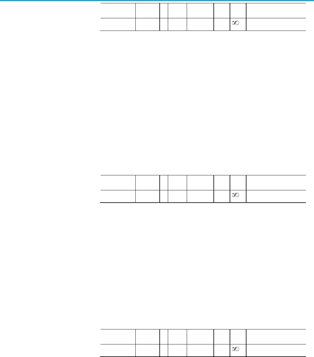
Chapter 4 CIP Axis Attributes
334 Rockwell Automation Publication MOTION-RM003O-EN-P - November 2023
Usage
Access
T
Data
Type
Default
Min
Max
Semantics of Values
Optional - C Set/SSV REAL 0.707 0
See Semantics
The Torque Notch Filter 2 Width attribute sets the damping ratio, Zd, in the
denominator of the torque notch filter equation that determines the width of
the notch for the third torque notch filter instance.
The frequency range over which signal attenuation is more than 3 dB can be
calculated as follows:
Width (Hz) = 2 * Notch Filter Frequency * Notch Filter Width * (1 - z
2
- .5z
4
-
z
6
).
Where,
z = Notch Filter Depth / Notch Filter Width
When Notch Depth is set to 0, z = 0.
Torque Notch Filter 3 Depth
Usage
Access
T
Data
Type
Default
Min
Max
Semantics of Values
Optional - C Set/SSV REAL 0 0
See Semantics
The Torque Notch Filter Depth attribute sets the damping ratio, Zn, in the
numerator of the torque notch filter equation that determines the depth of the
notch for the third torque notch filter instance.
The notch filter depth at the center frequency can be calculated as follows:
Depth (dB) = 20log10 (z).
Where,
z = Notch Filter Depth / Notch Filter Width
When Torque Notch Depth is set to 0, z = 0
Torque Notch Filter 3 Gain
Usage
Access
T
Data
Type
Default
Min
Max
Semantics of Values
Optional - C Set/SSV REAL 1 0
See Semantics
The Torque Notch Filter Gain attribute sets the high frequency gain of the
third torque notch filter instance. For notch filter operation, the value for this
attribute is set to 1. A value greater than one results in a lead-lag filter function
and a value less than one results in a lag-lead filter function. A value of 0
results in a low pass filter function.

Chapter 4 CIP Axis Attributes
Rockwell Automation Publication MOTION-RM003O-EN-P - November 2023 335
Torque Notch Filter 4 Width
Usage
Access
T
Data
Type
Default
Min
Max
Semantics of Values
Optional - C Set/SSV REAL 0.707 0
See Semantics
The Torque Notch Filter 2 Width attribute sets the damping ratio, Zd, in the
denominator of the torque notch filter equation that determines the width of
the notch for the fourth torque notch filter instance.
The frequency range over which signal attenuation is more than 3 dB can be
calculated as follows:
Width (Hz) = 2 * Notch Filter Frequency * Notch Filter Width * (1 - z
2
- .5z
4
-
z
6
).
Where,
z = Notch Filter Depth / Notch Filter Width
When Notch Depth is set to 0, z = 0.
Torque Notch Filter 4 Depth
Usage Access T Data
Type
Default Min Max Semantics of Values
Optional - C Set/SSV REAL 0 0
See Semantics
The Torque Notch Filter Depth attribute sets the damping ratio, Zn, in the
numerator of the torque notch filter equation that determines the depth of the
notch for the fourth torque notch filter instance.
The notch filter depth at the center frequency can be calculated as follows:
Depth (dB) = 20log10 (z).
Where,
z = Notch Filter Depth / Notch Filter Width
When Torque Notch Depth is set to 0, z = 0
Torque Notch Filter 4 Gain
Usage Access T Data
Type
Default Min Max Semantics of Values
Optional - C Set/SSV REAL 1 0
See Semantics
The Torque Notch Filter Gain attribute sets the high frequency gain of the
fourth torque notch filter instance. For notch filter operation, the value for
this attribute is set to 1. A value greater than one results in a lead-lag filter
function and a value less than one results in a lag-lead filter function. A value
of 0 results in a low pass filter function.

Chapter 4 CIP Axis Attributes
336 Rockwell Automation Publication MOTION-RM003O-EN-P - November 2023
Torque Limit - Positive
Usage
Access
T
Data
Type
Default
Min
Max
Semantics of Values
Required - C Set/SSV REAL 100
FD
0 10
3
% Motor Rated
This positive value determines the maximum positive torque that can be
applied to the motor. If the device attempts to exceed this value, the torque
command is clamped to this value.
Torque Limit - Negative
Usage
Access
T
Data
Type
Default
Min
Max
Semantics of Values
Required - C Set/SSV REAL -100
FD
-10
3
0 % Motor Rated
This negative value determines the most negative torque value that can be
applied to the motor. If the device attempts to apply a more negative torque
than this limit, the torque command is clamped to this value.
Torque Rate Limit
Usage
Access
T
Data
Type
Default
Min
Max
Semantics of Values
Optional - C Set/SSV REAL 10
6
0
% Motor Rated / Sec
Limits the rate of change of the torque reference signal.
Torque Threshold
Usage
Access
T
Data
Type
Default
Min
Max
Semantics of Values
Optional - C Set/SSV REAL 90
FD
0 10
3
% Motor Rated
Specifies the threshold for the Filtered Torque Reference signal magnitude
that when exceeded, results in the Torque Threshold status bit being set.
Overtorque Limit
Usage
Access
T
Data
Type
Default
Min
Max
Semantics of Values
Optional - D Set/SSV REAL 200 0 10
3
% Motor Rated
Maximum limit for the torque producing Iq Current Feedback signal
magnitude. When the Iq Current Feedback signal is greater than this value for

Chapter 4 CIP Axis Attributes
Rockwell Automation Publication MOTION-RM003O-EN-P - November 2023 337
the duration specified by the Overtorque Limit Time attribute, the result is an
Overtorque Limit exception. This feature lets the device generate an exception
if there is a sudden increase in load torque during operation. This condition
could occur if a bearing fails, a hard stop is reached, or there is some other
mechanical failure.
Overtorque Limit Time
Usage
Access
T
Data
Type
Default
Min
Max
Semantics of Values
Optional - D Set/SSV REAL 0 0 10
3
Seconds
Specifies the amount of time allowed in an Overtorque Limit condition before
generating an Overtorque Limit exception. A value of 0 for this attribute
disables the Overtorque feature.
Undertorque Limit
Usage
Access
T
Data
Type
Default
Min
Max
Semantics of Values
Optional - D Set/SSV REAL 10 0 10
3
% Motor Rated
Minimum limit for the torque producing Iq Current Feedback signal
magnitude. When the Iq Current Feedback is less than this value for the
duration specified by the Undertorque Limit Time attribute, the result is an
Undertorque Limit exception. This feature lets the device generate an
exception if there is a sudden decrease in load torque during operation. This
condition could occur, for example, if a load coupling breaks or a tensioned
web material breaks.
Undertorque Limit Time
Usage
Access
T
Data
Type
Default
Min
Max
Semantics of Values
Optional - D Set/SSV REAL 0 0 10
3
Seconds
Specifies the amount of time allowed in an Undertorque Limit condition
before generating an Undertorque Limit exception. A value of 0 for this
attribute disables the Undertorque feature.

Chapter 4 CIP Axis Attributes
338 Rockwell Automation Publication MOTION-RM003O-EN-P - November 2023
Torque Estimate Crossover Speed
Usage Access T Data
Type
Default Min Max Semantics of Values
Optional - C Set/SSV REAL 0.2*Eq 1 0
Velocity Units
The Torque Estimate Crossover Speed attribute is the speed at which the
Torque Estimator function transitions between two different estimation
methods used to calculate the Torque Estimate attribute value.
Torque Estimate Notch 1 Frequency
Usage Access T Data
Type
Default Min Max Semantics of Values
Optional - C Set/SSV REAL 100 0 10
4
Filter Frequency Units
The Torque Estimate Notch 1 Frequency attribute controls the center
frequency of the first notch filter instance applied to the output of the Torque
Estimator resulting in a filtered Torque Estimate signal. This object revision
of the CIP Motion specification supports up to 2 torque estimate notch filter
instances connected in series. A value of 0 for this attribute disables this filter
instance.
Torque Estimate Notch 1 Width
Usage
Access
T
Data
Type
Default
Min
Max
Semantics of Values
Optional - C Set/SSV REAL 1 0
See Torque Notch Filter
Semantics
The Torque Estimate Notch 1 Width attribute sets the damping ratio, Zd, in
the denominator of the notch filter equation that determines the width of the
notch of the first torque estimate notch filter instance.
The frequency range over which signal attenuation is more than 3 dB can be
calculated as follows:
Width (Hz) = 2 * Notch Filter Frequency * Notch Filter Width * (1 - z
2
- .5z
4
-
z
6
).
Where, z = Notch Filter Depth / Notch Filter Width
When Notch Filter Depth is set to 0, z = 0.

Chapter 4 CIP Axis Attributes
Rockwell Automation Publication MOTION-RM003O-EN-P - November 2023 339
Torque Estimate Notch 1 Depth
Usage
Access
T
Data
Type
Default
Min
Max
Semantics of Values
Optional - C Set/SSV REAL 0 0
See Torque Notch Filter
Semantics
The Torque Estimate Notch 1 Depth attribute sets the damping ratio, Zn, in
the numerator of the notch filter equation that determines the depth of the
notch of the first torque estimate notch filter instance.
The notch filter depth at the center frequency can be calculated as follows:
Depth (dB) = 20log10 (z). Where, z = Notch Filter Depth / Notch Filter Width
When Notch Filter Depth is set to 0, z = 0.
Torque Estimate Notch 1 Gain
Usage
Access
T
Data
Type
Default
Min
Max
Semantics of Values
Optional - C Set/SSV REAL 0 0
See Torque Notch Filter
Semantics
The Torque Estimate Notch 1 Gain attribute sets the high frequency gain of
the first torque estimate notch filter instance. For notch filter operation, the
value for this attribute is set to 1. A value greater than one results in a lead-lag
filter function and a value less than one results in a lag-lead filter function. A
value of 0 results in a low pass filter function.
Torque Estimate Notch 2 Frequency
Usage
Access
T
Data
Type
Default
Min
Max
Semantics of Values
Optional - C Set/SSV REAL 0 0 10
4
Filter Frequency Units
The Torque Estimate Notch 2 Frequency attribute controls the center
frequency of the second notch filter instance applied to the output of the
Torque Estimator resulting in a filtered Torque Estimate signal. This object
revision of the CIP Motion specification supports up to 2 torque estimate
notch filter instances connected in series. A value of 0 for this attribute
disables this filter instance.

Chapter 4 CIP Axis Attributes
340 Rockwell Automation Publication MOTION-RM003O-EN-P - November 2023
Torque Estimate Notch 2 Width
Usage
Access
T
Data
Type
Default
Min
Max
Semantics of Values
Optional - C Set/SSV REAL 0.707 0
See Torque Notch Filter
Semantics
The Torque Estimate Notch 2 Width attribute sets the damping ratio, Zd, in
the denominator of the notch filter equation that determines the width of the
notch of the second torque estimate notch filter instance.
The frequency range over which signal attenuation is more than 3 dB can be
calculated as follows:
Width (Hz) = 2 * Notch Filter Frequency * Notch Filter Width * (1 - z
2
- .5z
4
-
z
6
).
Where, z = Notch Filter Depth / Notch Filter Width
When Notch Filter Depth is set to 0, z = 0.
Torque Estimate Notch 2 Depth
Usage
Access
T
Data
Type
Default
Min
Max
Semantics of Values
Optional - C Set/SSV REAL 0 0
See Torque Notch Filter
Semantics
The Torque Estimate Notch 2 Depth attribute sets the damping ratio, Zn, in
the numerator of the notch filter equation that determines the depth of the
notch of the second torque estimate notch filter instance.
The notch filter depth at the center frequency can be calculated as follows:
Depth (dB) = 20log10 (z). Where, z = Notch Filter Depth / Notch Filter Width
When Notch Filter Depth is set to 0, z = 0.
Torque Estimate Notch 2 Gain
Usage
Access
T
Data
Type
Default
Min
Max
Semantics of Values
Optional - C Set/SSV REAL 1 0
See Torque Notch Filter
Semantics
The Torque Estimate Notch 2 Gain attribute sets the high frequency gain of
the second torque estimate notch filter instance. For notch filter operation,
the value for this attribute is set to 1. A value greater than one results in a

Chapter 4 CIP Axis Attributes
Rockwell Automation Publication MOTION-RM003O-EN-P - November 2023 341
lead-lag filter function and a value less than one results in a lag-lead filter
function. A value of 0 results in a low pass filter function.
Cogging Compensation Table
Usage
Access
T
Data
Type
Default
Min
Max
Semantics of Values
Optional - C Set/SSV Struct {
UINT,
REAL
[1024]
}
- - - Struct {
Length,
% Motor Rated [ ]
}
The Cogging Compensation Table is a list of values that represent the cogging
torque profile of the motor over one electrical cycle. The 0th element of the
array corresponds to an electrical angle of 0 degrees. An ideal motor with no
cogging would have a value of 100% for all elements in the array. A value above
100% would provide additional 1/Kt gain to the torque reference, while a value
below 100% would reduce the 1/Kt gain.
Torque Notch Low Pass Filter Bandwidth Min
Usage
Access
T
Data
Type
Default
Min
Max
Semantics of Values
Optional - C Set/SSV REAL Eq 18 1 10
4
Filter Frequency Units
The Torque Notch Low Pass Filter Bandwidth Min attribute sets the upper
limit on the Torque Notch Filter Frequency Estimate value for the Adaptive
Tuning function. The frequency of an identified natural resonance must be
lower than this limit to be applied to the Torque Notch Filter Frequency
Estimate.
Torque Notch Filter High Frequency Limit
Usage
Access
T
Data
Type
Default
Min
Max
Semantics of Values
Optional - C Set/SSV REAL FD 20 2*FD Filter Frequency Units
This value sets the upper limit on the Torque Notch Filter Frequency Estimate
value for the Adaptive Tuning function. The frequency of an identified natural
resonance must be lower than this limit to be applied to the Torque Notch
Filter Frequency Estimate.

Chapter 4 CIP Axis Attributes
342 Rockwell Automation Publication MOTION-RM003O-EN-P - November 2023
Torque Notch Filter Low Frequency Limit
Usage
Access
T
Data
Type
Default
Min
Max
Semantics of Values
Optional - C Set/SSV REAL FD 20 2000 Filter Frequency Units
This value sets the lower limit on the Torque Notch Filter Frequency Estimate
value for the Adaptive Tuning function. The frequency of an identified natural
resonance must be higher than this limit to be applied to the Torque Notch
Filter Frequency Estimate.
Torque Notch Filter Tuning Threshold
Usage
Access
T
Data
Type
Default
Min
Max
Semantics of Values
Optional - C Set/SSV T REAL 5 0 100 % Motor Rated
To be identified as a resonance frequency by the Adaptive Tuning function,
the resonance magnitude must exceed the Torque Notch Filter Tuning
Threshold. The magnitude of an identified natural resonance frequency must
be higher than this threshold value to be applied to the Torque Notch Filter
Frequency Estimate.
Torque Notch Filter Frequency Estimate
Usage
Access
T
Data
Type
Default
Min
Max
Semantics of Values
Optional - C Get T REAL - - - Radians/sec
This value represents the resonance frequency of the resonance having the
largest magnitude above the Torque Notch Filter Tuning Threshold. The value
is within the Torque Notch Filter Low Frequency Limit and the Torque Notch
Filter High Frequency Limit as identified during an Adaptive Tuning update.
Enabling the Tracking Notch Filter function triggers the value of the Notch
Filter Frequency Estimate to apply to the first instance of the Torque Notch
Filter.
Initiating a drive power cycle or reset triggers the value of the Torque Notch
Filter Frequency Estimate to initialize to the last known value stored in
nonvolatile memory.
When the Adaptive Tuning Configuration is changed to enable the Tracking
Notch Filter function, this attribute is initialized to the controller configured
Torque Notch Filter Frequency value.

Chapter 4 CIP Axis Attributes
Rockwell Automation Publication MOTION-RM003O-EN-P - November 2023 343
Torque Notch Filter Magnitude Estimate
Usage
Access
T
Data
Type
Default
Min
Max
Semantics of Values
Optional - C Get T REAL - - - % Motor Rated
This value represents the maximum magnitude for the resonant associated
with the Torque Notch Filter Frequency Estimate as identified by the Adaptive
Tuning update.
After a drive power cycle or reset, the value of this attribute is initialized to the
last known value stored in nonvolatile memory.
Torque Low Pass Filter Bandwidth Estimate
Usage
Access
T
Data
Type
Default
Min
Max
Semantics of Values
Optional - C Get T REAL - - - Radians/sec
This value represents the Bandwidth of the Torque Low Pass Filter when the
Adaptive Tuning Configuration is equal to Gain Stabilization or Tracking
Notch and Gain Stabilization. The Adaptive Tuning function modifies the
value. The value is initialized to the Torque Low Pass Filter Bandwidth when
the Adaptive Tuning Configuration transitions from Disabled or Tracking
Notch to Gain Stabilization or Tracking Notch and Gain Stabilization. The
Torque Low Pass Filter Bandwidth Estimate value is initialized to zero when
the drive is power cycled or reset.
Adaptive Tuning Gain Scaling Factor
Usage
Access
T
Data
Type
Default
Min
Max
Semantics of Values
Optional - PV Get/GSV T REAL - - - Applied Gain/Configured Gain
When the selected Adaptive Tuning Configuration has enabled the Gain
Stabilization function or Gain Optimization functions, this value
proportionally scales the servo loop gain attributes of the associated axis as
directed by the Adaptive Tuning function.
After a drive power cycle or reset, the value of this attribute is initialized to the
last known value stored in nonvolatile memory.
When the Adaptive Tuning Configuration is charged to disable the Gain
Stabilization function, this attribute is initialized to 1.

Chapter 4 CIP Axis Attributes
344 Rockwell Automation Publication MOTION-RM003O-EN-P - November 2023
Adaptive Tuning Gain Status
Usage
Access
T
Data
Type
Default
Min
Max
Semantics of Values
Optional - C Get/SSV T DWORD - - - Bitmap:
0: Torque Notch Filter
Frequency Detected
1: Torque Notch Filter Tune
Unsuccessful
2: Torque Notch Filter Multiple
Frequencies
3: Torque Notch Filter
Frequency Below Limit
4: Torque Notch Filter
Frequency Above Limit
5: Adaptive Tune Gain
Stabilization
6: Adaptive Tuning Gain
Optimization Timer Expired
7-31: Reserved
Bitmap containing adaptive tuning status bits.
The Torque Notch Filter Frequency Detected bit is set when resonances are
identified between the low and high frequency limits with magnitudes above
the tuning threshold. Otherwise, this bit is clear. This bit is also cleared when
the drive transitions to the Running state.
The Torque Notch Filter Tune Unsuccessful bit is set when the tracking notch
filters do not compensate all identified resonances. Otherwise, this bit is clear.
This bit is also cleared when the drive transitions to the Running state or
when adaptive tuning transitions from Disabled mode to one of the Tracking
Notch modes while in the Running state.
The Torque Notch Filter Multiple Frequencies bit is set when multiple
resonances are identified between the low and high frequency limits with
magnitudes above the tuning threshold. Otherwise, this bit is clear. This bit is
also cleared when the drive transitions to the Running state.
The Torque Notch Filter Frequency Below Limit bit is set when resonances are
identified below the low frequency limit with magnitudes above the tuning
threshold. Otherwise, this bit is clear. This bit is also cleared when the drive
transitions to the Running state.
The Torque Notch Filter Frequency Above Limit (bit 4) is set when resonances
are identified above the high frequency limit with magnitudes above the
tuning threshold. Otherwise, this bit is clear. This bit is also cleared when the
drive transitions to the Running state.
The Adaptive Tune Gain Stabilization bit is set when the gain scaling factor is
not equal to one, which indicates that adaptive tuning is controlling the low

Chapter 4 CIP Axis Attributes
Rockwell Automation Publication MOTION-RM003O-EN-P - November 2023 345
pass filter and adjusting servo loop gains to stabilize the system. Otherwise,
this bit is clear. This bit is also cleared when the drive transitions to the
Running state.
The Adaptive Tuning Gain Optimization Timer Expired bit is set when gain
optimization is disabled after the timer has expired. Otherwise, this bit is
cleared. Once this bit is set, the Adaptive Tuning Configuration automatically
switches from Gain Optimization to Gain Stabilization.
See also
Torque Force Control Signal Attributes on page 349
Velocity Control Mode on page 21
These are the Motor Adaptation attributes configuration attributes associated
with a Motion Control Axis.
Motor Adaption Speed
Usage
Access
T
Data
Type
Default
Min
Max
Semantics of Values
Optional - C Set - REAL - - % Motor Rated
The Motor Adaption Speed attribute sets the speed at which the motor
adaption functions become active. These functions include the torque, slip,
and flux adaption functions. Collectively, these functions are designed to
compensate for changes in motor performance due to temperature, speed,
current, and manufacturing variations.
The activation of the regulators associated with the slip and flux adaption
functions initiates a convergence period where the slip and flux regulator
errors are allowed to settle within a configured voltage level before slip and
flux compensation is applied.
Torque Adaption Enable
Usage
Access
T
Data
Type
Default
Min
Max
Semantics of Values
Optional - C Set - USINT - - - Enumerations:
0 = Disabled
1 = Enabled
The Torque Adaptation Enable attribute is the enumerated value used to
enable or disable the torque adaption function. This feature is used to
fine-tune the accuracy of the steady state torque produced by the motor by
using the current and voltage feedback signals, along with motor stator
resistance to convert the torque command to an Iq current command. When
Motor Adaptation Attributes

Chapter 4 CIP Axis Attributes
346 Rockwell Automation Publication MOTION-RM003O-EN-P - November 2023
disabled, the conversion between torque and current is a fixed scaling
factor-based motor parameter, which does not result in as accurate an applied
torque as when the feature is enabled.
Slip Adaption Enable
Usage
Access
T
Data
Type
Default
Min
Max
Semantics of Values
Optional - C
(Induction Motor)
E
Set - USINT - - - Enumerations:
0 = Disabled
1 = Enabled
The Slip Adaptation Enable attribute is the enumerated value used to enable
or disable the torque adaption function. This feature is used to fine-tune the
accuracy of the steady state torque produced by the motor by using the
current and voltage feedback signals, along with motor stator resistance to
convert the torque command to an Iq current command. When disabled, the
conversion between torque and current is a fixed scaling factor-based motor
parameter, which does not result in as accurate an applied torque as when the
feature is enabled.
Flux Adaption Enable
Usage
Access
T
Data
Type
Default
Min
Max
Semantics of Values
Optional - C Set - USINT - - - Enumerations:
0 = Disabled
1 = Enabled
The Flux Adaptation Enable attribute is the enumerated value used to enable
or disable the flux adaption feature. Internally, a flux regulator reduces the
flux current command in the field weakening region of the motor to help
prevent current loop instability and overvoltage faults when operating above
the base speed of the motor.
Torque Adaption Regulator Kp
Usage
Access
T
Data
Type
Default
Min
Max
Semantics of Values
Optional - C (PM
Motor)
Set - REAL - - - Internal Units
The Torque Adaption Regulator Kp attribute sets the proportional gain for the
torque regulator associated with the torque adaption function. Conceptually,
this regulator adds a trim signal to the current reference to improve the
accuracy of applied motor torque.

Chapter 4 CIP Axis Attributes
Rockwell Automation Publication MOTION-RM003O-EN-P - November 2023 347
Torque Adaption Regulator Ki
Usage
Access
T
Data
Type
Default
Min
Max
Semantics of Values
Optional - C (PM
Motor)
Set - REAL - - - Internal Units
The Torque Adaption Regulator Ki attribute sets the integral gain for the
torque regulator associated with the torque adaption function. Conceptually,
this regulator adds a trim signal to the current reference to improve the
accuracy of applied motor torque.
Torque Adaption Regulator Limit - Positive
Usage
Access
T
Data
Type
Default
Min
Max
Semantics of Values
Optional - C (PM
Motor)
Set - REAL - - - % Motor Rated
The Torque Adaption Regulator Limit - Positive attribute sets the positive
limit of the trim signal applied by the torque regulator associated with the
torque adaption function.
Torque Adaption Regulator Limit - Negative
Usage
Access
T
Data
Type
Default
Min
Max
Semantics of Values
Optional - C (PM
Motor)
Set - REAL - - - % Motor Rated
The Torque Adaption Regulator Limit - Negative attribute sets the negative
limit of the trim signal applied by the torque regulator associated with the
torque adaption function.
Slip and Flux Regulator Slew Time
Usage
Access
T
Data
Type
Default
Min
Max
Semantics of Values
Optional - C
(Induction Motor)
Set - REAL - - - Sec
The Slip and Flux Regulator Slew Time attribute determines the maximum
amount of time after the motor speed reaches the level specified by the Motor
Adaption Speed attribute that the slip and flux regulators are allowed to
converge before the slip and flux compensation provided by these regulators
are applied. If the regulators have not completed the convergence process in
the time specified by this attribute, the slip and flux compensation shall be
applied without further qualification.

Chapter 4 CIP Axis Attributes
348 Rockwell Automation Publication MOTION-RM003O-EN-P - November 2023
Slip and Flux Regulator Slew Rate
Usage
Access
T
Data
Type
Default
Min
Max
Semantics of Values
Optional - C
(Induction Motor)
Set - REAL - - - (Radians/sec)/(Amps/sec)
The Slip and Flux Regulator Slew Rate attribute determines the rate at which
the slip and flux regulators are allowed to converge.
Slip and Flux Regulator Convergence Level
Usage
Access
T
Data
Type
Default
Min
Max
Semantics of Values
Optional - C
(Induction Motor)
Set - REAL - - - Volts
The Slip and Flux Regulator Convergence Level attribute determines the level
that the slip and flux regulator voltage error must be within to indicate that
the regulators have converged.
Slip and Flux Regulator Convergence Time
Usage
Access
T
Data
Type
Default
Min
Max
Semantics of Values
Optional - C
(Induction Motor)
Set - REAL - - - Sec
The Slip and Flux Regulator Convergence Time attribute determines how long
the slip and flux regulator convergence condition must be maintained after
the convergence condition is first met before the slip and flux compensation
provided by the slip and flux regulators are applied. The convergence
condition is met when the regulator’s voltage error has decreased below the
level set in the Slip and Flux Regulator Converge Level attribute.
Slip Adaption Regulator Iq Threshold
Usage
Access
T
Data
Type
Default
Min
Max
Semantics of Values
Optional - C
(Induction Motor)
Set - REAL - - - % Motor Rated
The Slip Adaption Regulator Iq Threshold attribute sets for the torque
threshold above which the slip regulator of the slip adaption function becomes
active.

Chapter 4 CIP Axis Attributes
Rockwell Automation Publication MOTION-RM003O-EN-P - November 2023 349
Slip Adaption Regulator Kp
Usage
Access
T
Data
Type
Default
Min
Max
Semantics of Values
Optional - C
(Induction Motor)
Set - REAL - - - Motor Rated Slip/Volt
The Slip Adaption Regulator Kp attribute sets the proportional gain for the
slip regulator associated with the slip adaption function.
Slip Adaption Regulator Ki
Usage
Access
T
Data
Type
Default
Min
Max
Semantics of Values
Optional - C
(Induction Motor)
Set - REAL - - - (Motor Rated Slip/Volt)/Sec
The Slip Adaption Regulator Ki attribute sets the integral gain for the slip
regulator associated with the slip adaption function.
Flux Adaption Regulator Kp
Usage
Access
T
Data
Type
Default
Min
Max
Semantics of Values
Optional - C Set - REAL - - - Amps/Volt
The Flux Adaption Regulator Kp attribute sets the proportional gain for the
flux regulator associated with the flux adaption function.
Flux Adaption Regulator Ki
Usage
Access
T
Data
Type
Default
Min
Max
Semantics of Values
Optional - C Set - REAL - - - (Amps/Volt)/Sec
The Flux Adaption Regulator Ki attribute sets the integral gain for the flux
regulator associated with the flux adaption function.
See also
Torque/Force Control Configuration Attributes on page 316
These are the torque/force signal related attributes associated with a Motion
Control Axis.
Torque/Force Control
Signal Attrib

Chapter 4 CIP Axis Attributes
350 Rockwell Automation Publication MOTION-RM003O-EN-P - November 2023
Torque Command
Usage
Access
T
Data
Type
Default
Min
Max
Semantics of Values
Required - C Get/GSV T REAL -
-
% Motor Rated
Command torque output from fine interpolator (if active) into torque input
summing junction when configured for toque control.
Torque Trim
Usage
Access
T
Data
Type
Default
Min
Max
Semantics of Values
Required - C Set/SSV T REAL 0
-
% Motor Rated
Additional torque command added to the torque input summing junction.
Torque Reference
Usage
Access
T
Data
Type
Default
Min
Max
Semantics of Values
Required - C Get/GSV T REAL - - - % Motor Rated
Commanded torque reference input signal before torque filter section
representing the sum of the Torque Command and Torque Trim signal inputs.
Torque Reference Filtered
Usage
Access
T
Data
Type
Default
Min
Max
Semantics of Values
Required - C Get/GSV T REAL - - - % Motor Rated
Commanded torque reference input signal after torque filter section.
Torque Reference Limited
Usage
Access
T
Data
Type
Default
Min
Max
Semantics of Values
Required - C Get/GSV T REAL - - - % Motor Rated
Commanded torque reference input signal after torque limiter section.
Torque Estimate
Usage
Access
T
Data
Type
Default
Min
Max
Semantics of Values
Optional - C Get/GSV T REAL - - - % Motor Rated

Chapter 4 CIP Axis Attributes
Rockwell Automation Publication MOTION-RM003O-EN-P - November 2023 351
The Torque Estimate attribute is the estimated torque or force applied by the
motor. Conceptually, for PM motor types this signal is the product of the
torque constant, Kt, or force constant, Kf, and the Iq Current Feedback signal.
Other motor types might require more sophisticated torque or force
estimation algorithms.
See also
Torque Control Mode on page 23
Torque/Force Control Configuration Attributes on page 316
These are the velocity loop configuration attributes associated with a Motion
Control Axis.
Velocity Offset
Usage
Access
T
Data
Type
Default
Min
Max
Semantics of Values
Required - PV Set/SSV REAL 0 -maxspd maxspd Velocity Units
The Velocity Offset attribute can be used to provide a velocity bias when
performing velocity control. This value is summed together with the Velocity
Trim value that can be sent synchronously to the drive every Coarse Update
Period. Since the Velocity Trim value is available as a templated value,
real-time velocity corrections can be done using the Velocity Trim attribute.
Acceleration Feedforward Gain
Usage
Access
T
Data
Type
Default
Min
Max
Semantics of Values
Required - PV Set/SSV REAL 0 0
%
The Acceleration Feedforward Gain attribute is a value that multiplies the
Acceleration Fine Command signal to form the Acceleration Feedforward
Command that is applied to the acceleration loop summing junction. 100%
Acceleration Feedforward applies the full Acceleration Fine Command signal
to the output of the velocity loop.
Velocity Loop Bandwidth
Usage
Access
T
Data
Type
Default
Min
Max
Semantics of Values
Velocity Loop Config
Attributes

Chapter 4 CIP Axis Attributes
352 Rockwell Automation Publication MOTION-RM003O-EN-P - November 2023
Usage
Access
T
Data
Type
Default
Min
Max
Semantics of Values
Required - PV Set/SSV T REAL 260
FD
0
Loop Bandwidth Units
The Velocity Loop Bandwidth attribute is a value that determines the
proportional gain, Kvp, of the velocity loop that multiplies the Velocity Error
signal. This value represents the unity gain bandwidth of the velocity loop.
Velocity Integrator Bandwidth
Usage
Access
T
Data
Type
Default
Min
Max
Semantics of Values
Required - PV Set/SSV T REAL 0
FD
0
Loop Bandwidth Units
The Velocity Integrator Bandwidth attribute determines the velocity loop
integral gain, Kvi, which together with the Kvp, multiplies the integrated
Velocity Error signal. This value represents the bandwidth of the velocity
integrator beyond which the integrator is ineffective. A value of 0 for this
attribute disables the integrator.
Velocity Negative Feedforward Gain
Usage
Access
T
Data
Type
Default
Min
Max
Semantics of Values
Optional - PV Set/SSV REAL 0 0
%
The Velocity Negative Feedforward Gain attribute is a value that reduces
velocity overshoot by subtracting a portion of the velocity reference signal
from the velocity error.
Velocity Droop
Usage
Access
T
Data
Type
Default
Min
Max
Semantics of Values
Optional - FPV Set/SSV REAL 0 0
Velocity Units / Sec / %
Rated
Velocity Droop value that provides compliance with the velocity integrator by
subtracting a portion of the velocity loop effort from the velocity error input to
the velocity integrator. The presence of the Torque/Force scaling gain, Kj, in
the droop signal path lets Velocity Droop to be specified in velocity units per %
rated torque output. This parameter is also valid for V/Hz devices and its
behavior is nearly identical, but instead of % rated being related to torque, %
rated is related to current.

Chapter 4 CIP Axis Attributes
Rockwell Automation Publication MOTION-RM003O-EN-P - November 2023 353
Velocity Error Tolerance
Usage
Access
T
Data
Type
Default
Min
Max
Semantics of Values
Optional - PV Set/SSV REAL 0
FD
0
Velocity Units
The Velocity Error Tolerance attribute determines the absolute maximum
Velocity Error value that can be tolerated without causing an Excessive
Velocity Error exception.
Velocity Error Tolerance Time
Usage
Access
T
Data
Type
Default
Min
Max
Semantics of Values
Optional - PV Set/SSV REAL 0.01 0
Seconds
The Velocity Error Tolerance Time attribute determines the maximum
amount of time that the Velocity Error Tolerance can be exceeded without
generating an exception.
Velocity Integrator Control
Usage
Access
T
Data
Type
Default
Min
Max
Semantics of Values
Required - PV Set/SSV BYTE 0
0:0
1:0
- - Bitmap
0 = Integrator Hold
Enable (R)
1 = Auto-Preset (O)
2-7 = Reserved
The Velocity Integrator Control attribute controls the behavior of the velocity
loop integrator while commanding motion through the controller. When the
integrator hold enable bit is set, the integrator is held while motion is being
commanded with a non-zero velocity. When clear, the integrator runs without
qualification. When the auto-preset bit is set, the integrator preload value is
automatically loaded with the current torque command when there is a
control mode change between torque control and velocity control. If clear, the
integrator is loaded with the configured velocity integrator preload value.
Velocity Integrator Preload
Usage
Access
T
Data
Type
Default
Min
Max
Semantics of Values
Optional - PV Set/SSV REAL 0 0
Accel Units
The Velocity Integrator Preload attribute is a value assigned to the velocity
integrator when the velocity control loop is enabled.

Chapter 4 CIP Axis Attributes
354 Rockwell Automation Publication MOTION-RM003O-EN-P - November 2023
Velocity Low Pass Filter Bandwidth
Usage
Access
T
Data
Type
Default
Min
Max
Semantics of Values
Optional - PV Set/SSV T REAL 0 0 10
4
Filter Frequency Units
The Velocity Low Pass Filter Bandwidth attribute controls the bandwidth of
the Low Pass Filter applied to the Velocity Error signal. Recommended
implementation is a two pole IIR filter. A value of 0 for this attribute disables
this feature.
Velocity Threshold
Usage
Access
T
Data
Type
Default
Min
Max
Semantics of Values
Optional - ED Set/SSV REAL 0
FD
0
Velocity Units
The Velocity Threshold attribute defines a minimum absolute velocity. If the
magnitude of the Velocity Feedback signal is less than this value, the Velocity
Threshold status bit is set. If the axis is configured for Frequency Control, the
Velocity Feedback signal is derived from the Velocity Reference signal.
Velocity Lock Tolerance
Usage
Access
T
Data
Type
Default
Min
Max
Semantics of Values
Optional - PV Set/SSV REAL 1
FD
0
Velocity Units
The Velocity Lock Tolerance attribute establishes a window around the
unlimited velocity reference signal. When the Velocity Feedback signal is
within this window, the Velocity Lock status bit is set. When the Velocity
Feedback signal falls outside this window, the Velocity Lock status bit is
cleared.
Velocity Standstill Window
Usage
Access
T
Data
Type
Default
Min
Max
Semantics of Values
Required - ED Set/SSV REAL 1
FD
0
Velocity Units
The Velocity Standstill Window attribute establishes a window around zero
speed. When the Velocity Feedback signal is within this window, the Velocity
Standstill status bit is set. When the Velocity Feedback signal falls outside this
window, the Velocity Standstill status bit is cleared. If the axis is configured

Chapter 4 CIP Axis Attributes
Rockwell Automation Publication MOTION-RM003O-EN-P - November 2023 355
for Frequency Control, the Velocity Feedback signal is derived from the
Velocity Reference signal.
Velocity Limit - Positive
Usage
Access
T
Data
Type
Default
Min
Max
Semantics of Values
Optional - FPV Set/SSV REAL 0
FD
0
Velocity Units
The Velocity Limit - Positive attribute defines the most positive velocity
reference value into the velocity summing junction. If the signal entering the
velocity limiter exceeds this velocity limit value, the device responds by
clamping the velocity reference to this limit and sets the Velocity Limit status
bit.
Velocity Limit - Negative
Usage
Access
T
Data
Type
Default
Min
Max
Semantics of Values
Optional - FPV Set/SSV REAL 0
FD
-
0 Velocity Units
The Velocity Limit - Negative attribute is a negative value that defines the
most negative velocity reference value allowed into the velocity summing
junction. If the signal entering the velocity limiter exceeds this velocity limit
value, the device responds by clamping the velocity reference to this limit and
sets the Velocity Limit status bit.
Velocity Feedback Delay Compensation
Usage
Access
T
Data
Type
Default
Min
Max
Semantics of Values
Optional - PV Set/SSV REAL 0
0
0
Seconds
The Velocity Feedback Delay Compensation attribute sets the amount of
velocity feedback delay to apply to the feedback delay compensation function
that minimizes position error during acceleration and deceleration when
running in Position Control Mode. When needed, the attribute should be set
to the sum of the feedback sampling delay and the filter delays in the feedback
path.

Chapter 4 CIP Axis Attributes
356 Rockwell Automation Publication MOTION-RM003O-EN-P - November 2023
Slat Configuration
Usage
Access
T
Data
Type
Default
Min
Max
Semantics of Values
Optional - V Set/SSV BYTE 0 - - 0 = SLAT Disabled
1 = SLAT Min
Speed/Torque
2 = SLAT Max
Speed/Torque
The Slat Configuration attribute configures the Speed Limited Adjustable
Torque feature. The SLAT Configuration enumeration determines how the
drive controls torque for this axis instance. In order to support applications
that require Speed Limited Adjustable Torque (SLAT) control, the Min/Max
torque control enumerations provide a feature to switch to and from speed
control under certain conditions. In either SLAT mode, the drive will operate
in one of two min/max states - speed control off or on.
Bit
Name
Description
0
SLAT Disabled
SLAT function is disabled. Normal Velocity Loop operation.
1 SLAT Min Speed/Torque Drive will automatically switch from torque control to speed
control if Velocity Error < 0 and switch back to torque control if
Velocity Error > SLAT Setpoint for SLAT Time.
2 SLAT Max Speed/Torque Drive will automatically switch from torque control to speed
control if Velocity Error > 0 and switch back to torque control if
Velocity Error < -SLAT Set Point for SLAT Time
SLAT Set Point
Usage
Access
T
Data
Type
Default
Min
Max
Semantics of Values
Optional - V
Set/SSV
REAL
0
0
Velocity Units
Speed Error level to switch from Speed control to Min/ Max control.
SLAT Time Delay
Time delay after SLAT Set Point is reached to switch from Speed control to
Min/ Max control.
Usage
Access
T
Data
Type
Default
Min
Max
Semantics of Values
Optional - V Set/SSV REAL 0 0
Seconds
Time delay after SLAT Set Point is reached to switch from Speed control to
Min/ Max control.

Chapter 4 CIP Axis Attributes
Rockwell Automation Publication MOTION-RM003O-EN-P - November 2023 357
SLAT Min Speed/Torque Mode
In SLAT Min Speed/Torque mode (SLAT Configuration = 1) the drive defaults
to the state with speed control off (leftmost state) shown in the figure below.
In this state, the torque reference is the minimum, or Min function, of the
Velocity Loop Output or the Torque Command.
Min Mode
When used for SLAT control, an application-dependent Velocity Command is
applied to the drive. When the motor's speed is mechanically limited, this
reference is at a level that results in saturation of the velocity loop output. In
this state, the 'Min' select operation selects the smaller Torque Command
value. The Velocity Error is positive in value equal to the Velocity Command.
If the mechanical speed limitation is removed (example web break), the motor
accelerates and the Velocity Error becomes negative when the motor speed
exceeds the Velocity Command. At this time, an automatic transition to speed
control occurs and the Velocity Loop Output is selected as the Torque
Reference, regardless of the value of the Torque Command. Coincident with
the transition into speed control, a preset operation will occur within the
velocity loop. This preset will force the velocity loop integrator to match the
internal torque reference value, at the time of the mode transition.
In Min mode, the drive remains in speed control until the Velocity Error
exceeds the configured SLAT Set-point attribute value for a period given by
the SLAT Time Delay attribute. When these two conditions are met, speed
control is turned off and the 'Min' select operation becomes active. This
condition would occur if the mechanical constraint was restored.
SLAT Max Speed/Torque Mode
For SLAT Max Speed/Torque mode (SLAT Configuration = 2) the SLAT control
operates similar to SLAT Min Speed/Torque mode, except that the signs have
changed to allow the feature to work in the negative direction.
Max Mode

Chapter 4 CIP Axis Attributes
358 Rockwell Automation Publication MOTION-RM003O-EN-P - November 2023
The active 'Max' select function will select the larger, or Max function, of the
Velocity Loop Output or the Torque Command. The Velocity Command value
is a negative quantity and so when the motor speed is mechanically limited,
the Velocity Error is a negative value, and the Velocity Loop Output is a
saturated (limited) to a negative value. The Torque Command is also negative,
but smaller in magnitude, so it becomes selected by the 'Max' operation.
The forced transition to speed control occurs when the Velocity Error value
becomes positive such as when the mechanical limitation is removed. A preset
of the velocity loop's integral term occurs, as before.
When, by restoring the mechanical constraint, the Velocity Error becomes
negative again and less than the negated SLAT Set-point parameter value for a
SLAT Time delay, speed control is turned off and the 'Max' select operation
becomes active.
See also
Position Loop Attributes on page 309
Position Loop Configuration Attributes on page 312
Velocity Loop Attributes on page 358
These are the velocity control signal related attributes associated with a
Motion Control Axis.
Velocity Command
Usage
Access
T
Data
Type
Default
Min
Max
Semantics of Values
Required - FPV Get T REAL - - - Velocity Control
Units/Second
The Velocity Command attribute is the command velocity output from the
Fine Command Generator (if active) into the velocity loop when configured
for the Velocity Loop control or frequency controller when configured for
Frequency Control operation.
Velocity Loop Signal
Attributes

Chapter 4 CIP Axis Attributes
Rockwell Automation Publication MOTION-RM003O-EN-P - November 2023 359
Velocity Trim
Usage
Access
T
Data
Type
Default
Min
Max
Semantics of Values
Required - FPV Set T REAL 0 -maxspd maxspd Velocity Control
Units/Second
Additional velocity command added to the velocity loop summing junction.
Acceleration Feedforward Command
Usage
Access
T
Data
Type
Default
Min
Max
Semantics of Values
Required - PV Get T REAL - - - Velocity Control
Units/Sec
2
The Acceleration Feedforward Command attribute is an Acceleration
feedforward command signal that represents a scaled version of the
command acceleration profile. This signal is the Acceleration Fine Command
signal scaled by Kaff and applied to the output of the velocity loop.
Velocity Reference
Usage
Access
T
Data
Type
Default
Min
Max
Semantics of Values
Required - FPV
Get
T
REAL
-
-
-
Velocity Control
Units/Sec
Command velocity reference into the velocity loop summing junction, or in
the case of Frequency Control, the signal that is scaled to become the
Frequency Reference.
Velocity Feedback
Usage
Access
T
Data
Type
Default
Min
Max
Semantics of Values
Required - ED Get T REAL - - - Velocity Control
Units/Sec
Actual velocity of the axis that is applied to the velocity summing junction, if
applicable, based on Control Mode selection. In most cases, the Velocity
Feedback signal is derived directly from the feedback device specified by the
Feedback Mode selection. If the axis is configured for Feedback Only mode,
Velocity Feedback represents the actual velocity of the feedback device
specified by the Feedback Master Select. If the axis is configured for
Frequency Control, the Velocity Feedback signal is derived from the Velocity
Reference signal. If configured for Sensorless Velocity Loop operation, that is,

Chapter 4 CIP Axis Attributes
360 Rockwell Automation Publication MOTION-RM003O-EN-P - November 2023
Feedback Mode set to No Feedback, the sensorless control algorithm
estimates the Velocity Feedback.
Velocity Error
Usage
Access
T
Data
Type
Default
Min
Max
Semantics of Values
Required - PV Get T REAL - - - Velocity Control
Units/Sec
Error between the velocity reference and velocity feedback value that is the
output of the velocity loop summing junction.
Velocity Integrator Output
Usage
Access
T
Data
Type
Default
Min
Max
Semantics of Values
Required - PV Get T REAL - - - Accel Control Units/Sec
2
Output of velocity integrator representing the contribution of the velocity
integrator to Velocity Loop Output.
Velocity Loop Output
Usage Access T Data
Type
Default Min Max Semantics of Values
Required - PV Get T REAL - - - Accel Control Units/Sec
2
Output of velocity forward path representing the total control effort of the
velocity loop.
Velocity Limit Source
Usage
Access
T
Data
Type
Default
Min
Max
Semantics of Values
Optional- PV Get T USINT - - - Enumeration:
0 = Not Limited
1 = Positive Limit
2 = Negative Limit
3 = Bus Overvoltage
Limit
4 = Max Extended Speed
Limit
5 - 127 = Reserved
128 – 255 = Vendor
Specific

Chapter 4 CIP Axis Attributes
Rockwell Automation Publication MOTION-RM003O-EN-P - November 2023 361
The Velocity Limit Source attribute is an enumerated value that specifies the
source of the operative velocity limit.
Velocity Limiter Extensions
Permanent magnet (PM) motor applications sometimes require drives to
provide extensions to the velocity limiter function to protect the drive
electronics and motor from potentially destructive overspeed conditions
when operating at speeds above the motor's rating. The Velocity Limiter
serves to protect the drive and motor when applied in these high-speed
applications.
PM Motor Torque-Speed Curve
A generalized Torque-Speed curve for a PM motor is shown in the following
graph. The two curves shown define the continuous (T
c
) and peak torque (T
p
)
capabilities of the motor. PM motors typically specify a 'rated speed' (S
r
) based
on rated voltage and continuous torque and a 'max speed' (S
m
) based on the
maximum operating speed. Often the specified rated speed and max speed for
the motor are set to the same value.
Field Weakening
PM motors can also be operated using a technique called "field weakening" to
extend the top speed capability of the motor. Field weakening uses active
current vector control to reduce the effective magnetic field strength from the
permanent magnets, enabling higher speeds at the expense of lower torque
production. While the use of field weakening to extend motor speed range is
more common for Interior PM (IPM) motors, the speed range of
Surface-mount PM (SPM) motors can be extended as well. The following
graph illustrates the PM Motor Torque-Speed Curve with Field Weakening.

Chapter 4 CIP Axis Attributes
362 Rockwell Automation Publication MOTION-RM003O-EN-P - November 2023
When the drive applies field weakening to a PM motor to reach higher than
rated speed, the drive's motor current vector control algorithm effectively
decreases the motor Ke. This reduces the resulting Counter EMF (CEMF)
voltage to be less than the DC bus voltage. However, if this active current
vector control is suddenly removed, the Ke value would revert to the nominal
value and the CEMF voltage would increase rapidly. Active control of motor
current is lost whenever the power structure is disabled. So the concern is
when the power structure is disabled with the motor still spinning. This can
be the case when the drive executes a Category 0 Stop due to a control
initiated Disable Request, a Major Fault action, or a Safe Torque Off
activation.
Three speed values are shown in the preceding figure. As defined in the first
figure, the rated speed (S
r
) corresponds to operation at rated voltage and
continuous torque. This is the maximum continuous torque that can be
achieved without field weakening. S
OV
is the speed at which the CEMF voltage
from the nominal Ke would be equivalent to the maximum DC Bus Voltage
rating of the drive, or the DC Bus Overvoltage Limit.
If active motor current control is removed while the motor is operating at
speeds above S
OV
, the CEMF voltage results in a DC Bus overvoltage condition
that can damage the drive and, possibly, other drives sharing the DC Bus.
S
m
is the absolute maximum operating speed of the motor based on
mechanical constraints. For a rotary motor, the Rotary Motor Max Speed
attribute gives the S
m
.
Major damage to devices connected to the DC Bus can occur when the PM
motor is allowed to run between S
OV
and S
m
and the drive's power structure is
disabled.
Velocity Limiter Behavior Diagram
The following diagram shows the extensions that have been added to the
Velocity Limiter to help manage the inherent risks of high-speed PM motor
operation. In addition to the existing Velocity Limit - Positive/Negative
attributes that can be used to limit the Velocity Reference signal, two new
limits have been defined based on S
OV
and S
m
defined above. Specifically, the

Chapter 4 CIP Axis Attributes
Rockwell Automation Publication MOTION-RM003O-EN-P - November 2023 363
PM Motor Rotary - Bus Overvoltage Speed and PM Motor Linear Bus
Overvoltage Speed attributes establish an absolute limit on the Velocity
Reference signal that corresponds to S
OV
. This speed limit can only be
exceeded if the PM Motor Extended Speed Permissive attribute is set to True.
The PM Motor Rotary Max Extended Speed and PM Motor Linear Max
Extended Speed attributes establish an absolute limit on the Velocity
Reference signal that corresponds to S
m
. The Velocity Limit function limits the
Velocity Reference signal to the minimum of these attribute values. The
Velocity Limit Source attribute indicates the source of the velocity limit.
Through these extensions to the Velocity Limiter function, a drive that
supports field weakening can be configured to manage extended speed
operation, only allowing operation above S
OV
by setting the PM Motor
Extended Speed Permissive attribute. Systems that can run safely above S
OV
are equipped with a DC Bus Regulator or a Resistive Brake Module.
See also
Position Loop Signal Attributes on page 309
Position Loop Configuration Attributes on page 312
Velocity Loop Configuration Attributes on page 351
General Permanent Magnet Motor Attributes on page 622
These attribute tables contain attributes associated with general data of the
Motion Control Axis Object instance.
These are the attributes that provide information about the associated
hardware capabilities of the Motion Control Axis.
Inverter Rated Output Voltage
Usage
Access
T
Data
Type
Default
Min
Max
Semantics of Values
Data Attributes
Axis Info Attributes

Chapter 4 CIP Axis Attributes
364 Rockwell Automation Publication MOTION-RM003O-EN-P - November 2023
Usage
Access
T
Data
Type
Default
Min
Max
Semantics of Values
Required - D
Optional - X
!LTM
Get REAL - - - Volts (RMS)
The Inverter Rated Output Voltage attribute is the drive inverter output
voltage rating. This value is hard coded in the device.
Inverter Rated Output Current
Usage
Access
T
Data
Type
Default
Min
Max
Semantics of Values
Required - D
Optional - X
!LTM
Get REAL - - - Amps (RMS)
The Inverter Rated Output Current attribute is the drive inverter output
current rating. This value is hard coded in the device.
Inverter Rated Output Power
Usage Access T Data
Type
Default Min Max Semantics of Values
Required - D
Optional - X
!LTM
Get
REAL
-
-
-
Kilowatts
The Inverter Rated Output Power attribute is the drive inverter output power
rating. This value is hard coded in the device.
Converter Rated Output Current
Usage
Access
T
Data
Type
Default
Min
Max
Semantics of Values
Optional - BD Get REAL - - - Amps
The Converter Rated Output Current attribute is the converter output current
rating.
Converter Rated Output Power
Usage Access T Data
Type
Default Min Max Semantics of Values
Optional - BD Get REAL - - - Kilowatts

Chapter 4 CIP Axis Attributes
Rockwell Automation Publication MOTION-RM003O-EN-P - November 2023 365
The Converter Rated Output Power attribute is the converter output power
rating.
Converter Rated Output Voltage
Usage
Access
T
Data
Type
Default
Min
Max
Semantics of Values
Optional - BD Get REAL - - - Volts
The Converter Rated Output Voltage attribute is the converter output voltage
rating.
Converter Rated Input Current
Usage
Access
T
Data
Type
Default
Min
Max
Semantics of Values
Optional - BD Get REAL - - - Amps (RMS)
The Converter Rated Input Current attribute is the converter input current
rating.
Converter Rated Input Power
Usage
Access
T
Data
Type
Default
Min
Max
Semantics of Values
Optional - BD Get REAL - - - Kilowatts
The Converter Rated Input Power attribute is the converter input power
rating.
Converter Rated Input Voltage
Usage
Access
T
Data
Type
Default
Min
Max
Semantics of Values
Optional - BD Get REAL - - - Volts (RMS)
The Converter Rated Input Voltage attribute is the converter input voltage
rating.
Drive Power Structure Axis ID
Usage
Access
T
Data
Type
Default
Min
Max
Semantics of Values
Optional - D Get UDINT - - - ID#
The Drive Power Structure Axis ID attribute identifies the power structure
with the axis instance.

Chapter 4 CIP Axis Attributes
366 Rockwell Automation Publication MOTION-RM003O-EN-P - November 2023
See also
Drive Output Attributes on page 395
Power and Thermal Management Configuration Attributes on page
406
Converter Current Reference Signal Attributes on page 745
These are the frequency analysis configuration attributes associated with a
Motion Control Axis.
Frequency Analysis Status
Usage
Access
Data
Type
Default
Min
Max
Semantics of Values
Optional - GC Get USINT Enumeration:
0 = Inactive
1 = Configuring System
2 = Collecting Data
3 = Analyzing Data
4 = Data Ready
5-255 = (reserved)
Enumeration showing the status of frequency analysis process.
Waterfall Index
Usage
Access
Data
Type
Default
Min
Max
Semantics of Values
Optional - GC Get USINT Range: 0 to 1000
Specifies the index into the Output Frequency array that is associated with the
singular input frequency applied during the last frequency analysis test. This
attribute is only applicable when the frequency analysis test was using the
Waterfall Excitation Type.
Frequency Samples
Usage
Access
Data
Type
Default
Min
Max
Semantics of Values
Optional - GC Get USINT Range: 1 to 1000
Specifies the number of measured frequencies.
Frequency Analysis
Attributes

Chapter 4 CIP Axis Attributes
Rockwell Automation Publication MOTION-RM003O-EN-P - November 2023 367
Output Frequency
Usage
Access
Data
Type
Default
Min
Max
Semantics of Values
Optional - GC Get REAL
[200]
Hertz
List of frequencies measured during frequency analysis test. The list begins at
the Start frequency and ends with the Stop frequency.
Output Magnitude
Usage
Access
Data
Type
Default
Min
Max
Semantics of Values
Optional - GC Get REAL
[200]
Decibels
List of output magnitudes measured at frequencies listed in the Output
Frequency array. Decibel units are defined as 20*log10 of the ratio of
measured output amplitude over the input excitation amplitude.
Output Phase
Usage
Access
Data
Type
Default
Min
Max
Semantics of Values
Optional - GC Get REAL
[200]
Degrees
List of output phase shift measured relative to input excitation at frequencies
listed in the Output Frequency array.
Gain Margin
Usage
Access
Data
Type
Default
Min
Max
Semantics of Values
Optional - GC Get REAL
Decibels
A measure of stability that can be computed when the Analysis Type of the
Run Frequency Analysis service request equals one or two. The value is the
magnitude [dB] when the phase is equal to -180ᵒ. The attribute value is
interpolated based on the Output Magnitude array.
Gain Margin Frequency
Usage
Access
Data
Type
Default
Min
Max
Semantics of Values

Chapter 4 CIP Axis Attributes
368 Rockwell Automation Publication MOTION-RM003O-EN-P - November 2023
Usage
Access
Data
Type
Default
Min
Max
Semantics of Values
Optional - GC Get REAL
Hertz
The frequency associated with the Gain Margin. The attribute value is
interpolated based on the Output Frequency array.
Phase Margin
Usage
Access
Data
Type
Default
Min
Max
Semantics of Values
Optional - GC Get REAL
Degrees
A measure of stability that can be computed when the Analysis Type of the
Run Frequency Analysis service request equals 1 or 2. The measure is the
phase [degrees] when the magnitude is equal to 0 dB. The attribute value is
interpolated based on the Output Phase array.
Phase Margin Frequency
Usage
Access
Data
Type
Default
Min
Max
Semantics of Values
Optional - GC Get REAL
Hertz
The frequency associated with the Phase Margin. The value is attribute is
interpolated based on the Output Frequency array.
Closed Loop Bandwidth
Usage
Access
Data
Type
Default
Min
Max
Semantics of Values
Optional - GC Get REAL
Hertz
The interpolated Output Frequency where the interpolated Output Magnitude
has a -3 dB crossing. If there are multiple -3 dB crossings, the lowest frequency
is chosen. This attribute is valid for Position Closed Loop, Velocity Closed
Loop, and Current Closed Loop frequency analysis test, otherwise the value is
set to zero.
See also
Axis Info Attributes on page 363
These are the data logging attributes associated with a Motion Control Axis.
Data Logging Attributes

Chapter 4 CIP Axis Attributes
Rockwell Automation Publication MOTION-RM003O-EN-P - November 2023 369
Data Logging Status
Usage
Access
Data
Type
Default
Min
Max
Semantics of Values
Optional - All Get USINT Enumeration:
0 = Inactive
1 = Buffering
2 = Buffered & Armed
3 = Triggered & Collecting
4 = Collected
5-255 = (reserved)
Enumeration showing the status of the data collection process.
Data Trigger Time Stamp
Usage
Access
Data
Type
Default
Min
Max
Semantics of Values
Optional - All Get LINT Nanoseconds
Time Stamp associated with the data logging trigger event.
Data Trigger Index
Usage
Access
Data
Type
Default
Min
Max
Semantics of Values
Optional - All Get UINT Index: 0 to 999
Index location in the data log of the sample associated with the trigger event.
Data Log 1
Usage
Access
Data
Type
Default
Min
Max
Semantics of Values
Optional - All Get LINT*
[N]
Units of associated data
source attribute.
General-purpose array type attribute for storing sampled real-time axis data.
* 64-bit data container can be used to transfer any data type associated with
Attribute ID. Data Types less than 64-bits shall be the least significant word
aligned with no sign extension. Size of the array is left to vendors discretion.
Data Log 2
Usage
Access
Data
Type
Default
Min
Max
Semantics of Values

Chapter 4 CIP Axis Attributes
370 Rockwell Automation Publication MOTION-RM003O-EN-P - November 2023
Usage
Access
Data
Type
Default
Min
Max
Semantics of Values
Optional - All Get LINT*
[N]
Units of associated data
source attribute.
General-purpose array type attribute for storing sampled real-time axis data.
* 64-bit data container can be used to transfer any data type associated with
Attribute ID. Data Types less than 64-bits shall be the least significant word
aligned with no sign extension. Size of the array is left to vendor's discretion.
Data Log 3
Usage
Access
Data
Type
Default
Min
Max
Semantics of Values
Optional - All Get LINT*
[N]
Units of associated data
source attribute.
General-purpose array type attribute for storing sampled real-time axis data.
* 64-bit data container can be used to transfer any data type associated with
Attribute ID. Data Types less than 64-bits shall be the least significant word
aligned with no sign extension. Size of the array is left to vendor's discretion.
Data Log 4
Usage
Access
Data
Type
Default
Min
Max
Semantics of Values
Optional - All Get LINT*
[N]
Units of associated data
source attribute.
General-purpose array type attribute for storing sampled real-time axis data.
* 64-bit data container can be used to transfer any data type associated with
Attribute ID. Data Types less than 64-bits shall be the least significant word
aligned with no sign extension. Size of the array is left to vendor's discretion.
Data Log 5
Usage
Access
Data
Type
Default
Min
Max
Semantics of Values
Optional - All Get LINT*
[N]
Units of associated data
source attribute.
General-purpose array type attribute for storing sampled real-time axis data.
* The 64-bit data container can be used to transfer any data type associated
with the Attribute ID. Data Types less than 64 bits shall be the least significant

Chapter 4 CIP Axis Attributes
Rockwell Automation Publication MOTION-RM003O-EN-P - November 2023 371
word aligned with no sign extension. Size of the array is left to vendor's
discretion.
Data Log 6
Usage
Access
Data
Type
Default
Min
Max
Semantics of Values
Optional - All Get LINT*
[N]
Units of associated data
source attribute.
General-purpose array type attribute for storing sampled real-time axis data.
* The 64-bit data container can be used to transfer any data type associated
with the Attribute ID. Data Types less than 64 bits shall be the least significant
word aligned with no sign extension. Size of the array is left to vendor's
discretion.
Data Log 7
Usage
Access
Data
Type
Default
Min
Max
Semantics of Values
Optional - All Get LINT*
[N]
Units of associated data
source attribute.
General-purpose array type attribute for storing sampled real-time axis data.
* The 64-bit data container can be used to transfer any data type associated
with the Attribute ID. Data Types less than 64 bits shall be the least significant
word aligned with no sign extension. Size of the array is left to vendor's
discretion.
Data Log 8
Usage
Access
Data
Type
Default
Min
Max
Semantics of Values
Optional - All Get LINT*
[N]
Units of associated data
source attribute.
General-purpose array type attribute for storing sampled real-time axis data.
* The 64-bit data container can be used to transfer any data type associated
with the Attribute ID. Data Types less than 64 bits shall be the least significant
word aligned with no sign extension. Size of the array is left to vendor's
discretion.

Chapter 4 CIP Axis Attributes
372 Rockwell Automation Publication MOTION-RM003O-EN-P - November 2023
Data Capture Size
Usage
Access
Data
Type
Default
Min
Max
Semantics of Values
Optional - All Get UINT
Units of associated data
source attribute.
Specifies the number of samples captured in each active Data Log. This
number can be no larger than the size of the Data Log arrays.
See also
Axis Info Attributes on page 363
Frequency Analysis Attributes on page 366
These are the attributes that provide useful statistics on motion axis
operation.
Control Power-up Time
Usage
Access
T
Data
Type
Default
Min
Max
Semantics of value
Optional - XBD
Get/GSV
REAL
-
-
-
Seconds
Elapsed time since the axis control power was last applied.
Cumulative Run Time
Usage
Access
T
Data
Type
Default
Min
Max
Semantics of value
Optional - XBD
Get/GSV
REAL
-
-
-
Hours
Accumulated time that the axis has been powering the Running state.
Cumulative Energy Usage
Usage
Access
T
Data
Type
Default
Min
Max
Semantics of value
Optional - XBD
Get/GSV
REAL
-
-
-
Kilowatt Hours
Accumulated output energy of the axis.
Cumulative Motor Rev
Usage
Access
T
Data
Type
Default
Min
Max
Semantics of value
Optional - D
Get/GSV
LINT
-
-
-
Axis Statistical Attributes

Chapter 4 CIP Axis Attributes
Rockwell Automation Publication MOTION-RM003O-EN-P - November 2023 373
Cumulative number of times the motor shaft has turned. (Rotary Motors
Only).
Cumulative Main Power Cycles
Usage
Access
T
Data
Type
Default
Min
Max
Semantics of value
Optional - XBD
Get/GSV
DINT
-
-
-
Cumulative number of times AC Mains has been cycled.
Cumulative Control Power Cycles
Usage
Access
T
Data
Type
Default
Min
Max
Semantics of value
Optional - XBD
Get/GSV
DINT
-
-
-
Cumulative number of times Control Power has been cycled.
Cumulative Control Power-Up Time
Usage
Access
T
Data
Type
Default
Min
Max
Semantics of value
Optional - XBD
Get/GSV
REAL
-
-
-
Hours
Accumulated time that control power has been applied.
See also
Interpret the Attribute Tables on page 103
These are the device status attributes associated with a Motion Control Axis.
Any status bits that are not applicable are set to 0.
Axis State
Usage
Access
T
Data
Type
Default
Min
Max
Semantics of Values
CIP Axis Status Attributes

Chapter 4 CIP Axis Attributes
374 Rockwell Automation Publication MOTION-RM003O-EN-P - November 2023
Usage
Access
T
Data
Type
Default
Min
Max
Semantics of Values
Required - All Get T USINT - - - Enumeration:
0 = Initializing
1 = Pre-Charge
2 = Stopped
3 = Starting
4 = Running
5 = Testing
6 = Stopping
7 = Aborting
8 = Major Faulted
9 = Start Inhibited
10 = Shutdown
11-255: Reserved
Enumerated value indicating the state of the axis.
Axis Status
Usage
Access
T
Data Type
Default
Min
Max
Semantics of Values
Required - All Get T DWORD - - - See Semantics
The Axis Status attribute is a collection of standard bits indicating the internal
status of the axis.
Axis Status 2
Usage
Access
T
Data Type
Default
Min
Max
Semantics of Values
Required - XG
Opt - NED
Get T DWORD - - - See Semantics
The Axis Status 2 attribute is a collection of standard bits that indicate the
internal status of the axis. The attribute provides a 32-bit extension to the CIP
Axis Status attribute.
Axis Status 2 - Mfg
Usage
Access
T
Data Type
Default
Min
Max
Semantics of Values
Required - All Get T DWORD - - - Bitmap:
0-31: Vendor Specific
(Published in Product Manual)
The Axis Status 2 - Mfg attribute is a collection of vendor-specific bits
indicating the internal status of the axis. This attribute provides a 32-bit
extension to the Axis Status Mfg attribute.

Chapter 4 CIP Axis Attributes
Rockwell Automation Publication MOTION-RM003O-EN-P - November 2023 375
CIP Status Bit Descriptions
Bit
Usage
Status Condition
Description
0 Required Local Control This bit is set if the axis is taking command reference
and services from the local interface instead of the
remote (CIP Motion) interface. This bit is based on the
current state of the Remote Mode bit of the Node
Status attribute.
1 Required Alarm This bit is set if the axis has detected one or more
exception conditions configured to generate an alarm.
This bit is clear if there are no current axis alarm
conditions.
2 Required/
XBD
DC Bus Up For a drive axis, this bit is set if the DC Bus has
charged up to an operational voltage level based on
direct measurement and, if applicable, the Converter
Bus Up Status bit associated with the external CIP
Motion converter) supplying DC Bus power to this
device is also set. If the Bus Configuration attribute is
set to
Shared DC - Non CIP Converte
r the drive might
also check the status of its associated external
Non-CIP Motion converter. When a drive axis is in the
Pre-Charge state, the transition of the DC Bus Up
status bit from 0 to 1 initiates a state transition to the
Stopped State. Once set, the DC Bus Up bit is cleared
when the DC Bus voltage has dropped below an
operational voltage level, or the Converter Bus Up
Status bit associated with external CIP Motion
converters supplying DC Bus power to this device is
cleared.
For an AC/DC converter axis, this bit is set if the DC
Bus has charged up to an operational voltage level
based on direct measurement alone. When a converter
axis is in the Pre-Charge state, the transition of the DC
Bus Up status bit from 0 to 1 initiates a state transition
to the Running state for a Passive converter, or to the
Stopped state for an Active converter. Once set, the DC
Bus Up bit is cleared when the DC Bus voltage has
dropped below an operational voltage level,
independent of the state of the Converter Bus Up
Status bit.
For a DC/DC converter axis, this bit is set when the
primary DC Bus has charged up to an operational
voltage level based on direct measurement, the
Converter Bus Up Status bit associated with external
CIP Motion converters supplying DC Bus power to this
device has been set, and the DC/DC converter has
established all the secondary DC Bus voltage levels.
While the DC/DC converter axis is in the Pre-Charge
state, the transition of the DC Bus Up status bit from 0
to 1 initiates a state transition to the Running state.

Chapter 4 CIP Axis Attributes
376 Rockwell Automation Publication MOTION-RM003O-EN-P - November 2023
Bit
Usage
Status Condition
Description
3 Required/
XGD O/N
Power Structure
Enabled
This bit is set if the axis power structure is energized
and capable of generating motor flux and torque for a
drive axis, or regenerating power to the AC line for a
converter axis. The value of the Power Structure
Enabled bit is determined by the Axis State, and for
the drive axis, the configured Stopping Action
attribute value.
4 Required/
D
Motor Flux Up This bit is set if the motor flux for an induction motor
has reached an operational level. Transition of the
Motor Flux Up bit is initiated in the Starting State
according to the configured Flux Up Control attribute
value. This bit is only applicable to Induction Motor
types.
5
Required/
XGD
Tracking
Command
This bit is set if the axis control structure is actively
tracking the command reference from the motion
planner associated with a drive axis, or the bus
voltage setpoint of a converter axis, or the current
references of a track section axis applying force to
resident movers. The Tracking Command bit is directly
associated with the Running state of the Axis State
Model.
6 Required/
P
Position Lock This bit is set if the actual position is within the
Position Lock Tolerance of the command position.
7 Optional/
PV
Velocity Lock This bit is set if the velocity feedback signal is within
the Velocity Lock Tolerance of the unlimited velocity
reference.
8 Required/
ED
Velocity Standstill This bit is set if the velocity feedback signal is within
the Velocity Standstill Window of 0. For a Frequency
Control drive, this bit is set if the velocity reference
signal is within the Velocity Standstill Window of 0.
9 Optional/
ED
Velocity Threshold This bit is set if the absolute velocity feedback signal
is below Velocity Threshold. For a Frequency Control
drive, this bit is set if the absolute velocity reference
signal is below the Velocity Threshold.
10 Optional/
FPV
Velocity Limit This bit is set if the velocity reference signal is limited
by the Velocity Limiter.
11 Optional/
C
Acceleration Limit This bit is set if the acceleration reference signal is
limited by the Acceleration Limiter.
12 Optional/
C
Deceleration Limit This bit is set if the acceleration reference signal is
limited by the Deceleration Limiter.
13 Optional/
C
Torque Threshold This bit is set if the absolute filtered torque reference
is above the Torque Threshold.
14 Required/
C
Torque Limit This bit is set if the filtered torque reference is limited
by the Torque Limiter.
15 Optional/
XD
Current Limit This bit is set if the command current, Iq, is limited by
the Current Vector Limiter.
16 Optional/
XD
Thermal Limit This bit is set if the Current Vector Limit condition of
the axis is limited by any of the axis's Thermal Models
or I
2
T Thermal Protection functions.

Chapter 4 CIP Axis Attributes
Rockwell Automation Publication MOTION-RM003O-EN-P - November 2023 377
Bit
Usage
Status Condition
Description
17 Required/
RE
Feedback Integrity This bit, when set, indicates that the feedback device
is accurately reflecting changes to axis position, and
there have been no conditions detected that would
compromise the quality of the feedback position
value. The bit is set at power-up assuming that the
feedback device passes any power-up self-test
required. If during operation a feedback exception
occurs that could impact the fidelity of axis position,
the bit is immediately cleared. The bit remains clear
until either a fault reset is executed by the drive or the
drive is power cycled. The Feedback Integrity bit
behavior applies to both absolute and incremental
feedback device operation.
18 Required/
XBD
Shutdown This bit is set when the axis is in the shutdown state
or in the faulted state but would transition to the
shutdown state if the faults were cleared. Therefore,
the Shutdown bit is closely associated with the
Shutdown State of the Axis State Model.
19 Required In Process This bit is set for the duration of an active process. An
example of an active process would be an operation
initiated by a Run Motor Test, Run Hookup Test, or Run
Inertia Test to request service. An active process that
requires the enabling of the axis power structure
results in a transition to the Testing State of the Axis
State Model.

Chapter 4 CIP Axis Attributes
378 Rockwell Automation Publication MOTION-RM003O-EN-P - November 2023
Bit
Usage
Status Condition
Description
20 Optional/
XBD
DC Bus Unload This bit is set by a CIP Motion converter, or a CIP
Motion drive containing an integral converter, or a CIP
Motion drive connected to an external non-CIP
converter, to indicate that the converter cannot
continue supplying DC Bus power to other drives and
converters on a shared DC Bus. This is usually the
result of a shutdown fault action initiated by the drive
or converter, or a shutdown request from the
controller. When the DC Bus Unload bit is set, the
Shutdown bit (bit 18) in this case is also set. A start
inhibit condition can also set the DC Bus Unload bit.
When there is no AC Contactor Enable output to drop
the DC Bus, a method is needed to unload the
converter from all other drives and converters sharing
the DC Bus. By monitoring the DC Bus Unload status
bit, the control system uses the Converter Bus Unload
bit of Control Status to initiate Bus Power Sharing
exceptions on all enabled drives on the shared DC Bus
that are configured for Shared AC/DC or Shared DC
operation. This Bus Power Sharing exception invokes
the configured Exception Action that, by default,
disables the device’s power structure and unloads the
bus. Upon receiving a Converter Bus Unload, all
disabled drives sharing the DC Bus shall indicate a
Converter Bus Unload start inhibit.
Unlike other devices, DC/DC converters configured for
Shared DC/DC operation on the shared primary DC Bus
do not assert a Bus Power Sharing exception when
receiving a Converter Bus Unload. Instead, DC/DC
converters cascade the Converter Bus Unload, sent by
the control system to devices on the primary bus, to
devices on the secondary DC Bus by setting its DC Bus
Unload status bit. The DC/DC converter remains
operational in the Running state to allow Shared DC
devices on the secondary DC bus to execute the
configured Bus Power Sharing exception action.
However, if the DC/DC converter itself experiences a
fault condition or a shutdown request, it sets the Bus
Unload bit, but all other devices in the Primary Shared
DC Bus remain operational.
Only the originating drive or converter with the DC Bus
Unload condition can cause Bus Power Sharing Faults
on other drives and AC/DC converters on the
associated shared bus. In other words, no device with
a Bus Power Sharing Fault can cause a Bus Power
Sharing exception on other devices on the shared bus
by setting its DC Bus Unload bit. This qualification
helps prevent DC Bus recovery deadlock. To recover
full DC Bus operation, the originating drive or
converter with the DC Bus Unload condition must first
be reset via a Shutdown Reset Request. Once clear,
the controller then clears the Converter Bus Unload bit
to all the shared drives and converters. The Bus Power
Sharing Faults on the shared drives and AC/DC
converters can then be cleared successfully by either
a Fault Reset Request, or a Shutdown Reset Request,
allowing these devices to become operational.

Chapter 4 CIP Axis Attributes
Rockwell Automation Publication MOTION-RM003O-EN-P - November 2023 379
Bit
Usage
Status Condition
Description
21 Optional/
XBD
AC Power Loss This bit is set when a CIP Motion converter, or a CIP
Motion drive containing an integral converter, or a CIP
Motion drive connected to an external non-CIP
converter, has detected a loss of AC input power. This
bit is cleared when AC input power is determined to be
sufficient for converter operation.
When an AC Power Loss condition is detected by a
converter supplying power to other devices over a
shared DC Bus, a method is needed to generate a
Converter AC Power Loss exception on any drive
whose power structure is enabled. To accomplish this,
the control system monitors the AC Power Loss status
bits of converters supplying DC Bus power and
propagates AC Power Loss status to all drives on the
shared DC Bus, such as drives that are configured for
Shared AC/DC or Shared DC operation. Upon
notification of AC Power Loss, drives that have
enabled power structures will assert a Converter AC
Power Loss exception and invoke the programmed
Axis Exception Action. Disabled drives will not
generate an exception action on AC Power Loss. Thus,
no drive faults will occur on removal of AC Power from
a converter.
Unlike other devices, DC/DC converters configured for
Shared DC/DC operation on the shared primary DC bus
do not assert an AC Power Loss exception when
receiving a Converter AC Power Loss. Instead, DC/DC
converters cascade the Converter AC Power Loss, sent
by the control system to devices on the primary bus,
to devices on the secondary DC Bus by setting its AC
Power Loss status bit and, thereby, initiating AC Power
Loss exceptions on all enabled Shared DC devices
assigned to the secondary Shared DC Bus. The DC/DC
converter remains operational in the Running state to
allow Shared DC devices on the secondary DC bus to
execute the configured AC Power Loss exception
action.
Only the originating drive or converter with the AC
Power Loss condition can cause AC Power Loss Faults
on other drives on the associated shared bus. In other
words, no device with an AC Power Loss Fault can
cause an AC Power Loss exception on other drives on
the shared bus by setting its AC Power Loss bit. This
qualification prevents DC Bus recovery deadlock. To
recover full DC Bus operation, the originating drive or
converter with the AC Power Loss condition must first
be reset, typically via a Shutdown Reset Request. Once
clear, the controller then clears the Converter AC
Power Loss bit to all the shared drives. The AC Power
Loss Faults on the shared drives can then be
successfully cleared by either a Fault Reset Request,
or a Shutdown Reset Request, allowing these drives to
become operational.

Chapter 4 CIP Axis Attributes
380 Rockwell Automation Publication MOTION-RM003O-EN-P - November 2023
Bit
Usage
Status Condition
Description
22 Optional/
C
Position Control
Mode
When set, this bit indicates that axis position is being
actively controlled by the Position Loop. Position
Control Mode is only applicable when the axis is
enabled and using the PI Vector Control Method. The
"Position Control Mode" status bit is cleared whenever
the active Control Mode is changed from Position
Control to Velocity Control or Torque Control. This
status bit is clear if the drive axis is disabled.
23 Optional/
C
Velocity Control
Mode
When set, this bit indicates that axis velocity is being
actively controlled by the Velocity Loop. Velocity
Control Mode is only applicable when the drive axis is
enabled and using the PI Vector Control Method. The
"Velocity Control Mode" status bit is cleared whenever
the active Control Mode is changed from Velocity
Control to Position Control or Torque Control. This
status bit is clear if the drive axis is disabled.
24 Optional/
C
Torque Control
Mode
When set, this bit indicates that axis velocity is being
actively controlled by the Torque (Current) Loop.
Torque Control Mode is only applicable when the drive
axis is enabled and using the PI Vector Control Method.
The "Torque Control Mode" status bit is cleared
whenever the active Control Mode is changed from
Torque Control to Position Control or Velocity Control.
This status bit is clear if the drive axis is disabled.
25-31
-
Reserved
-
The naming convention for individual bits within the CIP Axis Status
attributes is to append a 'Status' suffix to the CIP Axis Status condition. This
table lists the resulting CIP Axis Status tags associated with the above status
conditions.
Bit
Tag
0
LocalControlStatus
1
AlarmStatus
2
DCBusUpStatus
3 PowerStructureEnabledStatus
4
MotorFluxUpStatus
5
TrackingCommandStatus
6
PositionLockStatus
7 VelocityLockStatus
8 VelocityStandstillStatus
9
VelocityThresholdStatus
10
VelocityLimitStatus
11
AccelerationLimitStatus
12 DecelerationLimitStatus
13
TorqueThresholdStatus
14
TorqueLimitStatus
15
CurrentLimitStatus
16
ThermalLimitStatus

Chapter 4 CIP Axis Attributes
Rockwell Automation Publication MOTION-RM003O-EN-P - November 2023 381
Bit
Tag
17 FeedbackIntegrityStatus
18
ShutdownStatus
19
InProcessStatus
20
DCBusUnloadStatus
21 ACPowerLossStatus
22
PositionControlMode
23 VelocityControlMode
24 TorqueControlMode
Axis Test Mode
Axes with the Test Mode attribute that is set to Enabled and that are
configured for Controller Loop Back simulate these CIP Axis Status bits.
Bit
Tag
Axis Test Mode Support
(Test Mode Configuration)
1
AlarmStatus
Controller Loop Back: v35
2 DCBusUpStatus Controller Loop Back: v35
3 PowerStructureEnabledStatus Controller Loop Back: v35
5
TrackingCommandStatus
Controller Loop Back: v35
6
PositionLockStatus
Controller Loop Back: v35
7
VelocityLockStatus
Controller Loop Back: v35
8 VelocityStandstillStatus *Controller Loop Back: v35
9 VelocityThresholdStatus Controller Loop Back: v35
17 FeedbackIntegrityStatus Controller Loop Back: v35
18
ShutdownStatus
Controller Loop Back: v35
20
DCBusUnloadStatus
Controller Loop Back: v35
21 ACPowerLossStatus Controller Loop Back: v35
22 PositionControlMode Controller Loop Back: v35
* Value is set to 1 by default. Value does not accurately reflect the axis’s move
status.
CIP Axis Status 2
Usage
Access
T
Data Type
Default
Min
Max
Semantics of Values

Chapter 4 CIP Axis Attributes
382 Rockwell Automation Publication MOTION-RM003O-EN-P - November 2023
Usage
Access
T
Data Type
Default
Min
Max
Semantics of Values
Required - G
Optional - NED
All
Get/GSV T DWORD - - - Enumeration:
0 = Monitoring
1 = Regenerating
2 = Ride Thru
3 = AC Line Sync
4 = Bus Voltage Lock
5 = Reactive Power Only Mode
6 = Voltage Control Mode
7 = Power Loss
8 = AC Line Voltage Sag
9 = AC Line Phase Loss
10 = AC Line Frequency Change
11 = AC Line Sync Loss
12 = Single Phase
13 = Bus Voltage Limit
14 = Bus Voltage Rate Limit
15 = Active Current Rate Limit
16 = Reactive Current Rate Limit
17 = Reactive Power Limit
18 = Reactive Power Rate Limit
19 = Active Current Limit
20 = Reactive Current Limit
21 = Motoring Power Limit
22 = Regenerative Power Limit
23 = Converter Thermal Limit
24-31 = Reserved
The CIP Axis Status 2 attribute is a collection of standard bits indicating the
internal status conditions of the axis. This attribute provides a 32-bit
extension to the CIP Axis Status attribute.
CIP Axis Status 2 Bit Descriptions
Bit
Usage
Status Condition
Description
0 Optional/
G
Motoring This bit is set when the regenerative converter is
consuming power from the AC Line.
1 Optional/
G
Regenerating This bit is set when the regenerative converter is
regenerating power to the AC Line.
2 Optional/
GD
Ride Thru This bit is set when the device has initiated a Ride
Thru action, temporarily suspending PWM modulation,
as a result of detecting a problem with the power
source.
3 Optional/
G
AC Line Sync This bit is set when regenerative converter is phase
locked to the AC Line voltage.
4 Optional/
B
Bus Voltage Lock This bit is set if the measured DC Bus Voltage is within
a vendor-specific tolerance (that is 1%) of the Bus
Voltage Reference.
5
Optional/
G
Reactive Power
Only Mode
This bit is set when the regenerative converter is
operating in Reactive Power Only Mode, supplying
reactive power to the grid for Power Factor correction.

Chapter 4 CIP Axis Attributes
Rockwell Automation Publication MOTION-RM003O-EN-P - November 2023 383
Bit
Usage
Status Condition
Description
6 Optional/
G
Voltage Control
Mode
When set, this bit indicates that the DC bus voltage is
being actively controlled by the Bus Voltage Loop of
the regenerative converter. The Voltage Control Mode
status bit is cleared whenever the active Converter
Control Mode is changed from Bus Voltage Control to
AC Line Current Control. This status bit is clear if the
converter is disabled.
7 Optional/
GD
Power Loss This bit is set when a Power Loss condition has been
detected. For a drive, this may have initiated a Ride
Thru action, where the PWM output to the motor is
temporarily suspended, or has initiated a Decel Regen
action, where the drive attempts to hold up the DC Bus
voltage by decelerating the motor. For a regenerative
converter, this may have initiated a Ride Thru action
where PWM Modulation is suspended to the AC Line.
8 Optional/
G
AC Line Voltage
Sag
This bit is set when a regenerative converter detects a
sag in AC line voltage. If configured to do so, this may
have initiated a Ride Thru action, where PWM
modulation to the AC line is temporarily suspended.
9 Optional/
G
AC Line Phase
Loss
This bit is set when a regenerative converter detects
an AC line phase loss. If configured to do so, this may
have initiated a Ride Thru action, where PWM
modulation to the AC line is temporarily suspended.
10
Optional/
G
AC Line Frequency
Change
This bit is set when a regenerative converter detects a
high rate of change of the AC line frequency. If
configured to do so, this may have initiated a Ride
Thru action, where PWM modulation to the AC line is
temporarily suspended.
11 Optional/
G
AC Line Sync Loss This bit is set when a regenerative converter detects it
has lost synchronization to the AC line. If configured to
do so, this may have initiated a Ride Thru action,
where PWM modulation to the AC line is temporarily
suspended.
12 Optional/
BD
Single Phase This bit is set when the converter is operating on a
single phase.
13 Optional/
G
Bus Voltage Limit This bit is set if the bus voltage reference signal into
the bus voltage control loop is limited by the Bus
Voltage Limiter block.
14 Optional/
G
Bus Voltage Rate
Limit
This bit is set if the bus voltage Rate Limiter block is
limiting the rate of change of the bus voltage set point
signal into the bus voltage control loop.
15 Optional/
G
Active Current
Rate Limit
This bit is set if the Rate Limiter block is limiting the
rate of change of the Active Current Command signal.
16 O/G Reactive Current
Rate Limit
This bit is set if the Rate Limiter block is limiting the
rate of change of the Reactive Current Command
signal.
17 Optional/
G
Reactive Power
Limit
This bit is set if the Power Limiter block is limiting the
Reactive Power Set Point signal.
18 Optional/
G
Reactive Power
Rate Limit
This bit is set if the Rate Limiter block is limiting the
rate of change of the Reactive Power Set Point signal.
19 Optional/
G
Active Current
Limit
This bit is set if the active current reference signal is
limited by the Current Limiter block.

Chapter 4 CIP Axis Attributes
384 Rockwell Automation Publication MOTION-RM003O-EN-P - November 2023
Bit
Usage
Status Condition
Description
20 Optional/
G
Reactive Current
Limit
This bit is set if the reactive current reference signal
is limited by the Current Limiter block.
21 Optional/
G
Motoring Power
Limit
This bit is set if the current reference signals are
limited by the Current Limiter block due to the
Motoring Power Limit.
22 Optional/
G
Regenerative
Power Limit
This bit is set if the current reference signals are
limited by the Current Limiter block due to the
Converter Regenerative Power Limit.
23 Optional/
G
Converter Thermal
Limit
This bit is set if the current reference signals are
limited by the Current Limiter block due to the
Converter Thermal Current Limit.
24-31
-
Reserved
-
The naming convention for individual bits within the CIP Axis Status 2
attributes is to append a 'Status' suffix to the CIP Axis Status 2 condition. This
table lists the resulting CIP Axis Status 2 tags associated with the above status
conditions.
Bit
Tag
0
MotoringStatus
1
RegeneratingStatus
2
RideThruStatus
3 ACLineSyncStatus
4
BusVoltageLockStatus
5
ReactivePowerOnlyModeStatus
6
VoltageControlModeStatus
7 PowerLossStatus
8
ACLineVoltageSagStatus
9
ACLinePhaseLossStatus
10
ACLineFrequencyChangeStatus
11
ACLineSyncLossStatus
12 SinglePhaseStatus
13 BusVoltageLimit
14
BusVoltageRateLimit
15 ActiveCurrentRageLimit
16
ReactiveCurrentRateLimit
17
ReactivePowerLimit
18
ReactivePowerRateLimit
19
ActiveCurrentLimit
20
ReactiveCurrentLimit
21 MotoringPowerLimit
22
RegenerativePowerLimit
23
ConverterThermalLimit

Chapter 4 CIP Axis Attributes
Rockwell Automation Publication MOTION-RM003O-EN-P - November 2023 385
Axis Test Mode
Axes with the Test Mode attribute set to Enabled and that are configured for
Controller Loop Back simulate these CIP Axis Status 2 bits.
Bit
Tag
Axis Test Mode Support
(Test Mode Configuration)
3 PowerStructureEnabledStatus Controller Loop Back: v35
4
TrackingCommandStatus
Controller Loop Back: v35
6
PositionLockStatus
Controller Loop Back: v35
13
VelocityLockStatus
Controller Loop Back: v35
CIP Axis Status 2 - Mfg
Usage
Access
T
Data Type
Default
Min
Max
Semantics of Values
Required - G
Optional - NED
All
Get/GSV T DWORD - - - Bitmap:
0-31: Vendor Specific
(Published in Product Manual)
The CIP Axis Status 2 - Mfg attribute is a collection of vendor-specific bits
indicating the internal status of the axis.
CIP Axis Status - RA
Usage
Access
T
Data Type
Default
Min
Max
Semantics of Values
Required - All Get/GSV T DWORD - - - Enumeration
0 = Torque Notch Filter Frequency Detected
1 = Torque Notch Filter Tuning Unsuccessful
2 = Torque Notch Filter Multiple Frequencies
3 = Torque Notch Filter Frequency Below Limit
4 = Torque Notch Filter Frequency Above Limit
5 = Adaptive Tune Gain Stabilization Active
6 - 31 = Reserved
The CIP Axis Status attribute is a 32-bit collection of Rockwell Automation
specific bits indicating various internal status conditions of the device axis.
Any status bits that are not applicable are set to 0.

Chapter 4 CIP Axis Attributes
386 Rockwell Automation Publication MOTION-RM003O-EN-P - November 2023
CIP Axis Status- RA Status Bit Descriptions
Bit Usage Status Condition Description
0 Optional/C Torque Notch Filter
Frequency Detected
This bit is set when the Adaptive Tuning function has detected a
resonance frequency between the Torque Notch Filter Low
Frequency Limit and the Torque Notch Filter High Frequency Limit
with magnitude above the Toque Notch Filter Tuning Threshold.
Otherwise, the bit is clear.
This bit is cleared by the Adaptive Tuning function when the Axis
state transitions to the Running state.
1 Optional/C Torque Notch Filter Tuning
Unsuccessful
• When the Adaptive Tuning Configuration is set to Tracking Notch
or Tracking Notch and Gain Stabilization, this bit is set when n+1
successive updates of the tunable Torque Notch Filters have
failed to remove all resonances between the Torque Notch Filter
Low Frequency Limit and the Torque Notch Filter High
Frequency Limit with magnitude above the Toque Notch Filter
Tuning
T
hreshold. Here “n” is defined as the configured Track
Notch Filters attribute value. This condition can occur when
there are more resonances in the system than there are tunable
Torque Notch Filters. Otherwise, the bit is clear.
• When this bit is set, and the Adaptive Tuning Configuration is set
to Tracking Notch and Gain Stabilization, the Adaptive Tuning
function decreases the Torque Low Pass Filter Bandwidth to
attenuate the remaining resonances.
• This bit is cleared by the Adaptive Tuning function when the Axis
state transitions to the Running state or, when in the Running
state, the Adaptive Tuning Configuration transitions from
Disabled to one of the Torque Notch Filter Tuning enumerations.
2 Optional/C Torque Notch Filter Multiple
Frequencies
This bit is set when, the Adaptive Tuning function, identifies
multiple resonant frequencies that are between the Torque Notch
Filter Low Frequency Limit and the Torque Notch Filter High
Frequency Limit whose magnitudes are above the Toque Notch
Filter Tuning Threshold. Otherwise, the bit is clear.
This bit is cleared by the Adaptive Tuning function when the Axis
state transitions to the Running state.
3 Optional/C Torque Notch Filter
Frequency Below Limit
This bit is set when the Adaptive Tuning function identifies a
frequency that is below the Torque Notch Filter Low Frequency
Limit but whose magnitude is higher than the configured Toque
Notch Filter Tuning Threshold. Otherwise, the bit is clear.
This bit is cleared by the Adaptive Tuning function when the Axis
state transitions to the Running state.
4 Optional/C Torque Notch Filter
Frequency Above Limit
This bit is set when the Adaptive Tuning function identifies a
frequency that is above the Torque Notch Filter High Frequency
Limit but whose magnitude is higher than the configured Toque
Notch Filter Tuning Threshold. Otherwise, the bit is clear.
This bit is cleared by the Adaptive Tuning function when the Axis
state transitions from disabled to enabled operation.

Chapter 4 CIP Axis Attributes
Rockwell Automation Publication MOTION-RM003O-EN-P - November 2023 387
Bit
Usage
Status Condition
Description
5 Optional/C Adaptive Tune Gain
Stabilization Active
This bit is set when the Adaptive Tuning Gain Scaling Factor is not
equal to one. This indicates that the Adaptive Tuning function is
actively adjusting servo loop gain values and the Torque Low Pass
Filter Bandwidth value to improve system stability.
This bit is cleared by the Adaptive Tuning function when the Axis
state transitions to the Running state.
6-31
-
Reserved
-
The naming convention for individual bits within the CIP Axis Status RA
attributes is to append a 'Status' suffix to the CIP Axis Status RA condition.
This table lists the resulting CIP Axis Status RA tags associated with the above
status conditions.
Bit
Tag
0
TorqueNotchFilterFreqDetectedStatus
1 TorqueNotchFilterTuneUnsuccessfulStatus
2
TorqueNotchFilterMultipleFreqStatus
3 TorqueNotchFilterFreqBelowLimitStatus
4
TorqueNotchFilterFreqAboveLimitStatus
5
AdaptiveTuneGainStabilizationStatus
CIP Axis Status 2 - RA
Usage
Access
T
Data Type
Default
Min
Max
Semantics of Values
Required - G
Optional - NED
All
Get/GSV T DWORD - - - -
The CIP Axis Status 2 attribute is a collection of Rockwell Automation specific
bits indicating various internal status conditions of the axis. This attribute
provides a 32-bit extension to the CIP Axis RA attribute. Any status bits that
are not applicable are set to 0.
CIP Axis Status 2 - RA Status Bit Descriptions
Bit
Usage
Status Condition
Description
0-31 Reserved -
The naming convention for individual bits within the CIP Axis Status 2 RA
attributes is to append a 'Status' suffix to the CIP Axis Status 2 RA condition.
This table lists the resulting CIP Axis Status 2 RA tags associated with the
above status conditions.
Bit
Tag
0 -

Chapter 4 CIP Axis Attributes
388 Rockwell Automation Publication MOTION-RM003O-EN-P - November 2023
Axis I/O Status
Usage
Access
T
Data Type
Default
Min
Max
Semantics of Values
Required - All Get T DWORD - - - See Semantics
The Axis I/O Status attribute is a 32-bit collection of bits indicating the state of
standard digital inputs and outputs associated with the operation of this axis.
A value of zero for a given input bit indicates a logical 0 value, while a value of
one indicates a logical one value.
Axis I/O Status - Mfg
Usage
Access
T
Data Type
Default
Min
Max
Semantics of Values
Required - All Get T DWORD - - - Bitmap:
0-31: Vendor Specific
(Published in Product Manual)
The Axis I/O Status - Mfg attribute is a collection of bits indicating the state of
vendor-specific digital inputs associated with the operation of this axis. A
value of zero for a given input bit indicates a logical 0 value, while a value of
one indicates a logical one value.
CIP Axis I/O Status Bit Descriptions
Bit
Usage
Status Condition
Description
0 Optional/
XBD
Enable Input This bit represents the logical state of the Enable
Input.
1 Optional/
ED
Home Input This bit represents the logical state of the Home
Input.
2 Optional/
ED
Registration 1 Input This bit represents the logical state of the
Registration 1 Input.
3 Optional/
ED
Registration 2 Input This bit represents the logical state of the
Registration 2 Input.
4 Optional/
P
Positive Overtravel OK
Input
This bit represents the logical state of the Positive
Overtravel OK Input.
5 Optional/
P
Negative Overtravel
OK Input
This bit represents the logical state of the Negative
Overtravel OK Input.
6 Optional/
ED
Feedback 1
Thermostat OK Input
This bit represents the logical state of the
Thermostat OK input associated with the motor
mounted Feedback 1device.
7 Optional/
D
Resistive Brake
Release Output
This bit represents the logical state of the Resistive
Brake Release Output.
8 Optional/
XD
Mechanical Brake
Release Output
This bit represents the logical state of the Mechanical
Brake Release Output.

Chapter 4 CIP Axis Attributes
Rockwell Automation Publication MOTION-RM003O-EN-P - November 2023 389
Bit
Usage
Status Condition
Description
9 Optional/
D
Motor Thermostat OK
Input
This bit represents the logical state of the Motor
Thermostat OK Input.
10-31
-
Reserved
-
The naming convention for individual bits within the CIP Axis I/O Status
attributes is to append a 'Status' suffix to the CIP Axis Status condition. This
table lists the resulting CIP Axis I/O Status tags associated with the above
status conditions.
Bit
Tag
0 EnableInputStatus
1 HomeInputStatus
2 Registration1InputStatus
3
Registration2InputStatus
4
PositiveOvertravelInputStatus
5
NegativeOvertravelInputStatus
6
Feedback1ThermostatInputStatus
7
ResistiveBrakeOutputStatus
8
MechanicalBrakeOutputStatus
9 MotorThermostatInputStatus
CIP Axis I/O Status - RA
Usage
Access
T
Data Type
Default
Min
Max
Semantics of Values
Required - All Get/GSV T DWORD - - - Enumeration:
0 = Regenerative Power OK
Input
1 = Bus Capacitor Module OK
Input
2 = Shunt Thermal Switch OK
Input
3 = Contactor Enable Output
4 = Pre-Charge OK Input
5 = AC Line Contactor OK Input
6 = Regenerative Power OK
Output
7 = Bus Conditioner Module OK
Input
8 = Converter OK Input
9 = Converter OK Output
10 - 31 = Reserved
Collection of bits indicating the state of Rockwell Automation specific digital
inputs associated with the operation of this axis. A value of zero for a given
input bit indicates a logical 0 value, while a value of one indicates a logical one
value.

Chapter 4 CIP Axis Attributes
390 Rockwell Automation Publication MOTION-RM003O-EN-P - November 2023
CIP Axis I/O Status - RA Bit Descriptions
Bit
Usage
Name
Description
0 Optional/
D
Regenerative Power
OK Input
This bit represents the logical state of the
Regenerative Power Input. This input status bit
indicates that the associated external regenerative
converter is in the Running state and capable of
transferring regenerative power.
1 Optional/
BD
Bus Capacitor Module
OK Input
This bit represents the logical state of the Bus
Capacitor Module Input.
2 Optional/
BD
Shunt Thermal Switch
OK Input
This bit represents the logical state of the Shunt
Thermal Switch Input.
3 Optional/
BD
Contactor Enable
Output
This bit represents the logical state of the Contactor
Enable Output.
4 Optional/
BD
Pre-Charge OK Input This bit represents the logical state of the
Pre-Charge Input.
5 Optional/
BD
AC Line Contactor OK
Input
This bit represents the logical state of the AC Line
Contactor OK Input
6 Optional/
G
Regenerative Power
OK Output
This bit represents the logical state of the
Regenerative Power Output. This output status bit
indicates this regenerative converter is in the
Running state and capable of transferring
regenerative power.
7
Optional/
BD
Bus Conditioner
Module OK Input
This bit represents the logical state of the Bus
Conditioner Module Input.
8
Optional/
D
Converter OK Input
This bit represents the logical state of the Converter
OK Input. This input status bit indicates that the
associated external converter has determined that
the DC bus has reached operational voltage level and
that the converter is not faulted.
9 Optional/
B
Converter OK Output This bit represents the logical state of the Converter
OK Output. This output bit indicates that this
converter has determined that the DC bus has
reached operational voltage level and is not currently
faulted.
10-31 - Reserved -
The naming convention for individual bits within the CIP Axis I/O Status - RA
attributes is to append a 'Status' suffix to the CIP Axis Status - RA condition.
This table lists the resulting CIP Axis I/O Status -RA tags associated with the
above status conditions.
Bit
Tag
0 RegenerativePowerInputStatus
1 BusCapacitorModuleInputStatus
2 ShuntThermalSwitchInputStatus
3 ContactorEnableOutputStatus
4 PreChargeInputStatus
5 ACLineContactorInputStatus
6
RegenerativePowerOutputStatus
7
BusConditioneerModuleInputStatus
8
ConverterInputStatus

Chapter 4 CIP Axis Attributes
Rockwell Automation Publication MOTION-RM003O-EN-P - November 2023 391
Bit
Tag
9
ConverterOutputStatus
See also
CIP Axis Attributes on page 261
Motion Control Axis Behavior Model on page 60
These are the event-related attributes associated with a Motion Control Axis.
These include registration, marker, and homing events. The Event Capture
attributes are designed to support the possibility of up to seven active events
per controller update period. The basis for all Time Stamp attributes is
absolute System Time and follows the CIP Sync standard with 0
corresponding to January 1, 1970. Within the Logix controller, the System
Time for event time stamps is converted to the local CST by applying the local
System Time Offset to the event time stamp. In general, these event-related
attributes are only applicable when there is an associated position feedback
device; if the axis is configured for Encoderless or Sensorless operation, the
event functionality is not applicable.
The Motion Control Axis supports two independent registration input
channels per device axis instance that can be triggered on either the rising or
falling edges of the signal. If the device hardware implementation allows,
event time and position data can be captured for all four event conditions
simultaneously. The Event Capture attributes also support Auto-rearm for
registration events. This allows for controller implementation of important
features like Windowed Registration and Registration Pattern Recognition.
The Motion Control Axis also supports Home Switch, Marker and
Switch-Marker events for homing functionality on a per axis basis. The
Marker events are typically generated by the configured position feedback
device for the associated device axis.
Event Checking Control
Usage
Access
T
Data
Type
Default
Min
Max
Semantics of Values
Optional - E Set* DWORD - - -
*These attributes are updated via the cyclic Command Data Set of the CIP
Motion C-to-D Connection. When included as cyclic command data, these
attributes cannot not be updated via a Set service.
The Event Checking Control attribute is passed to the device by the controller
as part of the Drive to Controller connection for the purpose of arming
various device inputs, for example, marker, home switch, and registration
inputs, to generate events to the controller. When these enabled events occur,
Event Capture Attributes

Chapter 4 CIP Axis Attributes
392 Rockwell Automation Publication MOTION-RM003O-EN-P - November 2023
the device captures both the time and exact axis position when the event
occurred. This attribute also manages the format and content of the C2D
Event Data Block.
Event Checking Status
Usage
Access
T
Data
Type
Default
Min
Max
Semantics of Values
Optional - E Get DWORD - - -
The Event Checking Status attribute is passed by the device to the controller
as part of the Drive to Controller connection to indicate if the device is
currently checking for events based on various device inputs, for example,
marker, home, and registration inputs. Event checking is initiated when the
corresponding Event Checking Control bit is set in the controller to device
connection. This attribute also manages the format and content of the D2C
Event Data Block.
Registration Inputs
Usage
Access
T
Data
Type
Default
Min
Max
Semantics of Values
Required - E Set/GSV INT 0 0 10
The Registration Inputs attribute determines the number of Registration
Inputs supported by this device axis instance. Maximum value is determined
by drive device profile.
Registration 1 Positive Edge Position
Usage
Access
T
Data
Type
Default
Min
Max
Semantics of Values
Optional - E Get T DINT - - - Position Control Units
The Registration 1 Positive Edge Position attribute is the feedback position
latched on the rising edge of the Registration Input 1.
Registration 1 Negative Edge Position
Usage
Access
T
Data
Type
Default
Min
Max
Semantics of Values
Optional - E
Get
T
DINT
-
-
-
Position Control Units
The Registration 1 Negative Edge Position attribute is the feedback position
latched on the falling edge of the Registration Input 1.

Chapter 4 CIP Axis Attributes
Rockwell Automation Publication MOTION-RM003O-EN-P - November 2023 393
Registration 2 Positive Edge Position
Usage
Access
T
Data
Type
Default
Min
Max
Semantics of Values
Optional - E Get T DINT - - - Position Control Units
The Registration 2 Positive Edge Position attribute feedback position latched
on the rising edge of the Registration Input 2.
Registration 2 Negative Edge Position
Usage
Access
T
Data
Type
Default
Min
Max
Semantics of Values
Optional - E Get T DINT - - - Position Control Units
The Registration 2 Negative Edge Position attribute feedback position latched
on the falling edge of the Registration Input 2.
Registration 1 Positive Edge Time
Usage
Access
T
Data
Type
Default
Min
Max
Semantics of Values
Optional - EE Get T ULINT - - - Nanoseconds (CIP Sync
absolute)
The Registration 1 Positive Edge Time attribute is the system time stamp on
the rising edge of the Registration Input 1.
Registration 1 Negative Edge Time
Usage Access T Data
Type
Default Min Max Semantics of Values
Optional - E Get T ULINT - - - Nanoseconds (CIP Sync
absolute)
The Registration 1 Negative Edge Time attribute is the system time stamp on
the falling edge of the Registration Input 1.
Registration 2 Positive Edge Time
Usage
Access
T
Data
Type
Default
Min
Max
Semantics of Values
Optional - E Get T ULINT - - - Nanoseconds (CIP Sync
absolute)
The Registration 2 Positive Edge Time attribute is the system time stamp on
the rising edge of the Registration Input 2.

Chapter 4 CIP Axis Attributes
394 Rockwell Automation Publication MOTION-RM003O-EN-P - November 2023
Registration 2 Negative Edge Time
Usage
Access
T
Data
Type
Default
Min
Max
Semantics of Values
Optional - E Get T ULINT - - - Nanoseconds (CIP Sync
absolute)
The Registration 2 Negative Edge Time attribute is the system time stamp on
the falling edge of the Registration Input 2.
Home Event Position
Usage
Access
T
Data
Type
Default
Min
Max
Semantics of Values
Optional - E Get T DINT - - - Position Control Units
The Home Event Position attribute is the Feedback Position latched on the
specified home event.
Home Event Time
Usage
Access
T
Data
Type
Default
Min
Max
Semantics of Values
Optional - E Get T ULINT - - - Nanoseconds (CIP Sync
absolute)
The Home Event Time attribute is the system time stamp latched on the
specified home event.
Watch 1 Event Time
Usage
Access
T
Data
Type
Default
Min
Max
Semantics of Values
Optional - E
(Drive Scaling)
Get T ULINT - - - Nanoseconds (CIP Sync
absolute)
The Watch 1 Event Time attribute is the system time stamp latched on the
specified watch event.
Watch 2 Event Time
Usage
Access
T
Data
Type
Default
Min
Max
Semantics of Values
Optional - E
(Drive Scaling)
Get T ULINT - - - Nanoseconds (CIP Sync
absolute)
The Watch 2 Event Time attribute is the system time stamp latched on the
specified watch event.

Chapter 4 CIP Axis Attributes
Rockwell Automation Publication MOTION-RM003O-EN-P - November 2023 395
Home Torque Threshold
Usage
Access
T
Data
Type
Default
Min
Max
Semantics of Values
Optional - E
PV Only
Set T REAL - - - % of Torque Limit
The Home Torque Threshold attribute sets the minimum torque level needed
to detect the hard stop during a Home to Torque sequence. The drive’s output
torque must exceed the specified Home Torque Threshold for the specified
Home Torque Time. The units for Home Torque Threshold are expressed as a
percentage of the operative Torque Limit, which during the homing sequence
is set to the Home Torque Limit by the controller.
Valid for non-“immediate” cases of “active” Home Mode.
Valid for “home to torque” homing sequences.
Home Torque Time
Usage
Access
T
Data
Type
Default
Min
Max
Semantics of Values
Optional - E
PV Only
Set T REAL - - - Sec
The Home Torque Time attribute sets the minimum amount of time needed
for the drive’s output torque to exceed the specified Home Torque Threshold
to detect the hard stop during a Home to Torque sequence.
Valid for “home to torque” homing sequences.
See also
Motion Control Signal Attributes on page 546
Motion Control Status Attributes on page 558
These attribute tables contain attributes associated with the drive. Drive
attributes reside both on the controller and on the drive.
These are the inverter output related attributes associated with a Motion
Control Axis.
Output Frequency
Usage
Access
T
Data
Type
Default
Min
Max
Semantics of Values
Required - F
Optional - C
Get
T
REAL
-
-
-
Hertz
Drive Attributes
Drive Output Attributes

Chapter 4 CIP Axis Attributes
396 Rockwell Automation Publication MOTION-RM003O-EN-P - November 2023
The Output Frequency attribute is the time averaged output frequency applied
to motor. Frequency value is in terms of electrical cycles.
Output Current
Usage
Access
T
Data
Type
Default
Min
Max
Semantics of Values
Required - D
!LTM
Get T REAL - - - Amps (RMS)
The Output Current attribute is the output current applied to motor.
Output Voltage
Usage
Access
T
Data
Type
Default
Min
Max
Semantics of Values
Required - D
!LTM
Get T REAL - - - Volts (RMS)
The Output Voltage attribute is the phase-to-phase output voltage applied to
motor.
Output Power
Usage Access T Data
Type
Default Min Max Semantics of Values
Required - D Get T REAL - - - Kilowatts
The Output Power attribute is the mechanical output power of the motor. This
value represents the product of applied motor torque/force and motor speed.
If the axis is configured for Frequency Control, the Velocity Feedback signal is
derived from the Velocity Reference signal.
PWM Frequency
Usage
Access
T
Data
Type
Default
Min
Max
Semantics of Values
Optional - D Set T UINT - - - Hertz
The PWM Frequency attribute sets the carrier frequency for the Pulse Width
Modulation output to the motor. Drive derating is required at higher PWM
frequencies due to switching losses. Current loop update time is tied directly
to the PWM frequency so loop performance generally increases with
increasing PWM rate.

Chapter 4 CIP Axis Attributes
Rockwell Automation Publication MOTION-RM003O-EN-P - November 2023 397
See also
Drive General Purpose I/O Attributes on page 397
Power and Thermal Management Configuration Attributes on page
406
These are the attributes that provide to general-purpose analog and digital
I/O associated with the Motion Control Axis.
Digital Inputs
Usage
Access
T
Data Type
Default
Min
Max
Semantics of Values
Optional - XBD Get T DWORD - - - Vendor-specific Bitmap
The Digital Inputs attribute is a 32-bit word with whose bits can be assigned
by the vendor to general-purpose digital inputs.
Digital Outputs
Usage
Access
T
Data Type
Default
Min
Max
Semantics of Values
Optional - XBD Set T DWORD 0 - - Vendor-specific Bitmap
The Digital Outputs attribute is a 32-bit word with whose bits can be assigned
by the vendor to general-purpose digital outputs.
Analog Input 1
Usage
Access
T
Data Type
Default
Min
Max
Semantics of Values
Optional - XBD Get T REAL - - - % Full Scale
The Analog Input 1 attribute is a general-purpose analog input 1 level.
Analog Input 2
Usage
Access
T
Data
Type
Default
Min
Max
Semantics of Values
Optional - XBD Get T REAL - - - % Full Scale
The Analog Input 2 attribute is a general-purpose analog input 2 level.
Drive General Purpose I/O
Attributes

Chapter 4 CIP Axis Attributes
398 Rockwell Automation Publication MOTION-RM003O-EN-P - November 2023
Analog Output 1
Usage
Access
T
Data
Type
Default
Min
Max
Semantics of Values
Optional - XBD Set T REAL 0 -100 +100 % Full Scale
The Analog Output 1 attribute is a general-purpose analog output 1 level.

Chapter 4 CIP Axis Attributes
Rockwell Automation Publication MOTION-RM003O-EN-P - November 2023 399
Analog Output 2
Usage
Access
T
Data
Type
Default
Min
Max
Semantics of Values
Optional - XBD Set T REAL 0 -100 +100 % Full Scale
The Analog Output 2 attribute is a general-purpose analog output 2 level.
Enable Input Checking
Usage
Access
T
Data
Type
Default
Min
Max
Semantics of Values
Optional - XBD Set/SSV T USINT 1 - - 0 = Disabled
1 = Enabled
The Enable Input Checking attribute is a Boolean value used to control if the
drive or converter checks the state of the Enable Input. When enabling Enable
Input Checking, an inactive Enable Input triggers a Start Inhibit condition. If
the Enable Input deactivates when the drive or converter power structure is
enabled, an Enabled Input Deactivated exception is generated. If Enable
Input Checking is disabled, the device does not check the state of the Enable
Input.
Hardware Overtravel Input Checking
Usage
Access
T
Data
Type
Default
Min
Max
Semantics of Values
Optional - D Set/SSV T USIN 1 - - 0 = Disabled
1 = Enabled
The Hardware Overtravel Input Checking attribute is a Boolean value that
controls whether the drive shall regularly check the state of the positive and
negative Hardware Overtravel inputs. When Hardware Overtravel Input
Checking is enabled, an inactive Hardware Overtravel input results in an
associated Hardware Overtravel Positive or Negative exception. If Drive
Hardware Overtravel Checking is disabled, the drive shall not check the state
of the Hardware Overtravel inputs.
AC Line Contactor Input Checking
Usage
Access
T
Data
Type
Default
Min
Max
Semantics of Values
Optional - BD Set T USINT 1 - - Enumeration
0 = Disabled
1 = Enabled

Chapter 4 CIP Axis Attributes
400 Rockwell Automation Publication MOTION-RM003O-EN-P - November 2023
The AC Line Contactor Input Checking attribute is a value that controls
whether the AC/DC converter function checks for the presence and proper
operation of the AC Line Contactor using the AC Line Contactor OK input. If
AC Line Contactor Checking is Enabled, the presence of AC line voltage at the
device when the AC Line Contactor OK input is Inactive shall cause the
converter to generate an AC Line Contactor exception. If AC Line Contactor
Checking is Disabled, then the device shall not check the AC Line Contactor
OK input.
Digital Output Configuration
Usage
Access
T
Data
Type
Default
Min
Max
Semantics of Values
Optional - All Set T USINT
[32]
1 0 1 Enumeration
0 = Unassigned
1 = Contactor Enable
2 = Mechanical Brake
3 = Resistive Brake
4 = Regenerative Power OK
5 = Converter OK
6-255 = (reserved)
The Digital Output Configuration attribute is an array of enumerated values
that map configurable digital output to specific functions of the drive axis.
Digital Input Configuration
Usage
Access
T
Data
Type
Default
Min
Max
Semantics of Values
Optional - All Set T USINT
[32]
- - - Enumeration
0 = Unassigned
1 = Enable
2 = Home
3 = Registration 1
4 = Registration 2
5 = Positive Overtravel OK
6 = Negative Overtravel OK
7 = Regenerative Power OK
8 = Bus Capacitor OK
9 = Shunt Thermal Switch OK
10 = Home & Registration 1
11 = Motor Thermostat OK
12 = Pre-Charge OK
13 = AC Line Contactor OK
14 = Bus Conditioner OK
15 = Converter OK
16-255 = (reserved)

Chapter 4 CIP Axis Attributes
Rockwell Automation Publication MOTION-RM003O-EN-P - November 2023 401
The Digital Input Configuration is an array of enumerated values that map
configurable digital inputs to specific functions of the drive axis.
Enable Input Pulse Reject Filter
Usage
Access
T
Data
Type
Default
Min
Max
Semantics of Values
Optional - BD Set T REAL - - - Seconds
A floating point value that specifies the width of the pulse reject filter for a
digital input configured as an Enable function.
Home Input Pulse Reject Filter
Usage
Access
T
Data
Type
Default
Min
Max
Semantics of Values
Optional - E Set T REAL - - - Seconds
A floating point value that specifies the width of the pulse reject filter for a
digital input configured as a Home function.
Registration 1 Input Pulse Reject Filter
Usage
Access
T
Data
Type
Default
Min
Max
Semantics of Values
Optional - E
Set
T
REAL
-
-
-
Seconds
A floating point value that specifies the width of the pulse reject filter for a
digital input configured as a Registration 1 function.

Chapter 4 CIP Axis Attributes
402 Rockwell Automation Publication MOTION-RM003O-EN-P - November 2023
Registration 2 Input Pulse Reject Filter
Usage
Access
T
Data
Type
Default
Min
Max
Semantics of Values
Optional - E Set T REAL - - - Seconds
A floating point value that specifies the width of the pulse reject filter for a
digital input configured as a Registration 2 function.
Regenerative Power OK Input Pulse Reject Filter
Usage
Access
T
Data
Type
Default
Min
Max
Semantics of Values
Optional - BD Set T REAL - - - Seconds
A floating point value that specifies the width of the pulse reject filter for a
digital input configured as an Regenerative Poweron OK function.
Positive Overtravel OK Input Pulse Reject Filter
Usage
Access
T
Data
Type
Default
Min
Max
Semantics of Values
Optional - D Set T REAL - - - Seconds
A floating point value that specifies the width of the pulse reject filter for a
digital input configured as a Positive Overtravel function.

Chapter 4 CIP Axis Attributes
Rockwell Automation Publication MOTION-RM003O-EN-P - November 2023 403
Negative Overtravel OK Input Pulse Reject Filter
Usage Access T Data
Type
Default Min Max Semantics of Values
Optional - D Set T REAL - - - Seconds
A floating point value that specifies the width of the pulse reject filter for a
digital input configured as a Negative Overtravel function.
Regeneration OK Input Pulse Reject Filter
Usage
Access
T
Data
Type
Default
Min
Max
Semantics of Values
Optional - BD Set T REAL - - - Seconds
A floating point value that specifies the width of the pulse reject filter for a
digital input configured as a Regeneration OK
function.
Bus Capacitor OK Input Pulse Reject Filter
Usage
Access
T
Data
Type
Default
Min
Max
Semantics of Values
Optional - BD Set T REAL - - - Seconds
A floating point value that specifies the width of the pulse reject filter for a
digital input configured as a Bus Capacitor OK function.

Chapter 4 CIP Axis Attributes
404 Rockwell Automation Publication MOTION-RM003O-EN-P - November 2023
Shunt Thermal Switch OK Input Pulse Reject Filter
Usage Access T Data
Type
Default Min Max Semantics of Values
Optional - BD Set T REAL - - - Seconds
A floating point value that specifies the width of the pulse reject filter for a
digital input configured as a Shunt Thermal Switch OK function.
Home and Registration 1 Input Pulse Reject Filter
Usage
Access
T
Data
Type
Default
Min
Max
Semantics of Values
Optional - E Set T REAL - - - Seconds
A float that specifies the width of the pulse reject filter for a digital input
configured as a Home & Registration 1 function.
Motor Thermostat OK Input Pulse Reject Filter
Usage
Access
T
Data
Type
Default
Min
Max
Semantics of Values
Optional - BD
Set
T
REAL
-
-
-
Seconds
The Motor Thermostat OK Input Pulse Reject Filter is A float that specifies the
width of the pulse reject filter for a digital input configured as a Motor
Thermostat function.

Chapter 4 CIP Axis Attributes
Rockwell Automation Publication MOTION-RM003O-EN-P - November 2023 405
Pre-Charge OK Input Pulse Reject Filter
Usage Access T Data
Type
Default Min Max Semantics of Values
Optional - BD Set T REAL - - - Seconds
The Pre-Charge OK Pulse Reject Filter attribute is a float that specifies the
width of the pulse reject filter for a digital input configured as a Pre-Charge
function.
AC Line Contactor OK Input Pulse Reject Filter
Usage
Access
T
Data
Type
Default
Min
Max
Semantics of Values
Optional - BD Set T REAL - - - Seconds
The AC Line Contactor is a float value that specifies the width of the pulse
reject filter for a digital input configured as an AC Line Contactor OK
function.
Bus Conditioner OK Input Pulse Reject Filter
Usage
Access
T
Data
Type
Default
Min
Max
Semantics of Values
Optional - BD Set T REAL - - - Seconds
The Bus Conditioner OK Input Pulse Reject Filter attribute is a floating point
value that specifies the
width of the pulse reject filter for a digital input configured as a Bus
Conditioner OK function.
Converter OK Input Pulse Reject Filter
Usage Access T Data
Type
Default Min Max Semantics of Values
Optional - D Set T REAL - - - Seconds
The Converter OK Input Pulse Reject Filter attribute is a floating point value
that specifies the width of the pulse reject filter for a digital input configured
as a Converter OK input function.

Chapter 4 CIP Axis Attributes
406 Rockwell Automation Publication MOTION-RM003O-EN-P - November 2023
See also
CIP Axis Status Attributes on page 373
These are the power and thermal configuration-related attributes associated
with a Motion Control Axis.
Motor Overload Action
Usage
Access
T
Data
Type
Default
Min
Max
Semantics of Values
Optional - XD Set USINT 0 - - Enumeration
0 = None (R)
1 = Current Foldback (O)
2...127 = Reserved
128...255 = Vendor specific
The Motor Overload Action attribute selects the device's response to a motor
overload condition based on an I
2
T or motor thermal model-based overload
protection method. When a motor thermal model is employed, the motor
overload condition occurs when the motor thermal model indicates that the
Motor Capacity has exceeded the Motor Overload Limit. In the case of the I
2
T
overload protection method, the motor overload condition occurs when the
motor current, in percent of rated continuous motor current, exceeds the
Motor Overload Limit. The Motor Overload Action provides opportunities to
mitigate the overload condition without stopping operation.
Motor Overload Action functionality is independent of the motor overload
exception action functionality.
No explicit action is taken by the device in the overload condition if None is
the selected overload action. Selecting the Current Foldback action, however,
results in a reduction of the motor current command in proportion to the
percentage difference between Motor Capacity and the Motor Overload Limit,
or in the case of the I
2
T overload protection method, in proportion to the
difference between the motor current, in percent of rated continuous motor
current, and the Motor Overload Limit.
Inverter Overload Action
Usage
Access
T
Data
Type
Default
Min
Max
Semantics of Values
Optional - XD Set USINT 0 - - Enumeration
0 = None (R)
1 = Current Foldback (O)
2...127 = Reserved
128...255 = Vendor Specific
128 = Reduce PWM Rate
129 = PWM - Foldback
Power - Thermal Mgmnt
Config Attrib

Chapter 4 CIP Axis Attributes
Rockwell Automation Publication MOTION-RM003O-EN-P - November 2023 407
The Inverter Overload Action attribute selects the device's response to an
inverter overload condition based on an I
2
T or inverter thermal model-based
overload protection method. When an inverter thermal model is employed,
the inverter overload condition occurs when the inverter thermal model
indicates that the Inverter Capacity has exceeded the Inverter Overload Limit.
In the case of the I2T ov
e
rload protection method, the inverter overload
condition occurs when the inverter current, in percent of rated continuous
inverter current, exceeds the Inverter Overload Limit.
The Inverter Overload Action provides opportunities to mitigate the overload
condition without stopping operation.
Inverter Overload Action functionality is independent of the inverter overload
exception action functionality.
An overload alarm condition can also be generated by exceeding the limits of
the device’s power block thermal model that includes switching losses that
have a dependency on the PWM Frequency.
No explicit action is taken by the device in the overload condition if None is
the selected overload action. Selecting the Current Foldback action, however,
results in a reduction of the inverter current in proportion to the percentage
difference between the Inverter Capacity and the Inverter Overload Limit, or
in the case of the I2
T
overload protection method, in proportion to the
difference between the inverter current, in percent of rated continuous
inverter current, and the Inverter Overload Limit.
If an inverter overload condition occurs due to the power block thermal
model, two additional overload actions can be applied. Selecting Reduce PWM
Rate can be used to reduce heat generated by switching losses in the inverter
power structure. When PWM –Foldback is selected the device first reduces the
PWM rate and then, if necessary, reduces the Inverter Thermal Current Limit.
See also
Power and Thermal Management Status Attributes on page 407
These are the power and thermal status-related attributes associated with a
Motion Control Axis.
Motor Overload Protection Method
Usage
Access
T
Data
Type
Default
Min
Max
Semantics of Values
Power - Thermal Mgmnt
Status Attrib

Chapter 4 CIP Axis Attributes
408 Rockwell Automation Publication MOTION-RM003O-EN-P - November 2023
Usage
Access
T
Data
Type
Default
Min
Max
Semantics of Values
Optional - XD Get T USINT - - - Enumeration:
0 = First Order Thermal
Model
1 = I2T Overload
2-127 = (reserved)
128-255 = (vendor specific)
128 = Second Order Thermal
Model
The Motor Overload Protection Method attribute is an enumerated value
indicates what motor overload protection method is being used by the CIP
Motion device.
Thermal Model motor overload protection applies the measured motor
current to an internal motor thermal model to detect a motor overload
condition.
I
2
T Overload motor overload protection applies an I
2
T calculation when the
motor current exceeds the product of the Motor Overload Limit and the Motor
Rated Continuous Current that indicates a motor overload condition.
Inverter Overload Protection Method
Usage
Access
T
Data
Type
Default
Min
Max
Semantics of Values
Optional- XD Get T USINT - - - Enumeration:
0 = Thermal Model
1 = I
2
T Overload
This enumerated value indicates what inverter overload protection method is
used by the CIP Motion device.
Thermal Model inverter overload protection applies the measured motor
current to an internal inverter thermal model to detect an inverter overload
condition.
I
2
T Overload inverter overload protection applies an I
2
T calculation once the
inverter current exceeds the product of the Inverter Overload Limit and the
Inverter Rated Continuous Current that indicates an inverter overload
condition.

Chapter 4 CIP Axis Attributes
Rockwell Automation Publication MOTION-RM003O-EN-P - November 2023 409
Converter Overload Protection Method
Usage Access T Data
Type
Default Min Max Semantics of Values
Optional- BD Get T USINT - - - Enumeration:
0 = Thermal Model
1 = I
2
T Overload
This enumerated value indicates what converter overload protection method
is being used by the CIP Motion device.
Thermal Model converter overload protection applies the measured converter
current to an internal converter thermal model to detect a converter overload
condition.
I
2
T Overload converter overload protection applies an I
2
T calculation once the
converter current exceeds the converter overload current limit that indicates a
converter overload condition.
Bus Regulator Overload Protection Method
Usage
Access
T
Data
Type
Default
Min
Max
Semantics of Values
Optional- XBD Get T USINT - - - Enumeration:
0 = Thermal Model
1 = I
2
T Overload
This enumerated value indicates what bus regulator overload protection
method is used by the CIP Motion device.
Thermal Model converter overload protection applies the measured bus
regulator current to an internal bus regulator thermal model to detect a bus
regulator overload condition.
I
2
T Overload bus regulator overload protection applies an I
2
T calculation once
the bus regulator current exceeds the factory set bus regulator overload
current limit that indicates a bus regulator overload condition.
Motor Capacity
Usage
Access
T
Data
Type
Default
Min
Max
Semantics of Values
Required - XD
!LTM
Get T REAL - - - % Motor Rated
The Motor Capacity attribute is the real-time estimate of the continuous rated
motor thermal capacity used during operation based on the motor thermal
model. A 100% value indicates that the motor is used at 100% of rated capacity

Chapter 4 CIP Axis Attributes
410 Rockwell Automation Publication MOTION-RM003O-EN-P - November 2023
as determined by the continuous current rating of the motor. If the drive
device applies I
2
T overload protection instead of thermal mode-based
overload protection, the Motor Capacity value is zero until the motor current
exceeds the product of the Motor Overload Limit and the Motor Rated
Continuous Current. Once in an overload condition the Motor Capacity
increases from 0 according to the I
2
T calculation. A value of 100% indicates the
drive uses up 100% of the motor's I
2
T overload capacity.
The Motor Overload Protection Method attribute indicates that the motor
overload protection method applied by the drive device.
Inverter Capacity
Usage
Access
T
Data
Type
Default
Min
Max
Semantics of Values
Required – XD
!LTM
Get T REAL - - - % Inverter Rated
The Inverter Capacity attribute is the real-time estimate of the continuous
rated inverter thermal capacity used during operation based on the inverter
thermal model. A value of 100% indicates that the inverter is 100% of rated
capacity as determined by the continuous current rating of the inverter. If the
drive device applies I
2
T overload protection rather than thermal model-based
overload protection, the Inverter Capacity value is zero until the inverter
current exceeds the product of the factory set Inverter Overload Limit and the
continuous current rating of the inverter. Once in an overload condition the
Inverter Capacity increases from 0 according to the I
2
T calculation. A value of
100% indicates that the drive uses up 100% of the inverter's I
2
T overload
capacity.
The inverter overload protection method applied by the drive device is
indicated by the Inverter Overload Protection Method attribute.
Converter Capacity
Usage
Access
T
Data
Type
Default
Min
Max
Semantics of Values
Optional - BD Get T REAL - - - % Converter Rated
The Converter Capacity attribute is the real-time estimate of the continuous
rated converter thermal capacity used during operation based on the
converter thermal model. A value of 100% indicates that the converter is used
at 100% of rated capacity as determined by the continuous current rating of
the converter. If the CIP Motion device applies I
2
T overload protection rather
than thermal model-based overload protection, the Converter Capacity value
is zero until the converter current exceeds its factory set overload current

Chapter 4 CIP Axis Attributes
Rockwell Automation Publication MOTION-RM003O-EN-P - November 2023 411
rating. Once in an overload condition the Converter Capacity increases from 0
according to the I
2
T calculation. A value of 100% in this case indicates that the
converter has used up 100% of its I
2
T overload capacity.
The converter overload protection method applied by the device is indicated
by the Converter Overload Protection Method attribute.
Bus Regulator Capacity
Usage
Access
T
Data
Type
Default
Min
Max
Semantics of Values
Optional - XBD Get T REAL - - - % Regulator Rated
The Bus Regulator Capacity attribute is the real-time estimate of the
continuous rated bus regulator thermal capacity used during operation based
on the bus regulator thermal model. A value of 100% indicates that the bus
regulator is used at 100% of rated capacity as determined by the continuous
current rating of the bus regulator.
If the CIP Motion device applies I
2
T overload protection, the Bus Regulator
Capacity value is zero until the bus regulator current exceeds its factory set
overload current rating. In an overload condition, the Bus Regulator Capacity
increases from 0 according to the I
2
T calculation. A value of 100% in this case
indicates that the bus regulator has used 100% of its I
2
T overload capacity.
The Bus Regulator Overload Protection Method attribute indicates the bus
regulator overload protection applied by the device.
Ambient Temperature
Usage Access T Data
Type
Default Min Max Semantics of Values
Optional - XBD Get T REAL - - - Degrees C
The Ambient Temperature is the current internal ambient temperature of the
device enclosure.
Inverter Heatsink Temperature
Usage
Access
T
Data
Type
Default
Min
Max
Semantics of Values
Optional - XD Get T REAL - - - Degrees C
The Inverter Heatsink Temperature is the current temperature of the device’s
inverter heatsink, typically based on an embedded temp sensor.

Chapter 4 CIP Axis Attributes
412 Rockwell Automation Publication MOTION-RM003O-EN-P - November 2023
Inverter Temperature
Usage
Access
T
Data
Type
Default
Min
Max
Semantics of Values
Optional - XD Get T REAL - - - Degrees C
The Inverter Temperature is the current temperature of the power block used
in the inverter’s power structure, sometimes referred to as the semiconductor
junction temperature.
Motor Temperature
Usage
Access
T
Data
Type
Default
Min
Max
Semantics of Values
Optional - XD Get T REAL - - - Degrees C
The Motor Temperature is the current temperature of the motor stator,
typically based on an embedded temp sensor.
Feedback 1 Temperature
Usage
Access
T
Data
Type
Default
Min
Max
Semantics of Values
Optional - XE Get T REAL - - - Degrees C
The Feedback 1 Temperature is the current temperature of the Feedback 1
device.
Feedback 2 Temperature
Usage
Access
T
Data
Type
Default
Min
Max
Semantics of Values
Optional - E Get T REAL - - - Degrees C
The Feedback 2 Temperature is the current temperature of the Feedback 2
device.
Inverter Overload Limit
Usage
Access
T
Data
Type
Default
Min
Max
Semantics of Values
Optional - XD Get T REAL - - - % Inverter Rated

Chapter 4 CIP Axis Attributes
Rockwell Automation Publication MOTION-RM003O-EN-P - November 2023 413
The Inverter Overload Limit is the factory-set limit for Inverter capacity.
Exceeding the Inverter Overload Limit for drives applying to an I
2
T inverter
overload protection method causes:
• An overload condition
• Activates I
2
T overload protection.
If the inverter overloads, the Inverter Capacity attribute value increases to
show the level of utilization of the inverters available I
2
T overload capacity.
The drive optionally triggers as an Inverter Overload Action when the Inverter
Capacity reaches 100% of its rated capacity.
When employing an overload protection method based on an inverter thermal
model:
• The Inverter Capacity attribute value represents how much the rated
thermal capacity of the inverter associated with the inverter thermal
model is used.
The drive optionally triggers a predetermined Inverter Overload Action when
the Inverter Capacity value exceeded the Inverter Overload Limit.
A drive also uses the Inverter Overload Limit to determine the absolute
thermal capacity limit of the inverter. If exceeding the capacity, the absolute
thermal capacity generates an Inverter Thermal Overload FL exception.
Converter Temperature
Usage
Access
T
Data
Type
Default
Min
Max
Semantics of Values
Optional - B Get T REAL - - - Degrees C
The Converter Temperature is the measured temperature of the power block
used in the converter’s power structure, sometimes referred to as the
semiconductor junction temperature.
Converter Temperature Capacity
Usage
Access
T
Data
Type
Default
Min
Max
Semantics of Values
Optional - B Get T REAL - - - %
The Converter Temperature Capacity is the power block temperature of the
converter as a percentage of the maximum operational temperature range of
the power block. The 100% value indicates that the converter power block is
100% of the rated temperature range. Define Converter Overtemperature
Capacity as:
% = (T-T
min
)/(T
max
-T
min
)

Chapter 4 CIP Axis Attributes
414 Rockwell Automation Publication MOTION-RM003O-EN-P - November 2023
Where,
T = Power block temperature
T
min
= Minimum rated power block temperature.
T
max
= Maximum rated power block temperature.
Converter Heatsink Temperature
Usage
Access
T
Data
Type
Default
Min
Max
Semantics of Values
Optional - B Get T REAL - - - Degrees C
The Converter Heatsink Temperature attribute is the measured temperature
of the converter's power structure heatsink.

Chapter 4 CIP Axis Attributes
Rockwell Automation Publication MOTION-RM003O-EN-P - November 2023 415
Converter Heatsink Temperature Capacity
Usage
Access
T
Data
Type
Default
Min
Max
Semantics of Values
Optional - B Get T REAL - - - %
The Converter Heatsink Temperature Capacity attribute is the power
structure heatsink temperature of the converter. It is a percentage of the
maximum operational temperature range of the heatsink of the converter. A
100% value indicates that the heatsink is 100% of the rated temperature range.
Define the Heatsink Overtemperature Capacity:
% = (T-T
min
)/(T
max
-T
min
)
Where,
T = Heatsink temperature
T
min
= Minimum rated heatsink temperature.
T
max
= Maximum rated heatsink temperature.
AC Line 1 Capacity
Usage
Access
T
Data
Type
Default
Min
Max
Semantics of Values
Optional - G Get T REAL - - - % Converter Rated
The AC Line 1 Capacity attribute is the real-time estimate of the continuous
rated converter thermal capacity for AC Line 1 (Phase R) used during
operation based on the converter thermal model. A value of 100% would
indicate that the converter components on Line 1 are being used at 100% of
rated thermal capacity for this phase.
If the CIP Motion device applies I2T overload protection rather than thermal
model-based overload protection, the AC Line 1 Capacity value is zero until the
converter current exceeds its factory set overload current rating. Once in an
overload condition the AC Line 1 Capacity increases from 0 according to the
I2T calculation. A value of 100% in this case indicates that the converter has
used up 100% of its I2T overload capacity for this phase.
The converter overload protection method applied by the device is indicated
by the Converter Overload Protection Method attribute.

Chapter 4 CIP Axis Attributes
416 Rockwell Automation Publication MOTION-RM003O-EN-P - November 2023
AC Line 2 Capacity
Usage Access T Data
Type
Default Min Max Semantics of Values
Optional - G Get T REAL - - - % Converter Rated
The AC Line 2 Capacity attribute is a real-time estimate of the continuous
rated converter thermal capacity for AC Line 2 (Phase S) used during
operation based on the converter thermal model. A value of 100% would
indicate that the converter components on Line 2 are being used at 100% of
rated thermal capacity for this phase.
If the CIP Motion device applies I2T overload protection rather than thermal
model-based overload protection, the AC Line 2 Capacity value is zero until
the converter current exceeds its factory set overload current rating. Once in
an overload condition the AC Line 2 Capacity increases from 0 according to
the I2T calculation. A value of 100% in this case indicates that the converter
has used up 100% of its I2T overload capacity for this phase.
The converter overload protection method applied by the device is indicated
by the Converter Overload Protection Method attribute.
AC Line 3 Capacity
Usage
Access
T
Data
Type
Default
Min
Max
Semantics of Values
Optional - G Get T REAL - - - % Converter Rated
The AC Line 3 Capacity attribute is a real-time estimate of the continuous
rated converter thermal capacity for AC Line 3 (Phase T) used during
operation based on the converter thermal model. A value of 100% would
indicate that the converter components on Line 3 are being used at 100% of
rated thermal capacity for this phase.
If the CIP Motion device applies I2T overload protection rather than thermal
model-based overload protection, the AC Line 3 Capacity value is zero until the
converter current exceeds its factory set overload current rating. Once in an
overload condition the AC Line 3 Capacity increases from 0 according to the
I2T calculation. A value of 100% in this case indicates that the converter has
used up 100% of its I2T overload capacity for this phase.
The converter overload protection method applied by the device is indicated
by the Converter Overload Protection Method attribute.

Chapter 4 CIP Axis Attributes
Rockwell Automation Publication MOTION-RM003O-EN-P - November 2023 417
Converter Overload Limit
Usage Access T Data
Type
Default Min Max Semantics of Values
Optional - G Get T REAL - - - % Converter Rated
The Converter Overload Limit attribute is a factory set maximum limit for
Converter Capacity that when exceeded triggers the selected Converter
Overload action.
If the drive applies an I
2
T converter overload protection method, then
exceeding the specified Convert
e
r Overload Limit results in an overload
condition and activates I
2
T overload protection. While the converter is
overloaded, the Converter Capacity attribute value increases to indicate how
much of the converters available I
2
T overload capacity has been utilized. When
Converter Capacity reaches 100% of its rated capacity, the drive can optionally
trigger a Converter Overload Action.
When employing an overload protection method based on a converter thermal
model, the Converter Capacity attribute value represents how much of the
converter’s rated thermal capacity, associated with the converter thermal
model, has been used. Once the Converter Capacity value exceeds the
Converter Overload Limit, the drive can optionally trigger a predetermined
Converter Overload Action.
The Converter Overload Limit can also be used by the drive to determine the
absolute thermal capacity limit of the converter, that is, the Converter
Thermal Overload Factory Limit, which if exceeded, generates a Converter
Thermal Overload FL exception.
The configured Converter Overload Limit also applies to Converter L1, L2, and
L3 Capacity, any of which are exceeded also results in a Converter Thermal
Overload FL exception.
Track Section Coil n Capacity
Usage
Access
T
Data
Type
Default
Min
Max
Semantics of Values
Optional - X Get T REAL - - - % Coil Rated
The Track Section Coil n Capacity attribute is a real-time estimate of the
continuous rated coil thermal capacity for the track section coil thermal model
for coil n where n ranges from 1 to 12. A 100% value indicates that the coil is
used at 100% of its rated thermal capacity.

Chapter 4 CIP Axis Attributes
418 Rockwell Automation Publication MOTION-RM003O-EN-P - November 2023
Motor Overload Action
Usage Access T Data
Type
Default Min Max Semantics of Values
Optional - XD Set T USINT - - - Enumeration:
0 = None (R)
1 = Current Foldback (O)
2-127 = (reserved)
128-255 = (vendor specific)
The Motor Overload Action attribute selects the device's response to a motor
overload condition based on an I2
T
or motor thermal model-based overload
protection method. When a motor thermal model is employed, the motor
overload condition occurs when the motor thermal model indicates that the
Motor Capacity has exceeded the Motor Overload Limit. In the case of the I2T
overload protection method, the motor overload condition occurs when the
motor current, in percent of rated continuous motor current, exceeds the
Motor Overload Limit.
The Motor Overload Action provides opportunities to mitigate the overload
condition without stopping operation.
Motor Overload Action functionality is independent of the motor overload
exception action functionality.
No explicit action is taken by the device in the overload condition if None is
the selected overload action. Selecting the Current Foldback action, however,
results in a reduction of motor current in proportion to the percentage
difference between Motor Capacity and the Motor Overload Limit, or in the
case of the I2T overload protection method, in proportion to the difference
between the motor current, in percent of rated continuous motor current, and
the Motor Overload Limit.
Inverter Overload Action
Usage
Access
T
Data
Type
Default
Min
Max
Semantics of Values
Optional - XD Set T USINT - - - Enumeration:
0 = None (R)
1 = Current Feedback (O)
2-127 = (reserved)
128-255 = (vendor specific)
128 = Reduce PWM Rate
129 = PWM - Foldback
The Inverter Overload Action attribute selects the device's response to an
inverter overload condition based on an I
2
T or inverter thermal model-based

Chapter 4 CIP Axis Attributes
Rockwell Automation Publication MOTION-RM003O-EN-P - November 2023 419
overload protection method. When an inverter thermal model is employed,
the inverter overload condition occurs when the inverter thermal model
indicates that the Inverter Capacity has exceeded the Inverter Overload Limit.
In the case of the I
2
T overload protection method, the inverter overload
condition occurs when the inverter current, in percent of rated continuous
inverter current, exceeds the Inverter Overload Limit.
The Inverter Overload Action provides opportunities to mitigate the overload
condition without stopping operation.
Inverter Overload Action functionality is independent of the inverter overload
exception action functionality.
An overload alarm condition can also be generated by exceeding the limits of
the device’s power block thermal model that includes switching losses that
have a dependency on the PWM Frequency.
No explicit action is taken by the device in the overload condition if None is
the selected overload action. Selecting the Current Foldback action, however,
results in a reduction of the inverter current in proportion to the percentage
difference between the Inverter Capacity and the Inverter Overload Limit, or
in the case of the I
2
T overload protection method, in proportion to the
difference between the inverter current, in percent of rated continuous
inverter current, and the Inverter Overload Limit.
If an inverter overload condition occurs due to the power block thermal
model, two additional overload actions can be applied. Selecting Reduce PWM
Rate can be used to reduce heat generated by switching losses in the inverter
power structure. When PWM –Foldback is selected the device first reduces the
PWM rate and then, if necessary, reduces the Inverter Thermal Current Limit.
Duty Select
Usage
Access
T
Data
Type
Default
Min
Max
Semantics of Values
Optional - XBD Set T USINT - - - Enumeration:
0 = Normal (R)
1 = Heavy (O)
2 = Light (O)
3-255 = (reserved)
The Duty Select attribute indicates the duty level of the drive application and
balances the continuous and intermittent overload capacity of the drive and
motor.
• Use Normal Duty for nominal continuous rating and nominal overload
capacity
• Use Heavy Duty for the highest overload capacity with a lower
continuous rating

Chapter 4 CIP Axis Attributes
420 Rockwell Automation Publication MOTION-RM003O-EN-P - November 2023
• Use Light Duty for the highest continuous rating with a lower overload
capacity
Use Duty Select to determine the level of thermal protection for the motor and
the inverter during drive operation.
Converter Overload Action
Usage
Access
T
Data
Type
Default
Min
Max
Semantics of Values
Optional - G Set T USINT - - - Enumeration:
0 = None (R)
1 = Current Foldback (O)
2 -127 = (reserved)
128-255 = (vendor specific)
The Converter Overload Action attribute selects the device's response to a
converter overload condition based on an I
2
T or conver
t
er thermal
model-based overload protection method. When a converter thermal model is
employed, the converter overload condition occurs when the converter
thermal model indicates that the Converter Capacity has exceeded the
Converter Overload Limit. In the case of the I
2
T overload protection method,
the converter overload condition occurs when the converter current, in
percent of rated continuous converter current, exceeds the Converter
Overload Limit.
The Converter Overload Action provides opportunities to mitigate the
overload condition without stopping operation.
Converter Overload Action functionality is independent of the converter
overload exception action functionality.
An overload alarm condition can also be generated by exceeding the limits of
the device’s power block thermal model that includes switching losses that
have a dependency on the PWM Frequency.
No explicit action is taken by the device in the overload condition if None is
the selected overload action. Selecting the Current Foldback action, however,
results in a reduction of the converter current in proportion to the percentage
difference between the Converter Capacity and the Converter Overload Limit,
or in the case of the I2T overload protection method, in proportion to the
difference between the converter current, in percent of rated continuous
converter current, and the Converter Overload Limit.
In addition to the configured Converter Overload Action being triggered by a
Converter Overload condition, the configured Converter Overload Action can
also be triggered by Converter L1, L2, or L3 Overload conditions.

Chapter 4 CIP Axis Attributes
Rockwell Automation Publication MOTION-RM003O-EN-P - November 2023 421
See also
Power and Thermal Management Configuration Attributes on page
406
The attribute tables contain attributes associated with auto-tuning and test
services applied to a Motion Control Axis Object instance. These attributes are
unique to the controller and do not require replication in the Motion Control
Device Axis Object.
These are the attributes that are associated with auto-tune configuration of a
Motion Control Axis.
System Damping
Usage
Access
T
Data
Type
Default
Min
Max
Semantics of Values
Required - C
(Derived from
Damping Factor)
Set/SSV REAL 1 0.5 2.0
A Set or SSV to the System Damping attribute value calculates and updates
the System Bandwidth based on the current Drive Model Time Constant value
(DMTC) and then calculates and updates the applicable loop gain attribute
values. The System Damping attribute is designed to be used to implement a
single 'knob' Manual Tuning procedure.
A larger damping factor increases the ratio between the inner and outer Loop
Bandwidths. In general, the System Damping attribute controls the dynamic
response of the overall control loop.
• Position Loop Operation
If the drive is configured for Position Loop operation, the following
calculation is performed and the resulting value applied to the System
Bandwidth attribute:
System Bandwidth = 1/16 Damping Factor
4
* 1/DMTC
• Velocity Loop Operation
If the drive is configured for Velocity Loop operation the following
calculation is applied:
System Bandwidth = 1/4 Damping Factor
2
* 1/DMTC
• Load Coupling
If the Load Coupling is a 'Compliant' selection and the Use Load Ratio
bit is set in the Gain Tuning Configuration Bits attribute, then the
resultant System Bandwidth above is divided by the Load Ratio value.
System Bandwidth /= (Load Ratio + 1)
• System Bandwidth Value
Drive Commissioning and
Tuning Attributes
Auto-Tune Configuration
Attributes

Chapter 4 CIP Axis Attributes
422 Rockwell Automation Publication MOTION-RM003O-EN-P - November 2023
In addition to updating the System Bandwidth value, the equations
associated with setting the System Bandwidth value are also run.
The value for this attribute can also be updated using the Damping
Factor attribute. When derived from the Damping Factor attribute, no
calculations are performed; the System Damping attribute value is
simply updated. An SSV to the System Damping attribute also updates
the Damping Factor attribute value.
The value for this attribute can also be updated through a Set service to the
Damping Factor attribute. When derived from the Damping Factor attribute,
no calculations are performed; the System Damping attribute value is simply
updated.
A Set or SSV to the System Damping attribute also updates the Damping
Factor attribute value.
System Bandwidth
Usage
Access
T
Data
Type
Default
Min
Max
Semantics of Values
Required - C
(Derived from
Servo Bandwidth)
Set/SSV REAL 0 0
Loop Bandwidth Units
A Set or SSV to the System Bandwidth attribute value calculates and updates
the applicable loop gain attribute values based on the current System
Damping (Z). The System Bandwidth attribute is designed to be used to
implement a single 'knob' Manual Tuning procedure. If the drive is configured
for Velocity Loop operation, the System Bandwidth is equivalent to the
bandwidth of the velocity loop. If the drive is configured for Position Loop
operation, the System Bandwidth is equivalent to the bandwidth of the
position loop. In addition to calculating and updating the Loop Bandwidth
attribute values, an update to this attribute also updates the Integral
Bandwidth attributes as well as the Feedforward attributes according to the
Gain Tuning Configuration Bits setting.
The following configurations impact the calculations for this attribute as
follows:
• Position Loop Operation
If the drive is configured for Position Loop operation the following
calculations apply:
Position Loop Bandwidth = System Bandwidth
Position Integer Bandwidth = 0.25 Damping Factor
2
* System
Bandwidth
Velocity Loop Bandwidth = 4 * Damping Factor
2
* System Bandwidth
Velocity Integer Bandwidth = System Bandwidth
Velocity Error Tolerance = 2 * max(Max Accel, Max Decel) / Velocity
Loop Bandwidth (rad/s)

Chapter 4 CIP Axis Attributes
Rockwell Automation Publication MOTION-RM003O-EN-P - November 2023 423
• Velocity Loop Operation
If the drive is configured for Velocity Loop operation the following
calculations apply:
Velocity Loop Bandwidth = System Bandwidth
Velocity Integer Bandwidth = 0.25/Damping Factor
2
* System
Bandwidth
Velocity Error Tolerance = 2 * max(Max Accel, Max Decel) / Velocity
Loop Bandwidth (rad/s)
• Load Observer Configuration
If the Load Observer Configuration setting indicates the observer
function is enabled, the following calculations are performed:
Load Observer Bandwidth = Velocity Loop Bandwidth
• Gain Tuning Configuration
If the Gain Tuning Configuration bit for Tune Torque LP Filter is set,
the following calculation is performed:
Torque LP Filter BW = 5 * Velocity Loop BW.
The System Bandwidth value can also be updated through a Set service to the
Position Servo Bandwidth or Velocity Servo Bandwidth attributes depending
on Axis Configuration. If configured for Position Loop, System Bandwidth is
updated by a set to Position Servo Bandwidth. If configured for Velocity Loop,
System Bandwidth is updated by a set to Velocity Servo Bandwidth. When
derived from either of these attributes, no calculations are performed; the
System Bandwidth attribute value is simply updated.
A Set or SSV to the System Bandwidth attribute also updates Position Servo
Bandwidth or Velocity Servo Bandwidth attributes depending on Axis
Configuration. If configured for Position Loop, the Position Servo Bandwidth
is updated. If configured for Velocity Loop, Velocity Servo Bandwidth is
updated.
Damping Factor
Usage
Access
T
Data
Type
Default
Min
Max
Semantics of Values
Required -
GPV
Set/SSV REAL FD 0.5 2.0 -
The Damping Factor attribute value is used in calculating the maximum
Position and Velocity Servo Bandwidth values during execution of the Motion
Run Axis Tune (MRAT) instruction. In general the Damping Factor attribute
controls the dynamic response of the drive axis. When gains are tuned using a
small damping factor (such as 0.7), a step response test performed on the axis
would demonstrate under-damped behavior with velocity overshoot. A gain
set generated using a larger damping factor (such as 1.0) would produce a
system step response that has no overshoot and works well for most
applications.

Chapter 4 CIP Axis Attributes
424 Rockwell Automation Publication MOTION-RM003O-EN-P - November 2023
A set to the Damping Factor attribute also updates the System Damping
attribute value to support Manual Tuning.
Position Servo Bandwidth
Usage
Access
T
Data
Type
Default
Min
Max
Semantics of Values
Required - P
Set/SSV
REAL
FD
0
Loop Bandwidth Units
The value for the Position Servo Bandwidth represents the unity gain
bandwidth of the position loop that is to be used by software Autotune
function to calculate the position loop gains. The unity gain bandwidth is the
frequency beyond which the position servo is unable to provide any
significant position disturbance correction. In general, within the constraints
of a stable servo system, the higher the Position Servo Bandwidth the better
the dynamic performance of the system. A maximum value for the Position
Servo Bandwidth is generated by the MRAT instruction. Computing gains
based on this maximum value software Autotune procedure results in a
dynamic response in keeping with the current value of the Damping Factor.
A set to the Position Servo Bandwidth attribute while configured for Position
Loop operation also updates the System Bandwidth attribute value to support
Manual Tuning.
Velocity Servo Bandwidth
Usage
Access
T
Data
Type
Default
Min
Max
Semantics of Values
Required - PV Set/SSV REAL FD 0
Loop Bandwidth Units
The value for the Velocity Servo Bandwidth represents the unity gain
bandwidth of the velocity loop that is to be used by the software Autotune
function to calculate the velocity loop gains. The unity gain bandwidth is the
frequency beyond which the velocity servo is unable to provide any significant
position disturbance correction. In general, within the constraints of a stable
servo system, the higher the Velocity Servo Bandwidth is the better the
dynamic performance of the system. A maximum value for the Velocity Servo
Bandwidth is generated by the MRAT instruction. Computing gains based on
this maximum value using the software's Autotune procedure results in a
dynamic response in keeping with the current value of the Damping Factor.
A set to the Velocity Servo Bandwidth attribute while configured for Velocity
Loop operation also updates the System Bandwidth attribute value to support
Manual Tuning.

Chapter 4 CIP Axis Attributes
Rockwell Automation Publication MOTION-RM003O-EN-P - November 2023 425
Drive Model Time Constant
Usage
Access
T
Data
Type
Default
Min
Max
Semantics of Values
Required - C Set/
SSV#
REAL 0.0015
FD
10
-6
1 Seconds
#
Indicates the attribute cannot be set while the tracking command (Tracking Command bit in CIP Axis Status is
true).
The value for the Drive Model Time Constant represents a lumped model time
constant for the drive's current loop and is used to calculate the Velocity and
Position Servo Bandwidth values. The Drive Model Time Constant is the sum
of the drive's current loop time constant, the feedback sample period,
calculation delay, and the time constant associated with the velocity feedback
filter. This value is set by software based on the specific drive amplifier and
motor feedback selection.
Since the bandwidth of the velocity feedback filter is determined by the
resolution of the feedback device, the value for the Drive Model Time
Constant is smaller when high resolution feedback devices are selected.
Converter Model Time Constant
Usage
Access
T
Data
Type
Default
Min
Max
Semantics of Values
Required - G Set/
SSV#
REAL 0.0015
FD
10
-6
1 Seconds
#
Indicates the attribute cannot be set while the tracking command (Tracking Command bit in CIP Axis Status is
true).
The value for the Converter Model Time Constant represents lumped model
time constant for the converter’s current loop and used to calculate Bus
Voltage loop bandwidth values. The Converter Model Time Constant is the
sum of the converter’s current loop time constant, and the calculation delay.
This value is set by software based on the specific converter selection.
(A set to the Converter Model Time Constant attribute while configured for
Active Current Control operation also updates the System Bandwidth
attribute value to support Manual Tuning.)
Application Type
Usage
Access
T
Data
Type
Default
Min
Max
Semantics of Values
Required - PV Set/GSV USINT 1 - - Enumeration:
0 = Custom
1 = Basic
2 = Tracking
3 = Point-to-Point
4 = Constant Speed
5-255 = Reserved

Chapter 4 CIP Axis Attributes
426 Rockwell Automation Publication MOTION-RM003O-EN-P - November 2023
This attribute specifies the type of motion control application and is used by
configuration and auto-tune software to set the Gain Tuning Configuration
Bits attribute that establishes the appropriate gain set the application.
The relationship between Application Type and Gain Tuning Configuration
Bits is described in the following tables.
The first table shows which Integrator Bandwidth values are applicable based
on the Application Type. Separate bits are defined in the Gain Tuning
Configuration Bits attribute to enable tuning of Position Integrator
Bandwidth, Kpi, and Velocity Integrator Bandwidth, Kvi. The Integrator Hold,
iHold, setting applies to any active integrators.
Application Type Kpi Kvi iHold
Custom
-
-
-
Basic
no
no
no
Tracking no yes no
Point-Point
yes
no
yes
Const. Spd. no yes no
The next table shows which Feedforward values are applicable based on the
Application Type. Separate bits are defined in the Gain Tuning Configuration
Bits attribute to enable tuning of Velocity Feedforward, Kvff, and Acceleration
Feedforward, Kaff.
Application Type
Kvff
Kaff
Custom
-
-
Basic
yes
no
Tracking yes yes
Point-Point
no
no
Const. Spd.
yes
no
Finally, the Torque Low Pass Filter bit enables tuning of the Torque Low Pass
Filter Bandwidth. This bit is set for all Application Types except Custom,
Application Type
Torque LP Filter
Custom
-
Basic
yes
Tracking yes
Point-Point
yes
Const. Spd.
yes
If Application Type is set to Custom, individual gain calculations can be
controlled directly by the user by changing the bit settings in the Gain Tuning
Configuration Bits attribute. If the Application Type is not Custom, these bit
settings may not be altered, thus maintaining the fixed relationship to the
Application Type as defined in the preceding tables.

Chapter 4 CIP Axis Attributes
Rockwell Automation Publication MOTION-RM003O-EN-P - November 2023 427
Loop Response
Usage
Access
T
Data
Type
Default
Min
Max
Semantics of Values
Required - GPV Set/GSV USINT 1 - - Enumeration:
0 = Low
1 = Medium
2 = High
3-255 = Reserved
The Loop Response attribute is used by configuration and auto-tune software
to determine the responsiveness of the control loops. Specifically,
configuration software uses the Loop Response attribute to determine the
value for the Damping Factor, Z, used in calculating individual gain values.
The Damping Factor value applied is based on the enumerated Loop Response
value according to the following table:
Loop Response Damping Factor
Low 1.5
Medium 1.0
High 0.8
A High setting for Loop Response is best suited for systems that demand the
highest level of control performance. Generally these are rigid mechanical
systems with relatively light load inertia/mass, for example, Load Ratio < 3.
A Medium Loop Response setting is best suited for general purpose control
applications with modest loading, for example Load Ratio < 10. This setting
can accommodate both rigid and compliant mechanical systems.
A Low setting for Loop Response is best suited for systems that control heavy
load inertia/mass, for example, Load Ratio > 10. The heavy load inertia/mass
of these systems generally required lower position and velocity loop
bandwidths to maintain stability and minimize motor heating.
Overall system performance can be improved for a given Loop Response
setting by compensating for the load inertia/mass by setting the System
Inertia value to the Total Inertia of the mechanical system.
Load Coupling
Usage
Access
T
Data
Type
Default
Min
Max
Semantics of Values
Required - C Set/GSV USINT 0 - - Enumeration:
0 = Rigid
1 = Compliant
2-255 = Reserved
The Load Coupling attribute is used by configuration and auto-tune software
to determine how the loop gains are derated based on the current Load Ratio.
In high performance applications with relatively low Load Ratio values or
rigid mechanics, typically no derating is applied. For applications with

Chapter 4 CIP Axis Attributes
428 Rockwell Automation Publication MOTION-RM003O-EN-P - November 2023
relatively high Load Ratios and compliant mechanics, derating the loop gains
based on the Load Ratio is recommended. The derating simply divides the
nominal loop bandwidth values by a factor of the Load Ratio + 1.
Gain Tuning Configuration Bits
Usage
Access
T
Data
Type
Default
Min
Max
Semantics of Values
Required - C Set/
SSV#
WORD 1
Bits 4-7
FD
- - Bit Field
0 = Run Inertia Test
1 = Use Load Ratio
2 = Reserved
3 = Reserved
4 = Tune Pos Integrator
5 = Tune Vel Integrator
6 = Tune Vel Feedforward
7 = Tune Accel Feedforward
8 = Tune Toque LP Filter
9...15 = Reserved
#
Indicates the attribute cannot be set while
the tracking command (Tracking Command bit in CIP Axis Status is
true).
This Gain Tuning Configuration Bits attribute value is a bit field attribute that
controls the loop gain-tuning calculations.
Bits 4-7 may not be updated programmatically by SSV instruction unless the
Application Type is set to Custom.
The following table provides detailed descriptions for the bits of this attribute:
Bit Name
Description
Run Inertia Test This bit determines whether or not the MRAT tuning instruction will send
a Test Inertia service to the drive to perform an inertia measurement. If
this bit is set the Inertia Test will be performed. If the bit is clear, the
MRAT will immediately complete without an inertia measurement.
Use Load Ratio This bit determines if Load Ratio is used in calculating Total Inertia and
System Bandwidth calculations. If this bit is set, Load Ratio will be used
in these calculations. If this bit is clear, Load Ratio will not have any
impact on Total Inertia or System Bandwidth.
Tune Position Integrator The Tune Position Integrator bit attribute determines whether or not the
auto-tuning algorithm calculates a value for the Position Integrator
Bandwidth. If this bit is clear (false) the value for the Position Integrator
Bandwidth is set to zero, disabling the integrator.
Tune Velocity Integrator The Tune Velocity Integrator bit attribute determines whether or not
tuning algorithms calculate a value for the Velocity Integrator Bandwidth.
If this bit is clear (false) the value for the Velocity Integrator Bandwidth is
set to zero, disabling the integrator.
Tune Velocity Feedforward The Tune Velocity Feedforward bit attribute determines whether or not
tuning algorithms calculate a value for the Velocity Feedforward Gain. If
this bit is clear (false) the value for the Velocity Feedforward Gain is set
to zero.

Chapter 4 CIP Axis Attributes
Rockwell Automation Publication MOTION-RM003O-EN-P - November 2023 429
Bit Name
Description
Tune Acceleration Feedforward The Tune Acceleration Feedforward bit attribute determines whether or
not tuning algorithms calculate a value for the Acceleration Feedforward
Gain. If this bit is clear (false) the value for the Acceleration Feedforward
Gain is set to zero.
Tune Torque LP Filter The Tune Torque LP Filter bit attribute determines whether or not tuning
algorithms calculate a value for the Torque Low Pass Filter Bandwidth. If
this bit is clear (false) the value for the Torque Low Pass Filter Bandwidth
is not calculated or altered by the gain tuning algorithms.
See also
Motor Test Status Attributes on page 440
Hookup Test Configuration Attributes on page 429
Inertia Test Configuration Attributes on page 433
These are the attributes that are associated with hookup test configuration
applied to a Motion Control Axis.
Hookup Test Distance
Usage
Access
T
Data
Type
Default
Min
Max
Semantics of Values
Required - E Set/
SSV*
REAL 1 0 maxpos Position Units
*
Indicates the attribute cannot be set while the drive
power structure is enabled (Power Structure Enable bit in
CIP Axis Status is true).
The Hookup Test Distance attribute is used by the Hookup Test service to
determine the amount of motion that is necessary to satisfy selected hookup
test process.
Hookup Test Time
Usage
Access
T
Data
Type
Default
Min
Max
Semantics of Values
Required - !E Set/
SSV*
REAL 10 0
Seconds
*
Indicates the attribute cannot be set while the drive power structure is enabled (Power Structure Enable bit in
CIP Axis Status is true).
The Test Time attribute is used by the Hookup Test service to determine the
duration of motion that is necessary to satisfy selected Hookup Test process.
This value is typically set to around 10 seconds.
Hookup Test Configuration
Attributes

Chapter 4 CIP Axis Attributes
430 Rockwell Automation Publication MOTION-RM003O-EN-P - November 2023
Hookup Test Speed
Usage
Access
T
Data
Type
Default
Min
Max
Semantics of Values
Required - D Set/
SSV*
REAL 0 0
Position Units/Seconds
* Indicates the attribute cannot be set while the drive power structure is enabled (Power Structure Enable bit in
CIP Axis Status is true).
The Hookup Test Speed attribute is used by the Run Hookup Test service to
control the velocity of motion during the hookup test.
Hookup Test Feedback Channel
Usage
Access
T
Data
Type
Default
Min
Max
Semantics of Values
Required - E Set/
SSV*
USINT 1 1 2 Feedback Channel
1 = Feedback 1
2 = Feedback 2
*
Indicates the attribute cannot be set while the drive power structure is enabled (Power Structure Enable bit in
CIP Axis Status is true).
The Test Feedback Channel attribute is used by the Hookup Test service when
the 'Feedback' test is selected to determine which feedback channel to test.
See also
Motor Test Result Attributes on page 440
Inertia Test Result Attributes on page 436
Hookup Test Result Attributes on page 430
Inertia Test Configuration Attributes on page 433
Auto-Tune Configuration Attributes on page 421
These are the attributes that are associated with hookup result status applied
to a Motion Control Axis.
Hookup Test Result
Attributes

Chapter 4 CIP Axis Attributes
Rockwell Automation Publication MOTION-RM003O-EN-P - November 2023 431
Hookup Test Status
Usage Access T Data
Type
Default Min Max Semantics of Values
Required - All Get/GSV USINT - - - Enumeration
0 = Test Process Successful
1 = Test in Progress
2 = Test Process Aborted
3 = Test Process Timed-out
4 = Test Process Faulted
5 = Test Failed - no feedback 1
counts
6 = Test Failed - no feedback 2
counts
7...127 = Reserved
128 = Test prohibited - Axis
Test mode active
129-255 = Vendor specific
The Hookup Test Status attribute returns status of the last Run Hookup Test
service on the targeted drive axis. The Hookup Test Status attribute can be
used to determine when the hookup test service has successfully completed.
Conditions may occur, however, that make it impossible for the drive to
properly perform the operation. When this is the case, the test process is
automatically terminated and a test error is reported that is stored in the
Hookup Test Status output parameter. Values in the normal vendor specific
range (129-255) correspond to values defined in the vendor specific range in
the open service on the device.
Hookup Test Commutation Offset
Usage
Access
T
Data
Type
Default
Min
Max
Semantics of Values
Required - E
PM
Get/GSV REAL - - - Electrical Degrees
The Hookup Test Commutation Offset reports the measured commutations
offset of a PM motor during the Commutation Test. This represents the value
that will be applied to the motor position accumulator in order to align the
Electrical Angle signal with motor stator windings. This value can be used to
configure the Commutation Offset attribute.
Hookup Test Commutation Polarity
Usage
Access
T
Data
Type
Default
Min
Max
Semantics of Values

Chapter 4 CIP Axis Attributes
432 Rockwell Automation Publication MOTION-RM003O-EN-P - November 2023
Usage
Access
T
Data
Type
Default
Min
Max
Semantics of Values
Required - E
PM
Get/GSV USINT - - - Enumeration
0 = Normal
1 = Inverted
2...255 = Reserved
The Hookup Test Commutation Polarity reports if the UVW phasing of the
Encoder or Hall Sensor match the phasing of the Motor. If the motor and
UVW commutation phasing do not match the Commutation Polarity is
Normal. If it is determined that the phasing for the motor and commutation
device do not match, this parameter reports that the Commutation Polarity is
Inverted. This value can be used to configure the Commutation Polarity
attribute.
Hookup Test Feedback 1 Direction
Usage
Access
T
Data
Type
Default
Min
Max
Semantics of Values
Required - E Get/GSV USINT - - - Enumeration
0 = Positive
1 = Negative
2...255 = Reserved
The Hookup Test Feedback 1 Direction attribute reports the direction of axis
travel during the last hookup test as seen by the drive's feedback 1 device. A
value of 0 (positive) indicates that the direction of motion as observed by the
drive's feedback 1 device was positive, for example, increasing counts. Note
that the value for Hookup Test Feedback 1 Direction, as determined by the
hookup test, does not depend on the current feedback, motor, or motion
polarity attribute configuration. This value, combined with the user's
definition of forward direction, can be used to configure the various polarity
attributes for the correct directional sense.
Hookup Test Feedback 2 Direction
Usage
Access
T
Data
Type
Default
Min
Max
Semantics of Values
Required - E Get/GSV USINT - - - Enumeration
0 = Positive
1 = Negative
2...255 = Reserved
The Hookup Test Feedback 2 Direction attribute reports the direction of axis
travel during the last hookup test as seen by the drive's feedback 2 device. A
value of 0 (positive) indicates that the direction of motion as observed by the
drive's feedback 2 device was positive, for example, increasing counts. Note
that the value for Hookup Test Feedback 2 Direction, as determined by the
hookup test, does not depend on the current feedback, motor, or motion

Chapter 4 CIP Axis Attributes
Rockwell Automation Publication MOTION-RM003O-EN-P - November 2023 433
polarity attribute configuration. This value, combined with the user's
definition of forward direction, can be used to configure the various polarity
attributes for the correct directional sense.
See also
Motor Test Result Attributes on page 440
Inertia Test Result Attributes on page 436
Hookup Test Configuration Attributes on page 429
Inertia Test Configuration Attributes on page 433
Auto-Tune Configuration Attributes on page 421
These are the attributes that are associated with inertia test configuration
applied to a Motion Control Axis.
Tuning Select
Usage
Access
T
Data
Type
Default
Min
Max
Semantics of Values
Required - C Set/SSV# USINT 0 - - Enumeration
0 = Total Inertia
1 = Motor Inertia
2...255 = Reserved
#
Indicates the
attribute cannot be set while the tracking command (Tracking Command bit in CIP Axis Status is
true).
This enumerated attribute is used by the Auto-tuning software to determine
where the measured inertia results of the test are to be stored. If set to 'motor
test', the measured inertia is stored in the Rotary Motor Inertia attribute or
Linear Motor Mass attribute. If set to 'total inertia', the measured inertia is
applied to the Total Inertia attribute or Total Mass attribute.
Tuning Direction
Usage
Access
T
Data
Type
Default
Min
Max
Semantics of Values
Required - C Set/SSV# USINT 0 - - Enumeration
0 = Unidirectional Forward
1 = Unidirectional Reverse
2 = Bidirectional Forward
3 = Bidirectional Reverse
4...255 = Reserved
#
Indicates the
attribute cannot be set while the tracking command (Tracking Command bit in CIP Axis Status is
true).
Inertia Test Config
Attributes

Chapter 4 CIP Axis Attributes
434 Rockwell Automation Publication MOTION-RM003O-EN-P - November 2023
This enumerated value determines the direction of the motion profile
initiated by the Inertia Test service associated with the Motion Run Axis
Tuning (MRAT) instruction.
Tuning Travel Limit
Usage
Access
T
Data
Type
Default
Min
Max
Semantics of Values
Required - C Set/SSV# REAL 0 0 maxpos Position Units
#
Indicates the attribute cannot be set while the tracking command (Tracking Command bit
in CIP Axis Status is
true).
The Tuning Travel Limit attribute is used by the Inertia Test service,
associated with the MRAT instruction, to limit the excursion of the axis
during the test. If, while performing the Inertia Test motion profile, the drive
determines that the axis will not be able to complete the profile before
exceeding the Tuning Travel Limit, the drive will terminate the profile and
report that the Tuning Travel Limit was exceeded through the Tune Status
attribute. This does not mean that the Tuning Travel Limit was actually
exceeded, but that had the tuning process gone to completion that the limit
would have been exceeded.
Tuning Speed
Usage
Access
T
Data
Type
Default
Min
Max
Semantics of Values
Required - C Set/SSV# REAL 0 0
Position Units / Sec
#
Indicates the attribute cannot be set while the tracking command (Tracking Command bit in CIP Axis Status is
true).
The Tuning Speed attribute value determines the maximum speed used by the
Inertia Test service initiated motion profile. This attribute should be set to the
desired maximum operating speed of the motor prior to running the test. The
tuning procedure will measure maximum acceleration and deceleration rates
based on ramps to and from the Tuning Speed. Thus, the accuracy of the
measured acceleration and deceleration capability is reduced by tuning at a
speed other than the desired operating speed of the system.
Tuning Torque
Usage
Access
T
Data
Type
Default
Min
Max
Semantics of Values
Required - C Set/SSV# REAL 100 0
% Rated
#
Indicates the attribute cannot be set while the tracking command (Tracking Command bit in CIP Axis Status is
true).

Chapter 4 CIP Axis Attributes
Rockwell Automation Publication MOTION-RM003O-EN-P - November 2023 435
The Tuning Torque attribute value determines the maximum torque used by
the Inertia Test service initiated motion profile. This attribute will be set to
the desired maximum safe torque level prior to running the test. The default
value is 100%, which yields the most accurate measure of the acceleration and
deceleration capabilities of the system. In some cases a lower tuning torque
limit value may be desirable to limit the stress on the mechanics during the
tuning procedure. In this case the acceleration and deceleration capabilities of
the system are extrapolated based on the ratio of the tuning torque to the
maximum torque output of the system. Note that the extrapolation error
increases as the Tuning Torque value decreases.
Load Ratio
Usage
Access
T
Data
Type
Default
Min
Max
Semantics of Values
Required - C Set/SSV# REAL 0
DB
0
Rotary Motor:
Load Ratio = (total inertia /
motor inertia) - 1.
Linear Motor:
Load Ratio = (total mass /
motor mass) - 1.
#
Indicates the attribute cannot be set while the tracking command (Tracking Command bit in CIP Axis Status is
true).
The Load Ratio attribute's value represents the ratio of the load inertia or
mass to the motor inertia or mass.
The value for Load Ratio may be known by the user or may be measured as
part of a software initiated Autotune process.
When Use Load Ratio bit is set in the Gain Tuning Configuration Bits
attribute, configuration software uses the value of Load Ratio to compute
Total Inertia/Mass and System Inertia attributes.
The Load Ratio value may also be used in calculations associated with System
Damping attribute.
Total Inertia
Usage
Access
T
Data
Type
Default
Min
Max
Semantics of Values
Required - C
(Rotary Motor)
Set/SSV# REAL FD 0
Inertia Units
#
Indicates the attribute cannot be set while the tracking command (Tracking Command bit in CIP Axis Status is
true).
Total Inertia represents the combined inertia of the rotary motor and load in
engineering units.
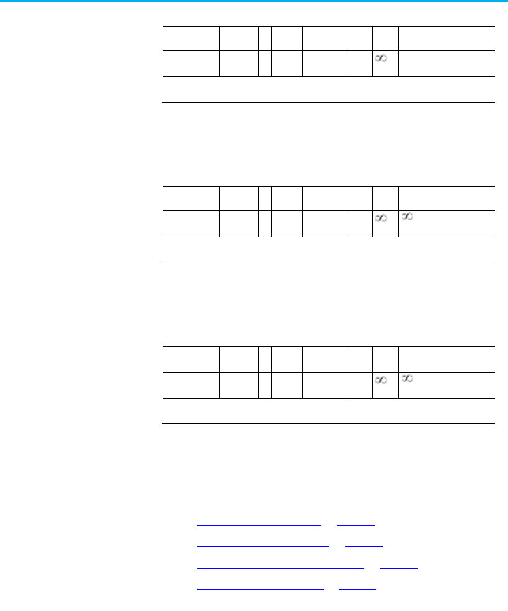
Chapter 4 CIP Axis Attributes
436 Rockwell Automation Publication MOTION-RM003O-EN-P - November 2023
Total Mass
Usage
Access
T
Data
Type
Default
Min
Max
Semantics of Values
Required - C
(Linear Motor)
Set/SSV# REAL FD 0
Mass Units
#
Indicates the attribute cannot be set while the tracking command (Tracking Command bit in CIP Axis Status is
true).
Total Mass represents the combined mass of the linear motor and load in
engineering units.
Total DC Bus Capacitance
Usage
Access
T
Data
Type
Default
Min
Max
Semantics of Values
Required - G
Set/GSV REAL Eq 25 0
F
#
Indicates the attribute cannot be set while the tracking command (Tracking Command bit in CIP Axis Status is
true).
Total DC Bus Capacitance attribute represents the combined capacitance of
the regenerative converter and external DC Bus capacitance.
External DC Bus Capacitance
Usage Access T Data
Type
Default Min Max Semantics of Values
Required - G
Set/SSV# REAL 0 0
F
#
Indicates the
attribute cannot be set while the tracking command (Tracking Command bit in CIP Axis Status is
true).
External DC Bus Capacitance represents the combined capacitance of all the
external devices that share the DC Bus output of the regenerative converter.
See also
Motor Test Result Attributes on page 440
Hookup Test Result Attributes on page 430
Hookup Test Configuration Attributes on page 429
Inertia Test Result Attributes on page 436
Auto-Tune Configuration Attributes on page 421
These are the attributes that are associated with inertia result status applied
to a Motion Control Axis.
Inertia Test Result
Attributes

Chapter 4 CIP Axis Attributes
Rockwell Automation Publication MOTION-RM003O-EN-P - November 2023 437

Chapter 4 CIP Axis Attributes
438 Rockwell Automation Publication MOTION-RM003O-EN-P - November 2023
Tune Status
Usage
Access
T
Data
Type
Default
Min
Max
Semantics of Values
Required - C Get/GSV INT - - - Enumeration
0 = Tune Successful
1 = Tune in Progress
2 = Tune Aborted
3 = Tune Time-out Fault
4 = Tune Failed - Servo Fault
5 = Axis Reached Tuning Travel
Limit
6 = Axis Polarity Set Incorrectly
7 = Tune Measurement Error
8 = Tune Configuration Error
9-127 = Reserved
128-255 = Vendor specific
128= Tune prohibited - Axis
Test Mode active
The Tune Status attribute returns status of the last run Inertia Test service
that initiates a process on the targeted drive axis. The Tune Status attribute
can, thus, be used to determine when the Inertia Test initiated operation has
successfully completed. Conditions may occur, however, that make it
impossible for the drive to properly perform the operation. When this is the
case, the Inertia Test process is automatically aborted and a failure reported
that is stored in the Tune Status output parameter. Values in the normal
vendor specific range (128-255) correspond to values defined in the
vendor-specific range in the open service on the device.
Tune Acceleration Time
Usage
Access
T
Data
Type
Default
Min
Max
Semantics of Values
Required - C Get/GSV REAL - - - Seconds
The Tune Acceleration Time attribute returns acceleration time in seconds for
the last successful Inertia Test service. This value is used to calculate the Tune
Acceleration attribute.
Tune Deceleration Time
Usage
Access
T
Data
Type
Default
Min
Max
Semantics of Values
Required - C Get/GSV REAL - - - Seconds
The Tune Deceleration Time attribute returns deceleration time in seconds of
the last successful Inertia Test service. This value is used to calculate the Tune
Deceleration attribute.

Chapter 4 CIP Axis Attributes
Rockwell Automation Publication MOTION-RM003O-EN-P - November 2023 439
Tune Acceleration
Usage
Access
T
Data
Type
Default
Min
Max
Semantics of Values
Required - C Get/GSV REAL - - - Position Units / Sec
2
The Tune Acceleration attribute returns the measured peak acceleration of the
last successful Inertia Test service. This value is used to calculate the Tune
Inertia Mass value of the axis, and is also used to determine the tuned values
for the Maximum Acceleration attribute. The Tune Acceleration value
represents the estimated acceleration at the configured torque limit of the
system.
Tune Deceleration
Usage
Access
T
Data
Type
Default
Min
Max
Semantics of Values
Required - C Get/GSV REAL - - - Position Units / Sec
2
The Tune Deceleration attribute returns the measured peak deceleration of
the last successful Inertia Test service. This value is used to calculate the Tune
Inertia Mass value of the axis, and is also used to determine the tuned values
for the Maximum Deceleration attribute. The Tune Acceleration value
represents the estimated deceleration at the configured torque limit of the
system.
Tune Inertia Mass
Usage
Access
T
Data
Type
Default
Min
Max
Semantics of Values
Required - C Set/SSV REAL 0 0
% Motor Rated / (Motor
Units/Sec
2
)
The Tune Inertia Mass value represents the estimated inertia or mass for the
axis as calculated from the measurements made during the last Motion Run
Axis Tune (MRAT) initiated tuning process. This value may also be set directly
by software tuning tools or programmatically.
Tune Friction
Usage
Access
T
Data
Type
Default
Min
Max
Semantics of Values
Required - C Set/SSV REAL 0 0
% Rated
This floating point value represents the amount of friction measured during
the last successful Inertia Test profile. This value can be used to configure the
Friction Compensation feature of the drive. This value may also be set directly
by software tuning tools or programmatically.

Chapter 4 CIP Axis Attributes
440 Rockwell Automation Publication MOTION-RM003O-EN-P - November 2023
Tune Load Offset
Usage
Access
T
Data
Type
Default
Min
Max
Semantics of Values
Required - C Set/SSV REAL 0
-
% Rated
This floating point value represents the active load offset measured during the
last successful Inertia Test profile. This value can be used to set the Torque
Offset of the drive to cancel out the active load torque/force. This value may
also be set directly by software tuning tools or programmatically.
Load Inertia Ratio
Usage
Access
T
Data
Type
Default
Min
Max
Semantics of Values
Required - C Set/SSV REAL 0 0
Load Inertia / Motor Inertia
This floating point value represents the load ratio calculated by MRAT based
on the measurements made during the last successful Inertia Test profile. The
Load Inertia Ratio attribute's value represents the ratio of the load inertia to
the motor inertia. Or in the case of a linear motor, the load mass over the
motor mass. This value can be used to set the Load Ratio attribute value as
part of an Autotune process. This value may also be set directly by software
tuning tools or programmatically.
See also
Motor Test Status Attributes on page 440
Hookup Test Status Attributes on page 430
Hookup Test Configuration Attributes on page 429
Inertia Test Configuration Attributes on page 433
Auto-Tune Configuration Attributes on page 421
These are the attributes that are associated with result status applied to a
Motion Control Axis.
Motor Test Result Attributes

Chapter 4 CIP Axis Attributes
Rockwell Automation Publication MOTION-RM003O-EN-P - November 2023 441
Motor Test Status
Usage Access T Data
Type
Default Min Max Semantics of Values
Required - D Get/GSV USINT - - - Enumeration:
0 = test process successful
1 = test in progress
2 = test process aborted
3 = test process timed-out
4 = test process faulted
5 = test reached travel limit
6 = reserved
7 = test measurement error
8 = test configuration error
9-127 = reserved
128-255 = vendor specific
128= test prohibited - axis test
mode active
The Motor Test Status attribute returns status of the last Run Motor Test
service on the targeted drive axis. The Motor Test Status attribute can be used
to determine when the motor test service has successfully completed.
Conditions may occur, however, that make it impossible for the drive to
properly perform the operation. When this is the case, the test process is
automatically terminated and a test error is reported that is stored in the
Motor Test Status output parameter. Values in the normal vendor specific
range (128-255) correspond to values defined in the vendor-specific range in
the open service on the device.
Motor Test Resistance
Usage Access T Data
Type
Default Min Max Semantics of Values
Required - D
Get/GSV
REAL
-
-
-
Ohms
This floating point value represents the stator resistance of an induction or
permanent magnet motor as measured by the Motor Test procedure.
Motor Test Inductance
Usage
Access
T
Data
Type
Default
Min
Max
Semantics of Values
Required - D
IM, SPM only
Get/GSV REAL - - - Henries
This floating point value represents the motor inductance of an induction or
permanent magnet motor as measured by the Motor Test procedure.

Chapter 4 CIP Axis Attributes
442 Rockwell Automation Publication MOTION-RM003O-EN-P - November 2023

Chapter 4 CIP Axis Attributes
Rockwell Automation Publication MOTION-RM003O-EN-P - November 2023 443
Motor Test Flux Current
Usage Access T Data
Type
Default Min Max Semantics of Values
Required - D
IM Only
Get/GSV REAL - - - Amps
This floating point value represents the motor flux current of an induction
motor as measured by the Motor Test procedure.
Motor Test Slip Speed
Usage
Access
T
Data
Type
Default
Min
Max
Semantics of Values
Required - D
IM Only
Get/GSV REAL - - - RPM: rotary motor type
m/s: linear motor type
This floating point value represents the slip speed of an induction motor as
measured by the Motor Test procedure.
Motor Test Counter EMF
Usage
Access
T
Data
Type
Default
Min
Max
Semantics of Values
Required - D
PM Only
Get/GSV REAL - - - Volts
This floating point value represents the measured Counter EMF (CEMF) of a
PM motor at Rated Speed by the Motor Test procedure.
Motor Test Lq Inductance
Usage
Access
T
Data
Type
Default
Min
Max
Semantics of Values
Required - D
IPM Only
Get/GSV REAL - - - Henries
This floating point value represents the phase-to-phase q-axis motor
inductance measured by the Motor Test procedure.
Motor Test Ld Inductance
Usage
Access
T
Data
Type
Default
Min
Max
Semantics of Values
Required - D
IPM Only
Get/GSV REAL - - - Henries

Chapter 4 CIP Axis Attributes
444 Rockwell Automation Publication MOTION-RM003O-EN-P - November 2023
This floating point value represents the phase-to-phase d-axis motor
inductance measured by the Motor Test procedure.
Motor Test Lq Flux Saturation
Usage
Access
T
Data
Type
Default
Min
Max
Semantics of Values
Required - D
IPM Only
Get/GSV REAL
[8]
- - - % Nominal Inductance
This floating point value represents the phase-to-phase q-axis stator
inductance of the motor as measured by the Motor Test procedure expressed
as a percentage of the measured Nominal Inductance, Lq, at 25%, 50%, 75%,
100%, 125%, 150%, 175% and 200% rated continuous current.
Motor Test Ld Flux Saturation
Usage
Access
T
Data
Type
Default
Min
Max
Semantics of Values
Required - D
IPM Only
Get/GSV REAL - - - % Nominal Inductance
This floating point value represents the phase-to-phase d-axis stator
inductance of the motor as measured by the Motor Test procedure expressed
as a percentage of the measured Nominal Inductance, Ld, at 100% rated
continuous current.
Motor Test Bus Overvoltage Speed
Usage
Access
T
Data
Type
Default
Min
Max
Semantics of Values
Required - D
IPM Only
Get/GSV REAL - - - RPM (rotary motor type)
m/s (linear motor type)
This floating point value represents the maximum speed of the motor without
exceeding the operational DC bus overvoltage limit, as determined by the
Motor Test procedure.
Motor Test Commutation Offset Comp
Usage
Access
T
Data
Type
Default
Min
Max
Semantics of Values
Required - D
IPM Only
Get/GSV REAL - - - Electrical Degrees
This floating point value represents the change in motor Commutation Offset
at rated continuous current as measured by the Motor Test procedure.

Chapter 4 CIP Axis Attributes
Rockwell Automation Publication MOTION-RM003O-EN-P - November 2023 445
Motor Test Flux Saturation
Usage
Access
T
Data
Type
Default
Min
Max
Semantics of Values
Required - D
SPM Only
Get/GSV
REAL[8]
- - - % Nominal Inductance
Array of measured phase-to-phase stator inductance of the motor as a
percentage of the measured Nominal Inductance, PM Motor Inductance, at
12.5%, 25%, 37.5%, 50%, 62.5%, 75%, 87.5% and 100% of the Peak Current Rating.
See also
Hookup Test Result Attributes on page 430
Inertia Test Result Attributes on page 436
Hookup Test Configuration Attributes on page 429
Inertia Test Configuration Attributes on page 433
These are the attributes that are associated with result status applied to a
Motion Control Axis.
Motor Test Travel Limit
Usage
Access
T
Data
Type
Default
Min
Max
Semantics of Values
Optional - C Set/SSV# REAL 0 0
Motor Units
The Motor Test Travel Limit attribute is used by the Dynamic Motor Test
service to limit the range of the axis travel during the test. For linear motors,
Motor Unit = Meters. For rotary motors, Motor Unit = Revs.
Motor Test Speed
Usage
Access
T
Data
Type
Default
Min
Max
Semantics of Values
Optional - D Set/SSV# REAL 0 0
Motor Units/Seconds
The Motor Test Speed attribute determines the maximum speed allowed by
the Dynamic Motor Test service during the test. For linear motors, Motor Unit
= Meters. For rotary motors, Motor Unit = Revs.
Motor Test Torque
Usage
Access
T
Data
Type
Default
Min
Max
Semantics of Values
Motor Test Configuration
Attributes

Chapter 4 CIP Axis Attributes
446 Rockwell Automation Publication MOTION-RM003O-EN-P - November 2023
Usage
Access
T
Data
Type
Default
Min
Max
Semantics of Values
Optional - D Set/SSV# REAL 100 0
% Motor Rated
The Motor Test Torque attribute determines the maximum applied torque
allowed by the Dynamic Motor Test service during the test.
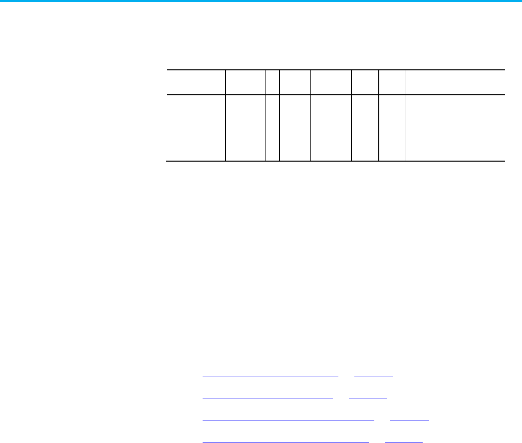
Chapter 4 CIP Axis Attributes
Rockwell Automation Publication MOTION-RM003O-EN-P - November 2023 447
Motor Test Data Valid
Usage Access T Data
Type
Default Min Max Semantics of Values
Required - D Set/GSV USINT 0 - - Enumeration:
0 = False
1 = True
2-255 = reserved
The Motor Test Data Valid attribute is set True by Studio 5000 Logix Designer
configuration software when a Motor Test is executed successfully and the
user Accepts the results of the test. This attribute is set False by Studio 5000
Logix Designer configuration software whenever the Motor Data Source
attribute is changed or whenever the values for Motor Rated Power, or Motor
Rated Voltage, or Motor Rated Current are changed.
The Motor Test Data Valid attribute is used by Studio 5000 Logix Designer
configuration software to determine if factory defaults need to be calculated
for motor model attributes.
See also
Hookup Test Result Attributes on page 430
Inertia Test Result Attributes on page 436
Hookup Test Configuration Attributes on page 429
Inertia Test Configuration Attributes on page 433
The following attribute tables contain fault and alarm related attributes
associated with a Motion Control Axis Object instance.
This attribute table has all APR (Absolute Position Recovery) faults that relate
to attributes associated with a Motion Device Axis. This includes standard
APR faults and Rockwell Automation specific APR faults. APR Faults are
conditions during device initialization when restoring the absolute position
of an axis. Unlike Initialization Faults, APR faults are recoverable. Clear APR
faults with a Fault Reset request.
Faults and Alarms
Attributes
APR Fault Attributes

Chapter 4 CIP Axis Attributes
448 Rockwell Automation Publication MOTION-RM003O-EN-P - November 2023
CIP APR Faults
Usage Access T
Data
Type
Default Min Max Semantics of Values
Optional - E Get/GSV T WORD - - - Bit map:
0 = Reserved
1 = Memory Write Error
2 = Memory Read Error
3 = Feedback Serial Number
Mismatch
4 = Buffer Allocation Fault
5 = Scaling Configuration
Changed
6 = Feedback Mode Changed
7 = Feedback Integrity Loss
8-15 = Reserved
The CIP APR Faults attribute is a bit mapped value that represents the state of
all standard APR faults. An APR fault generates when the system fails to
recover the absolute position of the axis after power cycle, reset, or
reconnection. APR faults are detected during the initial configuration or
initialization of the drive axis.
When an APR fault occurs, the actual position of the axis does not correlate to
the position of the axis prior to the power cycle, reset, or reconnect. Feedback
serial number mismatch and scaling configuration are examples of standard
APR faults. APR faults are recoverable. Clear APR faults with a Fault Reset
request.
CIP APR Faults - RA
Usage Access T
Data
Type
Default Min Max Semantics of Values
Optional - E Get/GSV T WORD - - - Bit map:
0 = Reserved
1 = Persistent Media Fault
2 = Firmware Error
3 = Feedback Battery Loss
4-15 = Reserved
The CIP APR Faults - RA attribute is a bit mapped value that represents the
state of all Rockwell Automation specific APR (Absolute Position Recovery)
faults. An APR fault generates when the system does not recover the absolute
position of the axis after power cycle, reset, or reconnection. APR faults are
detected during the initial configuration or initialization of the drive axis.
When an APR fault occurs, the actual position of the axis does not correlate to
the position of the axis before the power cycle, reset, or reconnect. These

Chapter 4 CIP Axis Attributes
Rockwell Automation Publication MOTION-RM003O-EN-P - November 2023 449
faults are specific to Rockwell Automation APR implementation. APR faults
are recoverable. Clear APR faults with a Fault Reset request.
Standard APR Faults
This table defines a list of standard faults associated with the APR Faults
attribute.
Standard APR Fault Descriptions
Bit Exception Name Description
0 -- Reserved -- This bit is not used. No fault condition is present.
1
Memory Write Error
Error occurs when saving absolute position data to nonvolatile memory.
2 Memory Read Error Error occurs when reading absolute position data from nonvolatile
memory.
3 Feedback Serial Number
Mismatch
Position Feedback Serial Number does not match the Feedback Serial
Number.
4
Buffer Allocation Fault
Occurs when there is not enough RAM memory left to save the APR data.
5 Scaling Configuration
Changed
Scaling attribute configuration for this axis changes and does not match
the saved scaling configuration.
6 Feedback Mode Changed Feedback Mode has changed and does not match the saved Feedback
Mode configuration.
7 Feedback Integrity Loss The Feedback Integrity bit of CIP Axis Status attribute has transitioned
from 1 to 0 during device operation.
8 Feedback Position Range
Changed
Absolute position feedback range has changed due to the extension of
the position feedback data type from the drive from a 32-bit DINT to a
64-bit LINT as a result of a drive firmware update, and the absolute
feedback range of the feedback device being greater than 2
32
feedback
counts.
9-15 -- Reserved --
Rockwell Automation Specific APR Faults
This table defines a list of Rockwell Automation specific faults associated with
the APR Faults-RA attribute.
Bit
Exception Name
Description
0
-- Reserved --
This bit cannot be used since the Fault Code is defined by the associated
exception bit number and Fault Code of 0 means no fault condition is present.
1 Persistent Media Fault (L6x) means that all 6 sectors reserved for APR in Persistent Memory (for
example, NAND flash) are marked as bad. This fault condition is not recoverable.
2 Firmware Error Traps firmware errors.
3 Feedback Battery Loss Battery powered Absolute Feedback device has failed to maintain absolute
position through a power cycle due to low battery level or disconnected battery
power.
4 Mover Sequencing
Without Reference
A controller detects the Mover Axis Assignment Sequence attribute is configured
to sequence movers on the track without a Reference Mover.

Chapter 4 CIP Axis Attributes
450 Rockwell Automation Publication MOTION-RM003O-EN-P - November 2023
Bit
Exception Name
Description
5 Mover Assignment
Sequence Changed
A controller detects a change to the Mover Axis Assignment sequence attribute.
6-15
-- Reserved --
The APR Fault exception names in the preceding tables have corresponding
Logix Designer APR Fault tag names. The naming conventions for the tag
names remove the spaces from the fault bit name and then append the
APRFault suffix. For example Memory Write Error becomes
MemoryWriteErrorAPRFault.
See also
Absolute Position Recovery Functionality on page 50
APR Recovery Scenarios on page 56
These configuration attributes control the action performed by the device as a
result of an exception condition. A unique exception action is defined for each
supported exception condition.
CIP Axis Exception Action
Usage Access
Data
Type
Default Min Max Semantics of Values
All Required - All Set USINT
[64]
4 (D)
2 (E)
4 (B)
4 (X)
- - Enumeration: (D)
0 = Ignore (O)
1 = Alarm (O)
2 = Fault Status Only (O)
3 = Stop Planner (O)
4 = Disable (R)
5 = Shutdown (R)
Enumeration: (E)
0 = Ignore (O)
1 = Alarm (O)
2 = Fault Status Only (R)
3 = n/a
4 = n/a
5 = Shutdown (R)
Enumeration: (XB)
0 = Ignore (O)
1 = Alarm (O)
2 = Fault Status Only (O)
3 = n/a
4 = Disable (R)
5 = Shutdown (R)
6-254 = Reserved
255 = Unsupported (O)
Axis Exception Action
Config Attrib

Chapter 4 CIP Axis Attributes
Rockwell Automation Publication MOTION-RM003O-EN-P - November 2023 451
The CIP Axis Exception Action attribute is a 64-element array of enumerated
bytes that specifies the action for the associated standard axis exception.

Chapter 4 CIP Axis Attributes
452 Rockwell Automation Publication MOTION-RM003O-EN-P - November 2023
CIP Axis Exception Action 2
Usage Access
Data
Type
Default Min Max Semantics of Values
Required - XG
Optional - NED
All
Set USINT
[64]
4 (D)
2 (E)
4 (B)
4 (X)
- - Enumeration for Drive Modes
(D)
0 = Ignore (O)
1 = Alarm (O)
2 = Fault Status Only (O)
3 = Stop Planner (O)
4 = Disable (R)
5 = Shutdown (R)
Enumeration for Feedback
Only (E)
0 = Ignore (O)
1 = Alarm (O)
2 = Fault Status Only (R)
3 = N/A
4 = N/A
5 = Shutdown (R)
Enumeration for Bus Power
Converters (B)
0 = Ignore (O)
1 = Alarm (O)
2 = Fault Status Only (O)
3 = N/A
4 = Disable (R)
5 = Shutdown (R)
6...254 = Reserved
255 = Unsupported (O)
The CIP Axis Exception Action 2 attribute is a 64-element array of enumerated
bytes that specifies the action for the associated standard axis exception.

Chapter 4 CIP Axis Attributes
Rockwell Automation Publication MOTION-RM003O-EN-P - November 2023 453
CIP Axis Exception Action - RA
Usage Access
Data
Type
Default Min Max Semantics of Values
Required - All Set USINT
[64]
4 (D)
2 (E)
4 (B)
4 (X)
- - Enumeration for Drive Modes
(D)
0 = Ignore (O)
1 = Alarm (O)
2 = Fault Status Only (O)
3 = Stop Planner (O)
4 = Disable (R)
5 = Shutdown (R)
Enumeration for Feedback
Only (E)
0 = Ignore (O)
1 = Alarm (O)
2 = Fault Status Only (R)
3 = N/A
4 = N/A
5 = Shutdown (R)
Enumeration for Bus Power
Converters (B)
0 = Ignore (O)
1 = Alarm (O)
2 = Fault Status Only (O)
3 = N/A
4 = Disable (R)
5 = Shutdown (R)
6...254 = Reserved
255 = Unsupported
The CIP Axis Exception Action attribute is a 64-element array of enumerated
bytes that specifies the action for the associated Rockwell Automation specific
axis exception.

Chapter 4 CIP Axis Attributes
454 Rockwell Automation Publication MOTION-RM003O-EN-P - November 2023
CIP Axis Exception Action 2 - RA
Usage Access
Data
Type
Default Min Max Semantics of Values
Required - G
Optional - NED
All
Set USINT
[64]
4 (D)
2 (E)
4 (B)
4 (X)
- - Enumeration for Drive Modes
(D)
0 = Ignore (O)
1 = Alarm (O)
2 = Fault Status Only (O)
3 = Stop Planner (O)
4 = Disable (R)
5 = Shutdown (R)
Enumeration for Feedback
Only (E)
0 = Ignore (O)
1 = Alarm (O)
2 = Fault Status Only (R)
3 = N/A
4 = N/A
5 = Shutdown (R)
Enumeration for Bus Power
Converters (B)
0 = Ignore (O)
1 = Alarm (O)
2 = Fault Status Only (O)
3 = N/A
4 = Disable (R)
5 = Shutdown (R)
6...254 = Reserved
255 = Unsupported
The CIP Axis Exception Action 2 attribute is a 64-element array of enumerated
bytes that specifies the action for the associated Rockwell Automation specific
axis exception.
See also
Axis Exception Action on page 454
The Axis Exception Action attributes are 64-element array of enumerated
bytes that specify the action to take by the device for the associated standard
or manufacturer specific exception, respectively. For a given exception,
certain exception actions may not be supported. Attempting to do so results in
an "Invalid Attribute Value" service error code (0x09). Each device product
must specify the available actions for each exception that is supported. If a
specific exception is not supported by the device, the only valid exception
action enumeration is 'Unsupported'. Attempting to write any other value to
the element associated with an unsupported exception results in an "Invalid
Axis Exception Action

Chapter 4 CIP Axis Attributes
Rockwell Automation Publication MOTION-RM003O-EN-P - November 2023 455
Attribute Value" service error code (0x09) that is generated while the project is
online with the controller. For drives that support Rockwell Automation
specific axis exceptions, the 64-element CIP Axis Exception Action - RA and
CIP Axis Exception Action 2 - RA arrays ares sent to the drive device.

Chapter 4 CIP Axis Attributes
456 Rockwell Automation Publication MOTION-RM003O-EN-P - November 2023
Axis Exception Action Definitions
Enum. Usage Name Description
0 Optional Ignore Ignore instructs the device to completely ignore the exception
condition. For some exceptions that are fundamental to the
operation of the axis, it may not be possible to Ignore the
condition.
1 Optional Alarm Alarm action instructs the device to set the associated bit in
the Axis Alarm word but to otherwise not impact axis behavior.
For some exceptions that are fundamental to the operation of
the device, it may not be possible to select this action or any
other action that leaves device operation unaffected.
2 Optional (XBD)
Required (E)
Fault Status Only Fault Status Only instructs the device to set the associated bit
in the Axis Faults word but to otherwise not impact axis
behavior. It is up to the controller to programmatically bring
the axis to a stop in this condition. For some exceptions that
are fundamental to the operation of the device, it may not be
possible to select this action or any other action that leaves
device operation unaffected. Converters (B) executing a Fault
Status Only exception action continue to supply DC Bus Power
and do not set the DC Bus Unload bit in Axis Status attribute
and therefore do not disable drives in the converter's Bus
Sharing Group.
3 Optional (FPV) Stop Planner Stop Planner instructs the drive device (D) to set the
associated bit in the Axis Faults word and instructs the Motion
Planner to perform a controlled stop of all planned motion at
the configured Max Decel rate. For some exceptions that are
fundamental to the operation of the device, it may not be
possible to select this action or any other action that leaves
device enabled.

Chapter 4 CIP Axis Attributes
Rockwell Automation Publication MOTION-RM003O-EN-P - November 2023 457
Enum.
Usage
Name
Description
4 Required (XBD) Disable Disable action results in the drive device (D) both setting the
associated bit in the Axis Faults word and bringing the axis to
a stop based on the factory set "best" available stopping
method. This "best" stopping method includes both the
method of decelerating the motor to a stop and the final state
of the power structure given the expected level of control still
available. The level of axis control available depends on the
specific exception condition and on the configured control
mode.
The available deceleration methods are defined by the
Stopping Action attribute. (See the
Stopping Action
section
following this table for additional information.)
If the application requires exception action that is a more
severe stopping action than the factory set "best" method, the
controller will initiate that action.
If the application requires an exception action that is less
severe than the factory set "best" method, the controller will
configure the device axis instance for a Minor Fault exception
action and handle the fault directly. This may put device and
motor components at risk and is only be allowed by the device
when there is an opportunity for the device to remain
operational. This is important in applications where the value
of the product is higher than the value of the motor or device.
When the Disable exception action is applied to a converter
device (B), stopping action is not applicable (0 = No Action).
The final states of Disable or Shutdown for the converter are
applicable, however, with Shutdown executing the configured
Shutdown Action. In the Shutdown case, the DC Bus Unload bit
of the converter's Axis Status attribute is set to generate a Bus
Sharing exception on all drives in the converter's Bus Sharing
Group.
When multiple major faults occur with different stopping
actions, the most severe of the associated stopping actions is
applied, that is, the stopping action that requires the lowest
level of control functionality. This rule also applies to the
Stopping Action associated with a Disable Request.
5 Required (All) Shutdown While the final axis state after a Major Fault is the Major
Faulted state, the Shutdown Exception Action forces the
power structure into the Shutdown state, immediately
disabling the drive's power structure. If Shutdown Action is
configured to do so, this action also drops DC Bus power to
the drive's power structure. Therefore, the Shutdown action
overrides the drive's best stopping method. An explicit
Shutdown Reset is required to restore the drive to an
operational state.
6-254 Reserved -

Chapter 4 CIP Axis Attributes
458 Rockwell Automation Publication MOTION-RM003O-EN-P - November 2023
Enum.
Usage
Name
Description
255 Unsupported The Unsupported Exception Action is the value assigned to
Exceptions that are not supported by the device. Trying to
assign an Exception Action other than Unsupported to an
exception that is not supported by the device results in an
"Invalid Attribute Value" service error code (0x09).
Stopping action
Standard stopping actions, listed in decreasing levels of deceleration control,
are as follows:
1. Ramp Decel
2. Current Limit Decel
3. Coast
In general, the "best" stopping action is the most controlled deceleration
method still available given the exception condition.
The final state of the power structure in response to the Major Fault exception
action can be any one of the following states that are listed in decreasing levels
of control functionality:
1. Hold (stopped with Holding Torque)
2. Disable (stopped with Power Structure Disabled)
3. Shutdown (stopped with Shutdown Action)
The "best" final state of the power structure is the state with the most control
functionality still available given the exception condition.
In all these final states a fault reset must be executed before the axis can be
restored to enabled operation and commanded to move.
If a Start Inhibit condition is present at the time of the exception, the best
final state for the exception action can only be Disable or Shutdown.
The specific stopping action and final state associated with a given Disable
exception action is captured in the Axis Fault Action attribute that is included
in the Fault Log record. Axis Fault Action enumerations are as follows:
Enumeration
Description
Stop Action Enumerations 0 = No Action
1 = (reserved)
2 = Ramped Stop
3 = Torque Limited Stop
4 = Coast
State Change Enumerations 0 = No Action
1 = Hold
2 = Disable
3 = Shutdown

Chapter 4 CIP Axis Attributes
Rockwell Automation Publication MOTION-RM003O-EN-P - November 2023 459
See also
Axis Exception Action Configuration Attributes on page 450
Exceptions on page 48
Exception, Fault and Alarm Attributes on page 481
Stopping and Braking Attributes on page 674
These are the configuration fault related attributes associated with a Motion
Control Axis.
Attribute Error Code
Usage Access T
Data
Type
Default Min Max Semantics of Values
Required - All Get/GSV T INT - - - Refer to CIP Error Codes
CIP Volume 1, General Status Code returned by the erred set list service to the
module.
Attribute Error ID
Usage Access T
Data
Type
Default Min Max Semantics of Values
Required - All Get/GSV T INT - - -
Attribute ID associated with non-zero Attribute Error Code.
See also
CIP Error Codes on page 459
Exception, Fault, and Alarm Attributes on page 481
Identify Motion Axis Attributes Based on Device Function Codes on
page 112
These are general CIP error codes that can be returned by the Attribute Error
Code.
CIP Error Codes
Error Code
(hex)
Error Name
Description of Error
00 Success Service was successfully performed by the object
specified.
01 Connection failure A connection related service failed along the connection
path.
Configuration Fault
Attributes
CIP Error Codes

Chapter 4 CIP Axis Attributes
460 Rockwell Automation Publication MOTION-RM003O-EN-P - November 2023
Error Code
(hex)
Error Name
Description of Error
02 Resource unavailable Resources needed for the object to perform the
requested behavior were unavailable. Further object
specific information should be supplied in the object
specific status field of the response.
03 Invalid value in object specific data
parameter of a service request
A portion of the data supplied as an object specific data
parameter of a service was invalid. The verification of
the data is specified in the object definition of the
object reporting the error.
04 IOI segment error The IOI segment identifier or the segment syntax was
not understood by the processing node. The word offset
to the first segment of the IOI that is not understood
should be supplied in the first word of the object
specific status field of the response. The offset is zero
based and calculated from the first word following the
IOI Size in the message IOI processing stops when an IOI
segment error is encountered.
05 IOI destination unknown The IOI is referencing an object class, instance or
structure element that is not known or is not contained
in the processing node. The word offset to the first
segment component that references something that is
unknown or not present in the processing node should
be supplied in the first word of the object specific
status field of the response. The offset is zero based
and calculated from the first word following the IOI Size
in the message. IOI processing stops when an IOI
destination unknown error is encountered.
06
Partial transfer
Only part of the expected data was transferred.
07
Connection lost
The messaging connectionErrpr was lost.
08 Unimplemented service The service requested was not implemented or defined
for this class or instance object.
09 Invalid attribute value The value of an attribute of the object or class is invalid.
The object specific status should report the attribute
number and the status code of the first attribute
refusing data.
0A
Attribute list error
An attribute in the Get_Attribute_List or
Set_Attribute_List response has a non–zero status.
0B Already in requested mode/state The object is already in the mode/state being requested
by the service. The object specific status should report
the object's current status.
0C Object cannot perform service in
its current mode/state
The object cannot perform the requested service in its
current mode/state. The object specific status should
report the object's current status. For example, this
error would be returned if a Transfer Service request
was sent to the NVS Object before a Update Service
request was received since the Update Service is
required before data can be sent using the Transfer
Service.
0D Object already exists The requested instance of object to be created already
exists.
0E Attribute value not settable The object attribute is not a settable attribute. The
object specific status should report the number of the
attribute refusing data.

Chapter 4 CIP Axis Attributes
Rockwell Automation Publication MOTION-RM003O-EN-P - November 2023 461
Error Code
(hex)
Error Name
Description of Error
0F Access permission does not allow
service
The access permissions do not allow the object to
perform the service. The access permissions available
to the object should be reported in the extended status.
10 Device's mode/state does not allow
object to perform service
The device containing the object does not allow the
object to perform the service in the device's current
mode/state. The object specific status should report the
device's current status. For example, a controller may
have a key switch which when set to the 'hard run' state
causes Service Requests to several different objects to
fail, for example, program edits. This error code would
then be returned.
11 Reply data too large The data to be transmitted in the response buffer is
larger than the allocated response buffer, therefore, no
data was transferred.
12 Fragmentation of a primitive value The service specified an operation that is going to
fragment a primitive data value, for example, halve a
REAL data type.
13 Not enough data The service did not supply enough data to perform the
specified operation.
14 Undefined attribute The attribute specified is not defined for the class or
object.
15 Too much data The service supplied more data than was expected
(depending on the service and the object, the service
may still be processed).
16 Object does not exist The object specified does not exist in the device.
17 Service fragmentation sequence
not currently in progress
The fragmentation sequence for this service is not
currently active for this data.
18 No stored attribute data The attribute data of this object was not saved prior to
the requested service.
19 Store operation failure The attribute data of this object was not saved due to
some failure during the attempt.
1A Bridging failure, request packet too
large for network
The service request packet was too large for
transmission on a network in the path to the
destination. The bridge device was forced to abort the
service.
1B Bridging failure, response packet
too large for network
The service response packet was too large for
transmission on a network in the path from the
destination. The bridge device was forced to abort the
service.
1C Missing attribute list entry data The service did not supply an attribute in a list of
attributes that was needed by the service to perform
the requested behavior.
1D Invalid attribute value list The service is returning the list of attributes supplied
with status information for those attributes that were
invalid.
1E
Embedded service error
An embedded service resulted in an error.
1F Connection Related Failure A service failed because of an error condition related to
the processing of a connection related service. This can
occur during connected and unconnected messaging.
The same extended status codes used for General
Status Error Code 01 are returned for this error's
extended status.

Chapter 4 CIP Axis Attributes
462 Rockwell Automation Publication MOTION-RM003O-EN-P - November 2023
Error Code
(hex)
Error Name
Description of Error
20
Invalid Parameter
Obsolete.
21 Write–once value or medium
already written
An attempt was made to write to a write-once medium
(for example, WORM drive, PROM) that has already been
written, or to modify a value that cannot be changed
once established.
22 Invalid Reply Received An invalid reply is received, for example, reply service
code does not match the request service code, or reply
message is shorter than the minimum expected reply
size. This error code can serve for other causes of
invalid replies.
23 CST not coordinated The Coordinated System Time (CST) value is not yet
within the tolerance where it can accept an update. Try
again.
24 Connection Scheduling Error Obsolete.
25 Key Failure in IOI The Key Segment which was included as the first
segment in the IOI does not match the destination
module. The object specific status will indicate which
part of the key check failed.
26 IOI Size Invalid The Size of the IOI which was sent with the Service
Request is either not large enough to allow the Request
to be routed to an object or too much routing data was
included.
27 Unexpected attribute in list An attempt was made to set an attribute that cannot be
set at this time.
28 DNet Invalid Member ID See DeviceNet specification for details:
http://www.odva.org/.
29 DNet Member not settable See DeviceNet specification for details:
http://www.odva.org/.
32D No Matching Ingress Rule This extended status code is returned when a request is
rejected due to failure to match an ingress rule.
Verify that the correct device is addressed and that the
project configuration includes devices supported by the
CIP Security Policy. If this error persists, contact the
security administrator or technical support.
32E Ingress Rule Deny This extended status code is returned when a request is
rejected due to matching an ingress rule with action
DENY.
Verify that the correct device is addressed and that the
project configuration includes devices supported by the
CIP Security Policy. If this error persists, contact the
security administrator or technical support.
32F
Ingress Rule Deny Non_Secure
This extended status code is returned when a request is
rejected due to matching an ingress rule with action
ALLOW_INGRESS_SECURE, but the request was through a
non CIP Security port.
Verify that the correct device is addressed and that the
project configuration includes devices supported by the
CIP Security Policy. If this error persists, contact the
security administrator or technical support.

Chapter 4 CIP Axis Attributes
Rockwell Automation Publication MOTION-RM003O-EN-P - November 2023 463
Error Code
(hex)
Error Name
Description of Error
330 No Matching Egress Rule This extended status code is returned when a request is
rejected due to failure to match an egress rule.
Verify that the correct device is addressed and that the
project configuration includes devices supported by the
CIP Security Policy. If this error persists, contact the
security administrator or technical support.
331 Egress Rule Deny This extended status code is returned when a request is
rejected due to matching an egress rule with action
DENY.
Verify that the correct device is addressed and that the
project configuration includes devices supported by the
CIP Security Policy. If this error persists, contact the
security administrator or technical support.
332 Egress Rule Cipher Not Allowed This extended status code is returned when a request is
rejected due to matching an egress rule with action
ALLOW, but the CIPHER_LIST does not include an allowed
cipher suite.
Verify that the correct device is addressed and that the
project configuration includes devices supported by the
CIP Security Policy. If this error persists, contact the
security administrator or technical support.
900 (D)TLS ALERT 0: Close Notify 1 One side of the (D)TLS connection has requested that
the connection be closed.
Check that the model matches the actual
communications flow.
Verify that the correct device is addressed and that the
project configuration includes devices supported by the
CIP Security Policy. If this error persists, contact the
security administrator or technical support.
901 (D)TLS ALERT 10: Unexpected
Message
Check that the model matches the actual
communications flow.
Verify that the correct device is addressed and that the
project configuration includes devices supported by the
CIP Security Policy. If this error persists, contact the
security administrator or technical support.
902 (D)TLS ALERT 20: Bad Record MAC Please contact technical support.
Verify that the correct device is addressed and that the
project configuration includes devices supported by the
CIP Security Policy. If this error persists, contact the
security administrator or technical support.
903 (D)TLS ALERT 22: Record Overflow Please contact technical support.
Verify that the correct device is addressed and that the
project configuration includes devices supported by the
CIP Security Policy. If this error persists, contact the
security administrator or technical support.
904 (D)TLS ALERT 30: Decompression
Failure
Please contact technical support.
Verify that the correct device is addressed and that the
project configuration includes devices supported by the
CIP Security Policy. If this error persists, contact the
security administrator or technical support.

Chapter 4 CIP Axis Attributes
464 Rockwell Automation Publication MOTION-RM003O-EN-P - November 2023
Error Code
(hex)
Error Name
Description of Error
905 (D)TLS ALERT 40: Handshake
Failure
Check the configuration.
Verify that the correct device is addressed and that the
project configuration includes devices supported by the
CIP Security Policy. If this error persists, contact the
security administrator or technical support.
906 (D)TLS ALERT 42: Bad Certification Please contact technical support.
Verify that the correct device is addressed and that the
project configuration includes devices supported by the
CIP Security Policy. If this error persists, contact the
security administrator or technical support.
907 (D)TLS ALERT 43: Unsupported
Certificate
Please contact technical support.
Verify that the correct device is addressed and that the
project configuration includes devices supported by the
CIP Security Policy. If this error persists, contact the
security administrator or technical support.
908 (D)TLS ALERT 44: Certificate
Revoked
Please contact technical support.
Verify that the correct device is addressed and that the
project configuration includes devices supported by the
CIP Security Policy. If this error persists, contact the
security administrator or technical support.
909 (D)TLS ALERT 45: Certificate
Expired
Please contact technical support.
Verify that the correct device is addressed and that the
project configuration includes devices supported by the
CIP Security Policy. If this error persists, contact the
security administrator or technical support.
90A (D)TLS ALERT 46: Certificate
Unknown
Check the model to see if it matches actual comms
flow. If so, contact technical support.
Verify that the correct device is addressed and that the
project configuration includes devices supported by the
CIP Security Policy. If this error persists, contact the
security administrator or technical support.
90B (D)TLS ALERT 47: Illegal Parameter Please contact technical support.
Verify that the correct device is addressed and that the
project configuration includes devices supported by the
CIP Security Policy. If this error persists, contact the
security administrator or technical support.
90C (D)TLS ALERT 48: Unknown CA Check that the model matches the actual
communication flow.
Verify that the correct device is addressed and that the
project configuration includes devices supported by the
CIP Security Policy. If this error persists, contact the
security administrator or technical support.
90D (D)TLS ALERT 49: Access Denied Check that the module matches actual communication
flow.
Verify that the correct device is addressed and that the
project configuration includes devices supported by the
CIP Security Policy. If this error persists, contact the
security administrator or technical support.

Chapter 4 CIP Axis Attributes
Rockwell Automation Publication MOTION-RM003O-EN-P - November 2023 465
Error Code
(hex)
Error Name
Description of Error
90E (D)TLS ALERT 50: Decode Error Please contact technical support.
Verify that the correct device is addressed and that the
project configuration includes devices supported by the
CIP Security Policy. If this error persists, contact the
security administrator or technical support.
90F (D)TLS ALERT 51: Decrypt Error Please contact technical support.
Verify that the correct device is addressed and that the
project configuration includes devices supported by the
CIP Security Policy. If this error persists, contact the
security administrator or technical support.
910 (D)TLS ALERT 70: Protocol Version Please contact technical support.
Verify that the correct device is addressed and that the
project configuration includes devices supported by the
CIP Security Policy. If this error persists, contact the
security administrator or technical support.
911 (D)TLS ALERT 71: Insufficient
Security
For the cipher suites configured in the module, check
that every target for an originator has a matching
cipher suite allowed.
Verify that the correct device is addressed and that the
project configuration includes devices supported by the
CIP Security Policy. If this error persists, contact the
security administrator or technical support.
912 (D)TLS ALERT 80: Internal Error Please contact technical support.
Verify that the correct device is addressed and that the
project configuration includes devices supported by the
CIP Security Policy. If this error persists, contact the
security administrator or technical support.
913 (D)TLS ALERT 86: Inappropriate
Fallback
Please contact technical support.
Verify that the correct device is addressed and that the
project configuration includes devices supported by the
CIP Security Policy. If this error persists, contact the
security administrator or technical support.
914 (D)TLS ALERT 110: Unsupported
Extension
Please contact technical support.
Verify that the correct device is addressed and that the
project configuration includes devices supported by the
CIP Security Policy. If this error persists, contact the
security administrator or technical support.
915 (D)TLS ALERT: Unknown PSK
Identity
Check that the module matches actual communication
flow. If so, contact technical support.
Verify that the correct device is addressed and that the
project configuration includes devices supported by the
CIP Security Policy. If this error persists, contact the
security administrator or technical support.
916-9FF CIP Security session error Verify that the correct device is addressed and that the
project configuration includes devices supported by the
CIP Security Policy. If this error persists, contact the
security administrator or technical support.
2A - CF Reserved for future system use This range of error codes has been reserved for future
system use.
D0 - FF Reserved for future system use This range of error codes has been reserved for use by
object and class specific services, or for development
before registration.

Chapter 4 CIP Axis Attributes
466 Rockwell Automation Publication MOTION-RM003O-EN-P - November 2023
See also
Configuration Fault Attributes on page 459
These are the exception limit related attributes associated with a Motion
Control Axis. Exception Limit attributes define the conditions under which a
corresponding exception is generated during motion axis operation that has
the potential of generating either a fault or alarm. They are typically
associated with temperature, current, and voltage conditions of the device
that are continuous in nature. Factory Limits (FL) for exceptions are usually
hard coded in the device and typically result in a major fault condition. User
Limits (UL) for exceptions are configurable and typically used to generate a
minor fault, or alarm condition. For this reason, the User Limits are generally
set inside the corresponding Factory Limits. Note that the triggering of a User
Limit exception does not preclude triggering of the corresponding Factory
Limit exception; the two exception trigger conditions are totally independent
of one another.
Rotary Motor Overspeed Factory Limit
Usage Access Data Type Default Min Max Semantics of Values
Optional - D Get REAL - - - RPM
Returns the Factory Limit for the Motor Overspeed Factory Limit exception
based on a factory set value determined by the Rotary Motor Rated Speed or
Rotary Motor Max Speed attribute values, or by operational speed limits
enforced by the drive vendor. The drive may take the minimum of any of these
values as the Factory Limit.
When PM Motor Rotary Bus Overvoltage Speed and PM Motor Rotary Max
Extended Speed attributes are supported and non-zero, the drive uses these
values to determine the Rotary Motor Overspeed Factory Limit. The PM Motor
Extended Speed Permissive value determines which limit to apply. If the PM
Motor Extended Speed Permissive is False, the Rotary Motor Overspeed
Factory Limit will be based on the PM Motor Rotary Bus Overvoltage Speed. If
the PM Motor Extended Speed Permissive is True, the Rotary Motor
Overspeed Factory Limit will be based on the PM Motor Rotary Max Extended
Speed value.
For Rockwell Automation drives, when PM Motor Extended Speed Permissive
is False, the Motor Overspeed Factory Limit = 1.25 * Bus Overvoltage Speed, or
the speed limit corresponding to the Bus Overvoltage Factory Limit,
whichever is less. When PM Motor Extended Speed Permissive is True, the
Motor Overspeed Factory Limit = 1.25 * Max Extended Speed value.
The Operational Speed Limit on all Rockwell Automation drive products is
600 Hz. The following formula is used to calculate the operational speed limit:
Exception Factory Limit
Info Attrib

Chapter 4 CIP Axis Attributes
Rockwell Automation Publication MOTION-RM003O-EN-P - November 2023 467
Operational Speed Limit (RPM) = 590 (Hz) * 120 / Rotary Motor Poles

Chapter 4 CIP Axis Attributes
468 Rockwell Automation Publication MOTION-RM003O-EN-P - November 2023
Linear Motor Overspeed Factory Limit
Usage Access Data Type Default Min Max Semantics of Values
Optional - D Get REAL - - - m/s
Returns the Factory Limit for the Motor Overspeed Factory Limit exception
based on a factory set value determined by the Linear Motor Rated Speed or
Linear Motor Max Speed attribute values, or by operational speed limits
enforced by the drive vendor. The drive may take the minimum of any of these
values as the Factory Limit.
When PM Motor Linear Bus Overvoltage Speed and PM Motor Linear Max
Extended Speed attributes are supported and non-zero, the drive uses these
values to determine the Linear Motor Overspeed Factory Limit. The PM Motor
Extended Speed Permissive value determines which limit to apply. If the PM
Motor Extended Speed Permissive is False, the Linear Motor Overspeed
Factory Limit will be based on the PM Motor Linear Bus Overvoltage Speed. If
the PM Motor Extended Speed Permissive is True, the Linear Motor
Overspeed Factory Limit will be based on the PM Motor Linear Max Extended
Speed value.
For Rockwell Automation drives, when PM Motor Extended Speed Permissive
is False, the Motor Overspeed Factory Limit = 1.25 * Bus Overvoltage Speed, or
the speed limit corresponding to the Bus Overvoltage Factory Limit,
whichever is less. When PM Motor Extended Speed Permissive is True, the
Motor Overspeed Factory Limit = 1.25 * Max Extended Speed value.
Motor Overtemperature Factory Limit
Usage Access Data Type Default Min Max Semantics of Values
Optional - D Get REAL - - -
C
The Motor Overtemperature Factory Limit attribute returns the Factory Limit
for the Motor Overtemperature FL exception based on a factory set value
related to the Motor Max Winding Temperature of the motor.
Motor Thermal Overload Factory Limit
Usage Access Data Type Default Min Max Semantics of Values
Optional - D Get REAL - - - % Motor Rated

Chapter 4 CIP Axis Attributes
Rockwell Automation Publication MOTION-RM003O-EN-P - November 2023 469
The Motor Thermal Overload Factory Limit attribute returns the Factory Limit
for the Motor Thermal Overload FL exception based on a factory set value
related to the Motor Overload Limit rating.
Inverter Overtemperature Factory Limit
Usage Access Data Type Default Min Max Semantics of Values
Optional - D Get REAL - - -
C
The Inverter Overtemperature Factory Limit returns the Factory Limit for the
Inverter Overtemperature FL exception.
Inverter Thermal Overload Factory Limit
Usage Access Data Type Default Min Max Semantics of Values
Optional - D Get REAL - - - % Inverter Rated
The Inverter Thermal Overload Factory Limit returns the Factory Limit for the
Inverter Thermal Overload FL exception based on a factory set value related to
the Inverter Overload Limit rating.
Converter Overtemperature Factory Limit
Usage Access Data Type Default Min Max Semantics of Values
Optional - BD Get REAL - - -
C
The Converter Overtemperature Factory Limit attribute returns the Factory
Limit for the Converter Overtemperature FL exception.
Converter Thermal Overload Factory Limit
Usage Access Data Type Default Min Max Semantics of Values
Optional - BD Get REAL - - - % Converter Rated
The Converter Thermal Overload Factory Limit returns the Factory Limit for
the Converter Thermal Overload FL exception.

Chapter 4 CIP Axis Attributes
470 Rockwell Automation Publication MOTION-RM003O-EN-P - November 2023
Converter Ground Current Factory Limit
Usage Access Data Type Default Min Max Semantics of Values
Optional - BD Get REAL - - - Amps
The Converter Ground Current Factory Limit attribute returns the Factory
Limit for the Converter Ground Current FL exception.
Bus Regulator Overtemperature Factory Limit
Usage Access Data Type Default Min Max Semantics of Values
Optional - BD Get REAL - - -
C
The Bus Regulator Overtemperature Factory Limit returns the Factory Limit
for the Bus Regulator Overtemperature FL exception.
Bus Regulator Thermal Overload Factory Limit
Usage Access Data Type Default Min Max Semantics of Values
Optional - BD Get REAL - - - % Regulator Rated
The Bus Regulator Thermal Overload Factory Limit attribute returns the
Factory Limit for the Bus Regulator Thermal Overload FL exception.
Bus Overvoltage Factory Limit
Usage Access Data Type Default Min Max Semantics of Values
Optional - BD Get REAL - - - Volts
The Bus Overvoltage Factory Limit returns the Factory Limit for the Bus
Overvoltage FL exception.
Bus Undervoltage Factory Limit
Usage Access Data Type Default Min Max Semantics of Values
Optional - BD Get REAL - - - Volts
Returns the Factory Limit for the Bus Undervoltage FL exception.

Chapter 4 CIP Axis Attributes
Rockwell Automation Publication MOTION-RM003O-EN-P - November 2023 471
Feedback Noise Factory Limit
Usage Access Data Type Default Min Max Semantics of Values
Optional - E Get UDINT - - - Noise Counts
Feedback Signal Loss Factory Limit
Usage Access Data Type Default Min Max Semantics of Values
Optional - E Get REAL - - - % Nominal Voltage
The Feedback Signal Loss Factory limit attribute returns the Factory Limit for
the Feedback Signal Loss FL exception.
Feedback Data Loss Factory Limit
Usage Access Data Type Default Min Max Semantics of Values
Optional - E Get UDINT - - - Consecutive Lost Data Packets
The Feedback Data Loss Factory Limit attribute returns the Factory Limit for
the Feedback Data Loss FL exception.
Control Module Overtemperature Factory Limit
Usage Access Data Type Default Min Max Semantics of Values
Optional - All Get REAL - - -
C
The Control Module Overtemperature Factory Limit returns the Factory Limit
for the Control Module Overtemperature FL exception.
Converter Pre-Charge Overload Factory Limit
Usage Access Data Type Default Min Max Semantics of Values
Optional - BD Get REAL - - - % Converter Rated
The Converter Pre-Charge Overload Factory Limit returns the Factory Limit
for the Converter Pre-Charge Overload FL exception.

Chapter 4 CIP Axis Attributes
472 Rockwell Automation Publication MOTION-RM003O-EN-P - November 2023
AC Line Overvoltage Factory Limit
Usage Access Data Type Default Min Max Semantics of Values
Optional - G Get REAL - - - % Rated
The AC Line Overvoltage Factory Limit attribute returns the factory set high
voltage limit as a percent of Converter Rated Input Voltage for the AC line
source.
AC Line Undervoltage Factory Limit
Usage Access Data Type Default Min Max Semantics of Values
Optional - G Get REAL - - - % Rated
The AC Line Undervoltage Factory Limit attribute returns the factory set low
voltage limit as a percent of Converter Rated Input Voltage for the AC line
source.
AC Line Overvoltage Factory Limit - Alternate
Usage Access Data Type Default Min Max Semantics of Values
Optional - G Get REAL - - - % Rated
The AC Line Overvoltage Factory Limit -Alternate attribute returns the
factory-set high voltage limit as a percent of Converter Rated Input Voltage
for the alternate AC line source.
AC Line Undervoltage Factory Limit - Alternate
Usage Access Data Type Default Min Max Semantics of Values
Optional - G Get REAL - - - % Rated
The AC Line Undervoltage Factory Limit - Alternate returns the factory set low
voltage limit as a percent of Converter Rated Input Voltage for the alternate
AC line source.

Chapter 4 CIP Axis Attributes
Rockwell Automation Publication MOTION-RM003O-EN-P - November 2023 473
AC Line High Freq Factory Limit
Usage Access Data Type Default Min Max Semantics of Values
Optional - G Get REAL - - - Hertz
The AC Line High Freq Factory Limit attribute returns the factory-set high
frequency limit as the difference from the nominal AC line frequency.
AC Line Low Freq Factory Limit
Usage Access Data Type Default Min Max Semantics of Values
Optional - G Get REAL - - - Hertz
The AC Line Low Freq Factory Limit attribute returns the factory set low
frequency limit as the difference from the nominal AC line frequency.
AC Line High Freq Factory Limit - Alternate
Usage Access Data Type Default Min Max Semantics of Values
Optional - G Get REAL - - - Hertz
The AC Line High Freq Factory Limit - Alternate attribute Returns the factory
set high frequency limit
as the difference from the nominal alternate AC line source frequency.
AC Line Low Freq Factory Limit - Alternate
Usage Access Data Type Default Min Max Semantics of Values
Optional - G Get REAL - - - Hertz
Returns the factory set low frequency limit as the difference from the nominal
alternate AC line source frequency.
Converter Heatsink Overtemp Factory Limit
Usage Access Data Type Default Min Max Semantics of Values
Optional - G Get REAL - - -
C

Chapter 4 CIP Axis Attributes
474 Rockwell Automation Publication MOTION-RM003O-EN-P - November 2023
The Converter Heatsink Overtemp Factory Limit returns the Factory Limit for
the regenerative converter power structure heatsink temperature. Exceeding
this value generates a Converter Overtemperature FL exception.
AC Line Overload Factory Limit
Usage Access Data Type Default Min Max Semantics of Values
Optional - G Get REAL - - - % Converter Rated
The AC Line Overload Factory Limit attribute Returns the Factory Limit for
Line 1, 2, and 3 components as a percent of their rated thermal capacity.
Exceeding this value generates a Converter Thermal Overload FL exception.
AC Line Resonance Factory Limit
Usage Access Data Type Default Min Max Semantics of Values
Optional - G Get REAL - - - % Converter Rated
The AC Line Resonance Factory Limit attribute Returns the Factory Limit for
the AC Line Resonance FL exception as a percentage of the Converter Output
Rated Current. The AC Line Resonance FL exception occurs when the current
flowing through the AC line filter in the resonant frequency band, exceeds the
factory limit for vendor specified period.
See also
Exceptions on page 48
Exception User Limit Configuration Attributes on page 474
These are the exception user limit configuration related attributes associated
with a Motion Control Axis.
Motor Phase Loss Limit
Usage
Access
Data
Type
Default
Min
Max
Semantics of Values
Optional - XD Set REAL 5 0 100 % Motor Rated
Sets the minimum motor phase current for the Motor Phase Loss exception.
The current in each motor phase must exceed this value during the motor
phase loss test or a Motor Phase Loss exception occurs. Decreasing this
Exception User Limit Config
Attrib

Chapter 4 CIP Axis Attributes
Rockwell Automation Publication MOTION-RM003O-EN-P - November 2023 475
attribute's value lowers sensitivity to phase loss conditions. A value of 0 will
effectively disable the motor phase loss test.
Motor Overspeed User Limit
Usage
Access
Data
Type
Default
Min
Max
Semantics of Values
Optional - D Set REAL FD 0
% Motor Rated
Sets the Overspeed User Limit relative to the Rotary Motor Rated Speed or
Linear Motor Rated Speed that is allowable before throwing a Motor
Overspeed UL exception.
Motor Overtemperature User Limit
Usage
Access
Data
Type
Default
Min
Max
Semantics of Values
Optional - XD Set REAL FD 0
o
C
Sets User Limit for the Motor Overtemperature UL exception.
Motor Thermal Overload User Limit
Usage
Access
Data
Type
Default
Min
Max
Semantics of Values
Optional - XD Set REAL 110 0
% Motor Rated
Sets User Limit for the Motor Thermal Overload UL exception.
Inverter Overtemperature User Limit
Usage
Access
Data
Type
Default
Min
Max
Semantics of Values
Optional - XD Set REAL
o
C
Sets User Limit for the Inverter Overtemperature UL exception.
Inverter Thermal Overload User Limit
Usage
Access
Data
Type
Default
Min
Max
Semantics of Values
Optional - XD Set REAL 110 0
% Inverter Rated
Sets User Limit for the Inverter Thermal Overload UL exception.

Chapter 4 CIP Axis Attributes
476 Rockwell Automation Publication MOTION-RM003O-EN-P - November 2023
Inverter Ground Current User Limit
Usage
Access
Data
Type
Default
Min
Max
Semantics of Values
Optional - XD Set/SSV REAL 110 0
% Factory Limit
Sets the User Limit for the Inverter Ground Current UL exception as a
percentage of the Inverter Ground Current Factory Limit.
Converter Overtemperature User Limit
Usage
Access
Data
Type
Default
Min
Max
Semantics of Values
Optional - BD Set REAL 0 0
C
Sets User Limit for the Converter Overtemperature UL exception.
Converter Thermal Overload User Limit
Usage
Access
Data
Type
Default
Min
Max
Semantics of Values
Optional - BD Set REAL 100 0
% Converter Rated
Sets User Limit for the Converter Thermal Overload UL exception.
Converter Ground Current User Limit
Usage
Access
Data
Type
Default
Min
Max
Semantics of Values
Optional - G Set/SSV REAL 100 0
% Factory Limit
Sets User Limit for the Converter Ground Current UL exceptionas a
percentage of the Converter Ground Current Factory Limit.. .
Bus Regulator Overtemperature User Limit
Usage
Access
Data
Type
Default
Min
Max
Semantics of Values
Optional - XBD Set REAL
C
Sets User Limit for the Bus Regulator Overtemperature UL exception.
Bus Regulator Thermal Overload User Limit
Usage
Access
Data
Type
Default
Min
Max
Semantics of Values
Optional - XBD Set REAL % Regulator Rated

Chapter 4 CIP Axis Attributes
Rockwell Automation Publication MOTION-RM003O-EN-P - November 2023 477
Sets User Limit for the Bus Regulator Thermal UL exception.
Bus Overvoltage User Limit
Usage Access Data
Type
Default Min Max Semantics of Values
Optional - XBD Set REAL % Nominal Bus Voltage
Sets User Limit for the Bus Overvoltage UL exception. Unlike the
corresponding Factory Limit, which is specified in Volts, the User Limit is
based on percent of Nominal Bus Voltage during operation.
Bus Undervoltage User Limit
Usage
Access
Data
Type
Default
Min
Max
Semantics of Values
Optional - XBD Set REAL % Nominal Bus Voltage
Sets User Limit for the Bus Undervoltage UL exception. Unlike the
corresponding Factory Limit, which is specified in Volts, the User Limit is
based on percent of Nominal Bus Voltage during operation.
Converter Pre-Charge Overload User Limit
Usage
Access
Data
Type
Default
Min
Max
Semantics of Values
Optional - G Set/SSV REAL 100 0
% Converter Rated
Sets User Limit for the Converter Pre-Charge Overload UL exception.
Feedback Noise User Limit
Usage
Access
Data
Type
Default
Min
Max
Semantics of Values
Optional - E Set UDINT 1 1 2
31
Noise Counts
Sets User Limit for the Feedback Noise Overload UL exception. Example of
Noise Counts would be simultaneous transitions of the A and B channel of a
quadrature encoder feedback device.
Feedback Signal Loss User Limit
Usage
Access
Data
Type
Default
Min
Max
Semantics of Values
Optional - E Set REAL 100 0
% FL Voltage Drop

Chapter 4 CIP Axis Attributes
478 Rockwell Automation Publication MOTION-RM003O-EN-P - November 2023
Sets User Limit for the Feedback Signal Loss UL exception. Feedback interface
hardware typically monitor average voltage levels on incoming signals.
Feedback Signal Loss conditions occur when the average voltage levels drop
below a percentage of voltage drop allowed by the Feedback Signal Loss
Factory Limit.
Feedback Data Loss User Limit
Usage
Access
Data
Type
Default
Min
Max
Semantics of Values
Optional - E Set UDINT 4 1 2
31
Consecutive Lost Data Packets
Sets User Limit for the Feedback Data Loss UL exception. For digital feedback
devices, feedback interface hardware monitors the integrity of data
transferred over the serial connection to the feedback device. Feedback Data
Loss conditions occur when two or more consecutive data packets are lost or
corrupted.
Control Module Overtemperature User Limit
Usage
Access
Data
Type
Default
Min
Max
Semantics of Values
Optional - All Set REAL
C
Sets User Limit for the Control Module Overtemperature UL exception.
Converter Pre-Charge Overload User Limit
Usage
Access
Data
Type
Default
Min
Max
Semantics of Values
Optional - XBD Set REAL % Rated
Sets User Limit for the Converter Pre-Charge Overload UL exception.
AC Line Overvoltage User Limit
Usage
Access
Data
Type
Default
Min
Max
Semantics of Values
Optional - G Set REAL 110 0
% Rated
Sets the high voltage limit as a percent of Converter Rated Input Voltage for
the AC line source.
AC Line Undervoltage User Limit
Usage
Access
Data
Type
Default
Min
Max
Semantics of Values

Chapter 4 CIP Axis Attributes
Rockwell Automation Publication MOTION-RM003O-EN-P - November 2023 479
Usage
Access
Data
Type
Default
Min
Max
Semantics of Values
Optional - G Set REAL 0 0 100 % Rated
Sets the low voltage limit as a percent of Converter Rated Input Voltage for
the AC line source.
AC Line Overvoltage User Limit - Alternate
Usage
Access
Data
Type
Default
Min
Max
Semantics of Values
Optional - G Set REAL 110 0
% Rated
Sets the high voltage limit as a percent of Converter Rated Input Voltage for
the alternate AC line source.
AC Line Undervoltage User Limit - Alternate
Usage
Access
Data
Type
Default
Min
Max
Semantics of Values
Optional - G Set REAL 0 0 100 % Rated
Sets the low voltage limit as a percent of Converter Rated Input Voltage for
the alternate AC line source.
AC Line High Freq User Limit
Usage
Access
Data
Type
Default
Min
Max
Semantics of Values
Optional - G Set REAL 0.4 0
Hertz
Sets the high frequency limit as the difference from the nominal AC line
frequency.
AC Line Low Freq User Limit
Usage
Access
Data
Type
Default
Min
Max
Semantics of Values
Optional - G Set REAL 0.7
-
0 Hertz
Sets the low frequency limit as the difference from the nominal AC line
frequency.
AC Line High Freq User Limit - Alternate
Usage
Access
Data
Type
Default
Min
Max
Semantics of Values

Chapter 4 CIP Axis Attributes
480 Rockwell Automation Publication MOTION-RM003O-EN-P - November 2023
Usage
Access
Data
Type
Default
Min
Max
Semantics of Values
Optional - G Set REAL 0.4 0
Hertz
Sets the high frequency limit as the difference from the nominal alternate AC
line source frequency.
AC Line Low Freq User Limit - Alternate
Usage
Access
Data
Type
Default
Min
Max
Semantics of Values
Optional - G Set REAL 0.7
-
0 Hertz
Sets the low frequency limit as the difference from the nominal alternate AC
line source frequency.
Converter Heatsink Overtemperature User Limit
Usage
Access
Data
Type
Default
Min
Max
Semantics of Values
Optional - G Set REAL 125 0
C
Sets a User Limit for the regenerative converter power structure heatsink
temperature. Exceeding this value generates a Converter Overtemperature UL
exception.
AC Line Overload User Limit
Usage
Access
Data
Type
Default
Min
Max
Semantics of Values
Optional - G Set REAL 110 0
% Converter Rated
Sets a User Limit for thermal overload of Line 1, 2, and 3 components as a
percent of their rated thermal capacity. Exceeding this value generates a
Converter Thermal Overload UL exception.
AC Line Resonance User Limit
Usage
Access
Data
Type
Default
Min
Max
Semantics of Values
Optional - G Set REAL 12 0 100 % Converter Rated
Sets the User Limit for the AC Line Resonance UL exception based on a
percentage of the Converter Output Rated Current. The AC Line Resonance
UL exception occurs when the current flowing through the AC line filter in the
resonant frequency band, exceeds the user limit for a vendor specified period.

Chapter 4 CIP Axis Attributes
Rockwell Automation Publication MOTION-RM003O-EN-P - November 2023 481
See also
Exceptions on page 48
Exception, Fault, and Alarm Attributes on page 481
Standard Exceptions on page 757
These are the exception, fault, and alarm related attributes associated with a
Motion Control Axis. Exceptions are conditions that can occur during axis
operation that have the potential of generating faults or alarms based on the
Exception Action configuration.
Axis Exceptions
Usage
Access
T
Data
Type
Default
Min
Max
Semantics of Values
Required - All Get T LWORD - - - See Semantics
The Axis Exceptions attribute is a bit map that represents the current state of
all standard exception conditions. See the Std. Exception Table bit map
definition later in this section for detail on the bit locations. Each exception
has a corresponding Axis Exception Action. Exceptions that are configured to
be Ignored are only be visible in this attribute
Axis Exceptions 2
Usage
Access
T
Data
Type
Default
Min
Max
Semantics of Values
Required - XG
Optional - NED
Get T LWORD - - - See Semantics
The Axis Exceptions 2 attribute provides a 64-bit extension to the Axis
Exceptions attribute bit map representing the current state of all standard
exception conditions. See the Std. Exception Table bit map definition later in
this section for detail on the bit locations. Each exception has a corresponding
Axis Exception Action. Exceptions that are configured to be Ignored are only
be visible in this attribute.
Axis Exceptions - Mfg
Usage
Access
T
Data
Type
Default
Min
Max
Semantics of Values
Required - All Get T LWORD - - - See Mfg. Exception Table
(Published in Product Manual)
The Axis Exceptions - Mfg attribute is a bit map that represents the current
state of all manufacturer specific exception conditions. See the Mfg.
Axis Exception, Fault, Alarm
Attrib

Chapter 4 CIP Axis Attributes
482 Rockwell Automation Publication MOTION-RM003O-EN-P - November 2023
Exception Table published in drive product manual. Each exception has a
corresponding Axis Exception Action. Exceptions that are configured to be
Ignored are only be visible in this attribute.
Axis Exceptions 2- Mfg
Usage
Access
T
Data
Type
Default
Min
Max
Semantics of Values
Required - XG
Optional - NED
Get T LWORD - - - See Mfg. Exception Table
(Published in Product Manual)
The Axis Exceptions - Mfg attribute provides a 64-bit extension to the Axis
Exceptions Mfg attribute bit map representing the current state of all
manufacturer specific exception conditions. See the Mfg. Exception Table
published in drive product manual. Each exception has a corresponding Axis
Exception Action. Exceptions that are configured to be Ignored are only be
visible in this attribute.
Axis Faults
Usage
Access
T
Data
Type
Default
Min
Max
Semantics of Values
Required - All Get T LWORD - - - See Semantics
A bit map that represents the state of all standard runtime faults. The bit map
is identical to that of the Axis Exceptions attribute. Fault bits when set are
latched until a fault reset occurs. A fault reset clears the runtime fault bits,
but the bits set again immediately if the underlying exception condition is still
present. Any exceptions whose Axis Exception Action is configured to
ignore or report as alarms do not appear in this attribute
Axis Faults 2
Usage
Access
T
Data
Type
Default
Min
Max
Semantics of Values
Required - XG
Optional - NED
Get T LWORD - - - See Semantics
This attributes provides a 64-bit extension to the CIP Axis Faults attribute bit
map representing the state of all standard runtime faults. This bit map is
identical to that of the CIP Axis Exceptions 2 attribute. Fault bits when set are
latched until a fault reset occurs. A fault reset clears the runtime fault bits,
but the bits set again immediately if the underlying exception condition is still
present.
Any exceptions whose CIP Axis Exception Action is configured to ignore or
report as alarms do not appear in this attribute.

Chapter 4 CIP Axis Attributes
Rockwell Automation Publication MOTION-RM003O-EN-P - November 2023 483
Axis Faults - Mfg
Usage
Access
T
Data
Type
Default
Min
Max
Semantics of Values
Required - All Get T LWORD - - - See Mfg. Exception Table
(Published in Product Manual)
A bit map that represents the state of all manufacturer specific runtime faults.
The bit map is identical to that of the Axis Exceptions Mfg attribute. Fault bits
when set are latched until a fault reset occurs. A fault reset clears the
runtime fault bits, but the bits set again immediately if the underlying
exception condition is still present. Any exceptions whose Axis Exception
Action is configured to ignore or report as alarms do not appear in this
attribute.
Axis Faults 2 - Mfg
Usage
Access
T
Data
Type
Default
Min
Max
Semantics of Values
Required - XG
Optional - NED
Get T LWORD - - - See Mfg. Exception Table
(Published in Product Manual)
The Axis Faults 2 - Mfg attribute provides a 64-bit extension to the Axis Faults
Mfg attribute bit map representing the state of all manufacturer specific
runtime faults. The bit map is identical to that of the Axis Exceptions Mfg
attribute. Fault bits when set are latched until a fault reset occurs. A fault
reset clears the runtime fault bits, but the bits set again immediately if the
underlying exception condition is still present. Any exceptions whose Axis
Exception Action is configured to ignore or report as alarms do not appear in
this attribute.
CIP Axis Faults - RA
Usage
Access
T
Data
Type
Default
Min
Max
Semantics of Values
Required - All Get/GSV T LWORD - - - Refer to Rockwell Automation
Specific Exceptions
A bit map that represents the state of all Rockwell Automation specific
runtime faults. Fault bits when set are latched until a fault reset occurs. A fault
reset clears the runtime fault bits, but the bits set again immediately if the
underlying exception condition is still present. Any exceptions whose CIP Axis
Exception Action is configured to ignore or report as alarms do not appear in
this attribute.

Chapter 4 CIP Axis Attributes
484 Rockwell Automation Publication MOTION-RM003O-EN-P - November 2023
CIP Axis Faults 2 - RA
Usage
Access
T
Data
Type
Default
Min
Max
Semantics of Values
Required - G
Optional - NED
Get/GSV T LWORD - - - Refer to Rockwell Automation
Specific Exceptions
This attributes provides a 64-bit extension to the CIP Axis Faults 2 attribute bit
map that represents the state of all Rockwell Automation specific runtime
faults. Fault bits when set are latched until a fault reset occurs. A fault reset
clears the runtime fault bits, but the bits set again immediately if the
underlying exception condition is still present. Any exceptions whose CIP
Axis Exception Action is configured to ignore or report as alarms do not
appear in this attribute.
Axis Alarms
Usage
Access
T
Data
Type
Default
Min
Max
Semantics of Values
Optional - All Get T LWORD - - - See Semantics
A bit map that represents the current state of all standard alarm conditions.
The bit map is identical to that of the Std. Axis Exceptions attribute. Only
exception conditions whose Axis Exception Action is configured to report as
an alarm appear in this attribute, and will not be reported in the Axis Faults
attribute. Alarm bits when set are not latched and will clear as soon as the
underlying exception condition, or multiple underlying exception
sub-conditions with different Sub Codes, is corrected.
Axis Alarms 2
Usage
Access
T
Data
Type
Default
Min
Max
Semantics of Values
Optional - All Get T LWORD - - - See Semantics
This attributes provides a 64-bit extension to the Axis Alarms attribute bit map
representing the current state of all standard alarm conditions. The bit map is
identical to that of the Axis Exceptions attribute. Only exception conditions
whose Axis Exception Action is configured to report as an alarm appear in this
attribute, and will not be reported in the Axis Faults attribute. Alarm bits
when set are not latched and will clear as soon as the underlying exception
condition, or multiple underlying exception sub-conditions with different Sub
Codes, is corrected.

Chapter 4 CIP Axis Attributes
Rockwell Automation Publication MOTION-RM003O-EN-P - November 2023 485
Axis Alarms - Mfg
Usage
Access
T
Data
Type
Default
Min
Max
Semantics of Values
Optional - All Get T LWORD - - - See Mfg. Exception Table.
(Published in Product Manual)
A bit map that represents the current state of all manufacturer specific alarm
conditions. The bit map is identical to that of the Mfg. Axis Exceptions
attribute. Only exception conditions whose Axis Exception Action is
configured to report as an alarm appear in this attribute, and will not be
reported in the Axis Faults attribute. Alarm bits when set are not latched and
will clear as soon as the underlying exception condition, or multiple exception
sub-conditions with different Sub Codes, is corrected.
Axis Alarms 2 - Mfg
Usage
Access
T
Data
Type
Default
Min
Max
Semantics of Values
Optional - All Get T LWORD - - - See Mfg. Exception Table.
(Published in Product Manual)
This attributes provides a 64-bit extension to the Axis Alarm Mfg attribute bit
map representing the current state of all manufacturer specific alarm
conditions. The bit map is identical to that of the Axis Exceptions Mfg
attribute. Only exception conditions whose Axis Exception Action is
configured to report as an alarm appear in this attribute, and will not be
reported in the Axis Faults attribute. Alarm bits when set are not latched and
will clear as soon as the underlying exception condition, or multiple
underlying exception sub-conditions with different Sub Codes, is corrected.
CIP Axis Alarms - RA
Usage
Access
T
Data
Type
Default
Min
Max
Semantics of Values
Optional- All Get/GSV T LWORD - - - Refer to Rockwell Automation
Specific Exceptions
A bit map that represents the current state of all Rockwell Automation specific
alarm conditions. Only exception conditions whose Axis Exception Action is
configured to report as an alarm appear in this attribute, and will not be
reported in the CIP Axis Faults attribute. Alarm bits when set are not latched
and will clear as soon as the underlying exception condition is corrected.

Chapter 4 CIP Axis Attributes
486 Rockwell Automation Publication MOTION-RM003O-EN-P - November 2023
CIP Axis Alarms 2 - RA
Usage
Access
T
Data
Type
Default
Min
Max
Semantics of Values
Optional- All Get/GSV T LWORD - - - Refer to Rockwell Automation
Specific Exceptions
This attributes provides a 64-bit extension to the CIP Axis Alarms 2 RA
attribute bit map that represents the current state of all Rockwell Automation
specific alarm conditions. Only exception conditions whose CIP Axis
Exception Action is configured to report as an alarm appear in this attribute,
and will not be reported in the CIP Axis Faults attribute. Alarm bits when set
are not latched and will clear as soon as the underlying exception condition is
corrected.
See also
Exceptions on page 48
Module Node Fault and Alarm Attributes on page 491
Standard Exceptions on page 757
Rockwell Automation Specific Exceptions on page 766
These are the initialization fault related attributes associated with a Motion
Control Axis. Initialization Faults are conditions that can occur during the
device initialization process that prevent normal operation of the device.
CIP Initialization Faults
Usage
Access
T
Data Type
Default
Min
Max
Semantics of Values
Required - All Get/GSV T DWORD - - - Refer to Standard Initialization
Faults
A bit map that represents the state of all standard initialization faults. These
faults prevent any motion, and do not have configurable fault actions.
Examples of initialization faults are corrupted memory data, calibration
errors, firmware startup problems, or an invalid configuration attribute value.
Initialization faults cannot be cleared with a Fault Reset service, although a
power-cycle provides a new attempt at initialization.
CIP Initialization Faults - RA
Usage
Access
T
Data Type
Default
Min
Max
Semantics of Values
Required - All Get/GSV T DWORD - - - Refer to Rockwell Automation
Specific Initialization Faults
Initialization Faults
Attributes

Chapter 4 CIP Axis Attributes
Rockwell Automation Publication MOTION-RM003O-EN-P - November 2023 487
A bit map that represents the state of all Rockwell Automation specific
initialization faults. These faults prevent any motion, and do not have
configurable fault actions. Examples of initialization faults are corrupted
memory data, calibration errors, firmware startup problems, or an invalid
configuration attribute value. Initialization faults cannot be cleared with a
Fault Reset service, although a power-cycle provides a new attempt at
initialization.
See also
Rockwell Automation Specific Initialization Faults on page 488
Standard Initialization Faults on page 487
This table defines a list of standard faults associated with the Initialization
Faults attribute.
Standard Initialization
Faults

Chapter 4 CIP Axis Attributes
488 Rockwell Automation Publication MOTION-RM003O-EN-P - November 2023
Standard Initialization Fault Descriptions
Bit Fault Description
0 Reserved This bit cannot be used since the Fault Code is defined by the
associated exception bit number and Fault Code of 0 means no fault
condition is present.
1 Boot Block Checksum Fault Checksum or CRC error for Boot Block of CIP Motion device detected
as part of Self-Test.
2 Main Block Checksum Fault Checksum or CRC error for Main Block of CIP Motion device detected
as part of Self-Test.
3 Nonvolatile Memory
Checksum Fault
Checksum or CRC error for NV Memory of CIP Motion device detected
as part of Self-Test.
4...31 Reserved
See also
Rockwell Automation Specific Initialization Faults on page 488
Initialization Faults Attributes on page 486
Standard Start Inhibits on page 697
This table defines a list of Rockwell Automation specific faults associated with
the Initialization Faults-RA attribute.
Rockwell Automation Specific Initialization Faults Bit Descriptions
Bit Fault Description
0 Reserved This bit cannot be used since the Fault Code is
defined by the associated exception bit number and
Fault Code of 0 means no fault condition is present.
1 Feedback Data Corruption Smart Encoder Data Corruption detected.
2 Feedback Data Range Data within a motor data blob is out of range.
3 Feedback Communication Startup Communications with a smart encoder could not be
established.
4 Feedback Absolute Overspeed Excessive speed was detected in the battery-backed
encoder while power was off.
5 Feedback Absolute Power Off Travel The power-off travel range of the battery-backed
encoder has been exceeded.
6 Feedback Absolute Startup Speed The absolute encoder was not able to accurately
determine the position after power-up due to speed
greater than 100 RPM.
7 Commutation Offset Uninitialized The commutation offset stored in a third-party motor
has not been initialized.
8 Reserved -
9
Reserved
-
Rockwell Automation
Specific Initialization Faults

Chapter 4 CIP Axis Attributes
Rockwell Automation Publication MOTION-RM003O-EN-P - November 2023 489
Bit
Fault
Description
10
Reserved
-
11 Reserved -
12 Invalid FPGA Image The FPGA image is incompatible with hardware
operation.
13
Invalid Board Support Package
The board support package is incompatible with
hardware operation.
14
Invalid Safety Firmware
The safety firmware is not compatible with the drive
firmware, or the main safety firmware is missing.
15 Power Board Power Board checksum error.
16 Illegal Option Card The Main Control Board has detected an illegal option
installed in the port.
17 Option Storage Checksum Option data storage checksum failed.
18 Reserved -
19 Module Voltage Mismatch Voltage rating mismatch detected on the
inter-device communications backplane.
20 Unknown Module Unknown device detected on the inter-device
communications backplane.
21 Factory Configuration Error Factory Configuration Data is missing or invalid.
22 Illegal Address Invalid Ethernet IP Address configuration or device
Node Address is out of range (>254).
23 Series Mismatch Incompatible device is detected on the inter-device
communications backplane, for example, SERCOS
AMs have been detected by the CIP IAM.
Rockwell
Automati
on24
Open Slot Open slot detected on the inter-device
communications backplane.
25 Mover Axis Assignment Track section has detected a mover to axis
assignment error.
26 Track Backplane Communication Track section has detected a problem initializing the
section addresses required to support backplane
communication around the track.
27 Unassociated Section Axis Track section has detected that section axis
instance data is missing from the connection and the
section axis has not been configured. This condition
occurs when the section axis instance has not been
associated with an axis instance of the controller, or
if the section axis has been inhibited. All mover axes
associated with this section module shall assert this
fault.
28 Track Configuration Track system has encountered a configuration error
with one of track sections that prevented the track
from performing the mover axis assignment
function. The section number of the erred track
section is passed in the Sub Code.
29-31
Reserved
-
Rockwell Automation CIP Initialization Fault Name Mapping
Bit
Object CIP Initialization Fault Name

Chapter 4 CIP Axis Attributes
490 Rockwell Automation Publication MOTION-RM003O-EN-P - November 2023
Bit
Object CIP Initialization Fault Name
0 -
1 Feedback Data Corruption Fault
2 Feedback Data Range Fault
3 Feedback Communication Startup Fault
4 Feedback Absolute Overspeed Fault
5 Feedback Absolute Power Off Travel Fault
6 Feedback Absolute Startup Speed Fault Fault
7 Commutation Offset Uninitialized
8 -
9
-
10
-
11
-
12 Invalid FPGA Image Fault
13 Invalid Board Support Package Fault
14 Invalid Safety Firmware Fault
15 Power Board Fault
16 Illegal Option Card Fault
17 Option Storage Checksum Fault
18
-
19 Module Voltage Mismatch
20 Unknown Module Fault
21 Factory Configuration Error Fault
22
Illegal Address Fault
23 Series Mismatch Fault
24 Open Slot Fault
25 Mover Axis Assignment Fault
26
Track Backplane Communication Fault
27
Unassociated Section Axis Fault
28
Track Configuration Fault
See also
Rockwell Automation Specific Exceptions on page 766
Rockwell Automation Specific CIP Axis Alarm Names on page 771
Rockwell Automation Specific CIP Axis Fault Names on page 770
Rockwell Automation Specific Start Inhibits on page 698

Chapter 4 CIP Axis Attributes
Rockwell Automation Publication MOTION-RM003O-EN-P - November 2023 491
These are the module/node fault and alarm related attributes associated with
a Motion Control Axis.
Module/Node Fault Alarm
Attributes

Chapter 4 CIP Axis Attributes
492 Rockwell Automation Publication MOTION-RM003O-EN-P - November 2023
Module Fault Bits
Usage Access T Data
Type
Default Min Max Semantics of Values
Required - All Get/GSV T DWORD - - - Bitmap
0 = Control Sync Fault
1 = Module Sync Fault
2 = Timer Event Fault
3 = Module Hard Fault
4 = Reserved
5 = Reserved
6 = Reserved
7 = Conn. Format Fault
8 = Local Mode Fault
9 = CPU Fault
10 = Clock Jitter Fault
11 = Cyclic Read Fault
12 = Cyclic Write Fault
13 = Clock Skew Fault
14 = Control Conn. Fault
15 = Reserved
16 = Module Clock Sync Fault
17 = Logic Fault
18 = Duplicate Address
19...31 = Reserved
This bit field is a roll-up of module scoped fault conditions that can include
synchronization faults detected on either side of the CIP Motion connection.
All defined Node Fault Codes are mapped into bits in this attribute. The
controller generally applies a shutdown fault action when a Module Fault
occurs and recovery generally requires module reconnection or
reconfiguration.
The following table defines a list of conditions associated with the Module
Fault Bits attributes. While the Module Fault Bits attribute is marked as
Required in the CIP Motion device implementation, support for each of the
individual fault conditions therein is left Optional. In this table the terms
motion module and motion device are used synonymously.
Bit
Module Fault
Name
Device Node Fault
Name
Description

Chapter 4 CIP Axis Attributes
Rockwell Automation Publication MOTION-RM003O-EN-P - November 2023 493
Bit
Module Fault
Name
Device Node Fault
Name
Description
0 Control Sync Fault - The Control Sync Fault bit attribute is set when the
Logix controller detects that several consecutive
connection updates from the motion module have
been missed. This condition results in the automatic
shutdown of the associated motion module. The
Logix controller is designed to "ride-through" a
maximum of four missed position updates without
issuing a fault or adversely impacting motion in
progress. Missing more than four position updates in
a row constitutes a problematic condition that
warrants shutdown of the motion module. This bit is
cleared when the connection is reestablished.
1 Module Sync Fault Control Connection
Update Fault
The Module Sync Fault bit attribute is set when the
motion module detects that several consecutive
connection updates in a row from the Logix
processor module have been missed or that an
update has been excessively late as determined by
the Controller Update Delay High Limit attribute
value. This condition results in the automatic
shutdown of the motion module. The motion module
is designed to "ride-through" a maximum of missed
or late updates without issuing a fault or adversely
impacting motion in progress. Missed or late update
that exceed the Controller Update Delay High Limit
result in the Module Sync Fault condition. This bit is
cleared when the connection is reestablished.
2 Timer Event Fault - The Timer Event Fault bit attribute is set when the
associated motion module has detected a problem
with the module's timer event functionality used to
synchronize the motion module's control loops. The
Timer Event Fault bit can only be cleared by
reconfiguration or power cycle of the motion module.
3 Module Hard Fault Hardware Fault If the Module Hardware Fault bit attribute is set it
indicates that the associated motion module has
detected a hardware problem that, in general, is
going to require replacement of the module to
correct.
4 - 6
Reserved
-
7 Conn Format Fault Data Format Error This fault bit indicates that an error has occurred in
the data format between the controller and the
device. Format errors that generate this fault may
include: an unsupported connection format, a
connection format revision mismatch, an error in the
data transmission size, incorrect number of axis
instances.
8 Local Mode Fault - The Local Mode Fault is set when the controller is
locked in Local Mode operation.
9 CPU Fault Processor Fault The Processor Fault bit indicates that the processor
associated with the device node has experienced a
fault condition or an excessive overload condition
that has tripped the associated processor watchdog
mechanism.

Chapter 4 CIP Axis Attributes
494 Rockwell Automation Publication MOTION-RM003O-EN-P - November 2023
Bit
Module Fault
Name
Device Node Fault
Name
Description
10 Clock Jitter Fault - The Clock Jitter Fault bit is set when there is
excessive clock jitter between the controller and the
motion device.
11 Cyclic Read Fault - The Cyclic Read Fault is set when the controller
detects a runtime error associated with the Cyclic
Read mechanism.
12 Cyclic Write Fault - The Cyclic Write Fault is set when the controller
detects a runtime error associated with the Cyclic
Write mechanism.
13 Clock Skew Fault Clock Skew Fault Clock Skew Fault bit indicates that the motion device
has detected significant difference between the
device's System Time and the controller's System
Time that prevented the device from switching to
synchronous operation after a time out period.
14 Control Conn Fault Control Connection
Loss Fault
The Control Connection Loss fault bit indicates that
the CIP Motion C-to-D connection from the controller
has timed out.
15
Reserved
-
16 Clock Sync Fault Clock Sync Fault The Clock Sync Fault bit indicates that the motion
device's local clock has lost synchronization with the
master clock for an extended period of time (40 to 60
seconds) during synchronous operation. This fault
condition is an indication that the local IEEE 1588
clock has lost synchronization with the master and
was not able to resynchronize within the allotted
timeout (such as 40 to 60 seconds).
17 Logic Fault Logic Fault The Logic Fault bit indicates that an auxiliary logic
component (e.g. FPGA, or ASIC) associated with the
device node has experienced fault condition or an
excessive overload condition that has tripped the
associated logic watchdog mechanism.
18 Duplicate Address
Fault
Duplicate Address
Fault
The Duplicate Address Fault bit indicates that a
motion device node has been detected on the
network that uses the same Node Address as this
device node. For Ethernet, this address would be the
IP Address of the device.
19 System
Connection Fault
System Connection
Fault
The System Connection Fault code indicates that the
device has detected that the connection to a
networked device that this device depends on has
faulted or has been closed.
20-31 Reserved - -
Module Alarm Bits
Usage
Access
T
Data
Type
Default
Min
Max
Semantics of Values

Chapter 4 CIP Axis Attributes
Rockwell Automation Publication MOTION-RM003O-EN-P - November 2023 495
Usage
Access
T
Data
Type
Default
Min
Max
Semantics of Values
Required - All Get/GSV T DWORD - - - Bitmap
0 = Control Sync Alarm
1 = Module Sync Alarm
2 = Timer Event Alarm
3 = CPU Overload Alarm
4 = Clock Jitter Alarm
5 = Out of Range Alarm
6 = Clock Skew Alarm
7 = Clock Sync Alarm
8 = Node Address Alarm
9...31 = Reserved
This bit field is a roll-up of module scoped alarm conditions that can include
synchronization alarms detected on either side of the CIP Motion connection.
All defined Node Alarm Codes are mapped into bits in this attribute.
The following table defines a list of conditions associated with the Module
Alarm Bits attributes. While the Module Alarm Bits attribute is marked as
Required in the CIP Motion device implementation, support for each of the
individual fault conditions therein is left Optional. In this table the terms
motion module and motion device are used synonymously.

Chapter 4 CIP Axis Attributes
496 Rockwell Automation Publication MOTION-RM003O-EN-P - November 2023
Bit
Alarm Name
Device Node Alarm
Name
Description
0 Control Sync Alarm - The Control Sync Alarm bit attribute is set
when the Logix controller detects that several
consecutive connection updates from the
motion module have been missed.
1 Module Sync Alarm Control Connection
Update Alarm
The Module Sync Alarm bit attribute is set when
the motion module detects that several
consecutive connection updates in a row from
the Logix processor module have been missed
or that an update has been excessively late as
determined by the Controller Update Delay Low
Limit attribute value. This bit is cleared after 10
seconds without another alarm condition.
2 Timer Event Alarm - The Timer Event Alarm bit attribute is set when
the associated motion module has detected a
problem with the module's timer event
functionality used to synchronize the motion
module's control loops. The Timer Event Alarm
bit can only be cleared by reconfiguration or
power cycle of the motion module.
3 Processor Overload Alarm Processor Overload
Alarm
The Processor Overload Alarm bit indicates
that the host processor associated with motion
device is experiencing overload conditions that
could eventually lead to a fault.
4 Clock Jitter Alarm Clock Jitter Alarm Clock Jitter Alarm bit indicates that the Sync
Variance has exceeded the Sync Threshold
while the motion device is running in Sync
Mode.
5 Out of Range Alarm - The Out of Range Alarm indicates that the
controller has detected that a Cyclic Write
attribute value or a Command Data Set value
has exceeded its allowed range.
6 Clock Skew Alarm Clock Skew Alarm Clock Skew Alarm bit indicates that the motion
device has detected significant difference
between the device's System Time and the
controller's System Time that is preventing the
device from switching to synchronous
operation.
7 Clock Sync Alarm Clock Sync Alarm The Clock Sync Alarm bit indicates that the
motion device's local clock has lost
synchronization with the master clock for a
short period of time (such as 10 to 20 seconds)
during synchronous operation. This alarm
condition can also occur when a change in the
master clock source has been detected. The
Clock Sync Alarm is an indication that the local
IEEE-1588 clock has shifted back to its start-up
mode to quickly synchronize into the master
clock.
8 Node Address Alarm Node Address Alarm The Node Address Alarm bit indicates that the
Node Address setting of the device has been
changed during motion device operation and
may no longer be valid.

Chapter 4 CIP Axis Attributes
Rockwell Automation Publication MOTION-RM003O-EN-P - November 2023 497
Bit
Alarm Name
Device Node Alarm
Name
Description
19-31
Reserved
-
See also
Exceptions on page 48
Standard Exceptions on page 757
Exception Factory Limit Info Attributes on page 466
Exception User Limit Configuration Attributes on page 474
These are the fault log attributes associated with a Motion Control Axis. CIP
Axis Fault Log
Usage
Access
T
Data
Type
Default
Min
Max
Semantics of Values
Fault Log Attributes

Chapter 4 CIP Axis Attributes
498 Rockwell Automation Publication MOTION-RM003O-EN-P - November 2023
Usage
Access
T
Data
Type
Default
Min
Max
Semantics of Values
Required - All Get Struct{
USINT,
USINT,
Struct {
USINT,
USINT,
UINT,
USINT,
USINT,
ULINT }
[25 ] }
- - - Struct {
Index;
Length;
Fault Log Struct {
Fault Type;
Fault Code;
Fault Sub Code;
Stop Action;
State Change;
Time Stamp } [ ]
}
Fault Type: Enum
0 = Faults Cleared
1 = Init Fault
2 = Init Fault - Mfg
3 = Axis Fault
4 = Axis Fault - Mfg
5 = Motion Fault
6 = Module Fault
7 = Group Fault
8 = Configuration Fault
9 = APR Fault
10 = APR Fault – Mfg
11 = Safety Fault
12 = Safety Fault - Mfg
13-127: Reserved
128-255: Vendor Specific
128 = Guard Fault
Fault Code: Enum
(Fault Type != 0)
0-255: Bit # of Fault
(Fault Type = 0)
0 = No Faults
1 = Module Reset
2 = Fault Reset
3 = Shutdown Reset
4 = Connection Reset
255 = Fault Log Reset
(Fault Type != 8)
Fault Sub Code: Enum
(Fault Type = 8)
Fault Sub Code: Attr ID
Stop Action Enum:
0 = No Action
1 = Planner Stop
2 = Ramped Stop
3 = Torque Limited Stop
4 = Immediate (Coast)
State Change Enum:
0 = No Action
1 = Hold
2 = Disable
3 Sh tdo n

Chapter 4 CIP Axis Attributes
Rockwell Automation Publication MOTION-RM003O-EN-P - November 2023 499
The CIP Axis Fault Log attribute is a structure that is used to implement a
running log of faults, complete with fault type, fault codes, and timestamps.
The elements of this structure is as follows:
The Fault Log Index points to the latest element in the Fault Log array. Each
element in the Fault Log array is called a Fault Log Record.
The Fault Log Length element indicates the number of elements in the Fault
Log array.
The Fault Type is an enumerated value indicating the type of fault condition
or fault clearing event to which the Fault Code applies.
The Fault Code indicates the specific fault condition or fault clearing event
that has occurred. For fault conditions (Fault Type != 0) the Fault Code
generally represents the bit number of the fault as defined in the associated
Axis Faults attribute. In the case of a Configuration Fault, the Fault Code
represents the Attribute Error Code. For fault clearing events (Fault Type = 0)
the Fault Code identifies the specific fault clearing event that occurred.
Possible fault clearing events are a module reset, a fault reset request, a
shutdown reset request, or a reset resulting from opening or closing a CIP
Motion connection. A Fault Code of 255 (0xFF) indicates that a Fault Log Reset
event occurred.
The Fault Sub Code is an enumeration used to provide additional detail into
the source of the fault condition. The enumeration is specific to the associated
Fault Code. For Configuration Faults, the Fault Sub Code corresponds to the
Attribute Error ID that generated the error condition.
The Stop Action element is an enumerated value that indicates what form of
stopping action the drive initiated in response to the fault condition.
The State Change element specifies what the final targeted state was for the
fault action.
The Fault Time Stamp represents the time at which the corresponding fault
was detected. The units of the time stamp are based on System Time in
microsecond units.
The CIP Axis Alarm Log attribute is a structure used to implement a running
log of alarms, complete with alarm type, alarm codes, and timestamps. The
elements of this structure is as follows:
The Alarm Log Index points to the latest element in the Alarm Log array. Each
element in the Alarm Log array is called an Alarm Log Record.
The Alarm Log Length element indicates the number of elements in the Alarm
Log array.
The Alarm Type is an enumerated value indicating the type of alarm to which
the Alarm Code applies.

Chapter 4 CIP Axis Attributes
500 Rockwell Automation Publication MOTION-RM003O-EN-P - November 2023
The Alarm Code is indicates the specific alarm that has occurred. Alarm Codes
are based on the corresponding bit number of the alarm as defined in the
associated alarm attribute.
The Alarm Code indicates the specific alarm condition or alarm clearing event
that has occurred. For alarm conditions (Alarm Type != 0) the Alarm Code
generally represents the bit number of the alarm as defined in the associated
Axis Alarm attribute. For alarm clearing events (Alarm Type = 0) the Alarm
Code identifies the specific alarm clearing event that occurred. Since alarms
are not persistent, the only alarm clearing event is an Alarm Log Reset, which
like the Fault Log Reset is given a Code of 255 (0xFF).
The Alarm Sub Code is an enumeration used to provide additional detail into
the source of the alarm condition. The enumeration is specific to the
associated Alarm Code.
The Alarm State element is an enumeration that indicates what the current
state of the associated alarm condition is. Alarm log entries are created when
an alarm condition sets (Alarm State = 1) AND when it clears (Alarm State = 0).
The Alarm Time Stamp represents the time at which the corresponding alarm
condition was detected. The units of the time stamp are based on System
Time in use units.

Chapter 4 CIP Axis Attributes
Rockwell Automation Publication MOTION-RM003O-EN-P - November 2023 501
CIP Axis Alarm Log
Usage
Access
T
Data
Type
Default
Min
Max
Semantics of Values
Optional - All Get Struct{
USINT,
USINT,
Struct {
USINT,
USINT,
UINT,
USINT,
LINT }
[25 ] }
- - - Struct {
Index;
Length;
Alarm Log Struct {
Alarm Type;
Alarm Code;
Alarm Sub Code;
Alarm State;
Time Stamp } [ ]
}
Alarm Type: Enum
0 = Alarms Cleared
1 = Start Inhibit
2 = Start Inhibit - Mfg
3 = Axis Alarm
4 = Axis Alarm - Mfg
5 = Motion Alarm
6 = Module Alarm
7 = Group Alarm
8 = Remote Get Alarm
9 = Axis Safety Alarm
10 = Axis Safety Alarm - Mfg
Alarm Code: Enum
(Alarm Type != 0)
0-255: Bit # of Alarm
(Alarm Type = 0)
255 = Alarm Log Reset
Alarm Sub Code: Enum
Alarm State: Enum
0 = Alarm Bit Off - 0
1 = Alarm Bit On - 1
The CIP Axis Alarm Log attribute is used to implement a running log of
alarms, complete with alarm type, alarm codes, and timestamps. The elements
of this structure is as follows:
The Alarm Log Index points to the latest element in the Alarm Log array. Each
element in the Alarm Log array is called an Alarm Log Record.
The Alarm Log Length element indicates the number of elements in the Alarm
Log array.
The Alarm Type is an enumerated value indicating the type of alarm to which
the Alarm Code applies.

Chapter 4 CIP Axis Attributes
502 Rockwell Automation Publication MOTION-RM003O-EN-P - November 2023
The Alarm Code is indicates the specific alarm that has occurred. Alarm Codes
are based on the corresponding bit number of the alarm as defined in the
associated alarm attribute.
The Alarm Code indicates the specific alarm condition or alarm clearing event
that has occurred. For alarm conditions (Alarm Type != 0) the Alarm Code
generally represents the bit number of the alarm as defined in the associated
Axis Alarm attribute. For alarm clearing events (Alarm Type = 0) the Alarm
Code identifies the specific alarm clearing event that occurred. Since alarms
are not persistent, the only alarm clearing event is an Alarm Log Reset, which
like the Fault Log Reset is given a Code of 255 (0xFF).
The Alarm Sub Code is an enumeration used to provide additional detail into
the source of the alarm condition. The enumeration is specific to the
associated Alarm Code.
The Alarm State element is an enumeration that indicates what the current
state of the associated alarm condition is. Alarm log entries are created when
an alarm condition sets (Alarm State = 1) AND when it clears (Alarm State = 0).
The Alarm Time Stamp represents the time at which the corresponding alarm
condition was detected. The units of the time stamp are based on System
Time in use units.
CIP Axis Fault Log Reset
Usage Access T
Data
Type
Default Min Max Semantics of Values
Required - All Set USINT - - -
Writing to the Fault Log Reset attribute clears the entire Fault Log and resets
the Fault Log Index to the 0th element, records the Fault Log Reset event and
increments the Fault Log Index to 1.
CIP Axis Alarm Log Reset
Usage Access T
Data
Type
Default Min Max Semantics of Values
Required - All Set USINT - - -
Writing to the Alarm Log Reset attribute clears the entire Alarm Log and
resets the Alarm Log Index to the 0th element, records the Alarm Log Reset
event and increments the Alarm Log Index to 1.
CIP Axis Fault Log Count
Usage Access T
Data
Type
Default Min Max Semantics of Values
Required - All Get USINT - - -

Chapter 4 CIP Axis Attributes
Rockwell Automation Publication MOTION-RM003O-EN-P - November 2023 503
This number is a running count of records added to the fault log. This number
is initialized to 0 at power-up, or by a controller reset, and is incremented
with every record added to the CIP Axis Fault Log. This attribute may be used
by software to determine if there are new fault log records to upload.
CIP Axis Alarm Log Count
Usage Access T
Data
Type
Default Min Max Semantics of Values
Required - All Get USINT - - -
This number is a running count of records added to the alarm log. This
number is initialized to 0 at power-up or by a controller reset, and is
incremented with every record added to the CIP Axis Alarm Log. This
attribute may be used by software to determine if there are new alarm log
records to upload.
CIP Axis Alarm Source
Usage Access T
Data
Type
Default Min Max Semantics of Values
Optional - All Get USINT
[128]
- - -
# of Active Alarm Sub Codes
The CIP Axis Alarm Source attribute is a 128-element array of 8-bit unsigned
integers representing the number of active Sub Code source conditions for
each possible CIP Axis Alarm. Multiple source conditions can be active at any
given time. These source conditions are identified by their Alarm Sub Code.
This attribute is used by the controller to determine when to set, and when to
clear, the associated CIP Axis Alarms bit.
The array index into this attribute corresponds to the CIP Axis Alarms bit
number (the Axis Alarm Code). The number of Active Alarm Sub Codes is
incremented whenever new active alarm source condition is posted to the
Alarm Log for a given alarm. The number of Active Alarm Sub Codes is
decremented whenever an active alarm source condition is cleared in the
Alarm Log for a given alarm.
After processing the Alarm Sub Code and incrementing or decrementing the
associated Active Alarm Sub Code counter, the state of the associated CIP Axis
Alarms bit is determined by the Active Alarm Sub Code counter value. If the
counter value is greater than 0, the CIP Axis Alarms bit shall be set. If the
counter value is 0, the associated CIP Axis Alarms bit shall be cleared.
Axis Alarm sources are identified by their associated Axis Alarm Sub Code
from the CIP Motion device. Multiple alarm sources for a given alarm could,
for example, come from different feedback channels, or from different power
structure instances.

Chapter 4 CIP Axis Attributes
504 Rockwell Automation Publication MOTION-RM003O-EN-P - November 2023
CIP Axis Alarm Source - RA
Usage Access T
Data
Type
Default Min Max Semantics of Values
Optional - All Get USINT
[128]
- - -
# of Active Alarm Sub Codes
The CIP Axis Alarm Source RA attribute is a 128-element array of 8-bit
unsigned integers representing the number of active Sub Code source
conditions for each possible RA specific CIP Axis Alarm. Multiple source
conditions can be active at any given time. These source conditions are
identified by their Alarm Sub Code. This attribute is used by the controller to
determine when to set, and when to clear, the associated CIP Axis Alarms RA
bit.
The array index into this attribute corresponds to the CIP Axis Alarms RA bit
number (the Axis Alarm Code). The number of Active Alarm Sub Codes is
incremented whenever new active alarm source condition is posted to the
Alarm Log for a given alarm. The number of Active Alarm Sub Codes is
decremented whenever an active alarm source condition is cleared in the
Alarm Log for a given alarm.
After processing the Alarm Sub Code and incrementing or decrementing the
associated Active Alarm Sub Code counter, the state of the associated CIP Axis
Alarms RA bit is determined by the Active Alarm Sub Code counter value. If
the counter value is greater than 0, the CIP Axis Alarms RA bit shall be set. If
the counter value is 0, the associated CIP Axis Alarms RA bit shall be cleared.
Axis Alarm sources are identified by their associated Axis Alarm Sub Code
from the CIP Motion device. Multiple alarm sources for a given alarm could,
for example, come from different feedback channels, or from different power
structure instances.
CIP Start Inhibit Source
Usage Access T
Data
Type
Default Min Max Semantics of Values
Optional - All Get USINT
[16]
- - -
# of Active Alarm Sub Codes
The CIP Start Inhibit Source attribute is a 16-element array of 8-bit unsigned
integers representing the number of active Sub Code source conditions for
each possible CIP Start Inhibit. Multiple source conditions can be active at any
given time. These source conditions are identified by their Alarm Sub Code.
This attribute is used by the controller to determine when to set, and when to
clear, the associated CIP Start Inhibits bit.
The array index into this attribute corresponds to the CIP Start Inhibits bit
number (the Axis Alarm Code). The number of Active Alarm Sub Codes is
incremented whenever new active alarm source condition is posted to the
Alarm Log for a given alarm. The number of Active Alarm Sub Codes is

Chapter 4 CIP Axis Attributes
Rockwell Automation Publication MOTION-RM003O-EN-P - November 2023 505
decremented whenever an active alarm source condition is cleared in the
Alarm Log for a given alarm.
After processing the Alarm Sub Code and incrementing or decrementing the
associated Active Alarm Sub Code counter, the state of the associated CIP
Start Inhibits bit is determined by the Active Alarm Sub Code counter value. If
the counter value is greater than 0, the CIP Start Inhibits bit shall be set. If the
counter value is 0, the associated CIP Start Inhibits bit shall be cleared.
Start Inhibit sources are identified by their associated Axis Alarm Sub Code
from the CIP Motion device. Multiple start inhibit sources for a given start
inhibit could, for example, come from different feedback channels, or from
different power structure instances.
CIP Start Inhibit Source - RA
Usage Access T
Data
Type
Default Min Max Semantics of Values
Optional - All Get USINT
[16]
- - -
# of Active Alarm Sub Codes
The CIP Start Inhibit Source attribute is a 16-element array of 8-bit unsigned
integers representing the number of active Sub Code source conditions for
each possible RA specific CIP Start Inhibit. Multiple source conditions can be
active at any given time. These source conditions are identified by their Alarm
Sub Code. This attribute is used by the controller to determine when to set,
and when to clear, the associated CIP Start Inhibits RA bit.
The array index into this attribute corresponds to the CIP Start Inhibits RA bit
number (the Axis Alarm Code). The number of Active Alarm Sub Codes is
incremented whenever new active alarm source condition is posted to the
Alarm Log for a given alarm. The number of Active Alarm Sub Codes is
decremented whenever an active alarm source condition is cleared in the
Alarm Log for a given alarm.
After processing the Alarm Sub Code and incrementing or decrementing the
associated Active Alarm Sub Code counter, the state of the associated CIP
Start Inhibits RA bit is determined by the Active Alarm Sub Code counter
value. If the counter value is greater than 0, the CIP Start Inhibits RA bit shall
be set. If the counter value is 0, the associated CIP Start Inhibits RA bit shall
be cleared.
Start Inhibit sources are identified by their associated Axis Alarm Sub Code
from the CIP Motion device. Multiple start inhibit sources for a given start
inhibit could, for example, come from different feedback channels, or from
different power structure instances.

Chapter 4 CIP Axis Attributes
506 Rockwell Automation Publication MOTION-RM003O-EN-P - November 2023
See also
Initialization Faults Attributes on page 486
The following position feedback related attribute tables associated with a
Motion Control Axis apply to various feedback device and feedback interface
technologies.
Feedback interface technologies include:
• Digital AqB (digital A quad B signals)
• Sine/Cosine (analog A quad B signals)
• Digital Parallel (parallel digital bit interface)
• SSI (Synchronous Serial Interface)
• LDT (Linear Displacement Transducer)
• Resolver
Other modern feedback interfaces supported are: Hiperface and Hiperface
DSL (by Stegmann) and EnDat 2.1 and EnDat 2.2 (by Heidenhain). The Usage
column for a feedback attribute is based on the context of the Feedback Type.
Abbreviations for the various Feedback Types are defined in this table:
Feedback Type abbreviations
Abbreviation
Feedback Type
TT Digital AqB
TP Digital Parallel
SC
Sine/Cosine
HI Hiperface
HD Hiperface DSL
ED EnDat 2.1 and 2.2
INT
Integrated
RS
Resolver
SS
SSI
LT
LDT - Linear Displacement Transducer
TG
Tamagawa
NK
Nikon
SL Stahl SSI
TM Track Mover
TS
Track Section
Tamagawa (TG), Nikon (NK), and Stahl SSI (SL) are serial interface protocols
for encoders. Track Section (TS) and Track Mover (TM) are applicable to
track-based systems. The position feedback characteristics of the track split
between track sections and track movers. Section electronics determine
feedback resolution and the feedback range for the Track Section component
of the feedback electronics.
This section defines the minimal set of required attributes to support CIP
Motion device interchangeability. This guarantees that there is sufficient
Feedback Attributes
Feedback Interface Types

Chapter 4 CIP Axis Attributes
Rockwell Automation Publication MOTION-RM003O-EN-P - November 2023 507
parametric data provided by the controller for any CIP Motion compliant
drive to effectively interface to a wide range of feedback device types.
Multiple feedback device interfaces are currently defined by the Motion
Control Axis per axis to serve specific control or master feedback functions.
These feedback devices are accessed using their assigned logical channels, for
example, Feedback 1 and Feedback 2. Each logical feedback channel is mapped
to a physical feedback interface port of the device, for example Port 1, and Port
2.
Logical Feedback Channel Control Functions
Logical Feedback
Channel
Motion Control Function
Master Feedback Function
Feedback 1
Motor Feedback and Commutation
Master Feedback 1
Feedback 2 Load-side Feedback Master Feedback 2
Feedback 3 Vendor Specific Vendor Specific
Feedback 4 Vendor Specific Vendor Specific
Feedback 3 Redundant Motor Feedback Redundant Master Feedback 1
Feedback 4 Redundant Load-side Feedback Redundant Master Feedback 2
When the Control Mode is set to something other than No Control, Feedback 1
is associated with the motor mounted feedback device while Feedback 2 is
associated with the load-side or machine mounted feedback device. Feedback
1 is always required for PM Motor commutation.
When Control Mode is set to No Control for a Motion Control Axis, different
logical feedback channels can be used as the master feedback source, for
example, Feedback 1 and Feedback 2. Generally, Feedback 1 is used.
For Rockwell Automation devices Feedback 3 is used to provide a redundant
logical feedback channel for Feedback 1 while Feedback 4 is used to provide a
redundant logical channel for Feedback 2.
To minimize the length of the feedback attribute tables below, the letter n in
the generic Feedback n attribute name is used to specify the associated
feedback channel number. Valid channel numbers for open standard feedback
attributes of the Motion Control Axis are 1, 2, 3 and 4.
Attribute IDs are assigned based on the channel number. Support for
feedback interface channels 1, 2, 3 and 4 are optional in the device
implementation. If no feedback interface channel is present in the device the
associated set of feedback channel attributes are not applicable.
However, if hardware support for any of these feedback channels is available
in a given device, these attributes are clearly applicable in the implementation
and will follow the Usage rules. A Usage rule of 'Req - E' or 'Opt - E' indicates
that the attribute is generally applicable to all Device Control Codes where the
feedback channel itself is applicable, hence the 'E' for Encoder.

Chapter 4 CIP Axis Attributes
508 Rockwell Automation Publication MOTION-RM003O-EN-P - November 2023
If a specific logical feedback channel, feedback n, is not applicable based on
the current feedback configuration, then attributes for feedback n are not
applicable; no feedback configuration attributes for that channel are set by
configuration software, nor are any such attributes sent to the drive device.
This table outlines these rules:
Feedback Configuration
Feedback 1
Feedback 2
No Feedback No No
Master Feedback Yes No
Motor Feedback Yes No
Load Feedback Yes
(1)
Yes
Dual Feedback Yes Yes
Dual Integrator Feedback
Yes
Yes
(1)
Feedback 1 channel is needed for commutation of PM Motors.
See also
General Feedback Info Attributes on page 524
General Feedback Signal Attributes on page 524
Feedback Configuration Attributes on page 508
The Feedback Configuration attributes determines how the various available
feedback channels are used to implement the selected Control Mode.
Feedback Configuration
Usage
Access
Data
Type
Default
Min
Max
Semantics of Values
Required - All Set/GSV USINT 0 (B, F)
1 (E)
2 (XC)
0 15 Enumeration:
0 = No Feedback
1 = Master Feedback
2 = Motor Feedback
3 = Load Feedback
4 = Dual Feedback
5-7 = Reserved
8 = Dual Int Feedback
8-15 = Reserved
Bits 4-7:Reserved
When configured, this attribute also sets the initial value for Feedback Mode.
This attribute contains a 4-bit enumerated value that determines how the
various logical feedback channels are used to implement the selected Control
Mode for this axis instance.
Feedback Configuration enumerations provide support for multi-feedback
device control functionality for the various active device Control Modes, for
example, where the device is actively controlling the motor based on feedback.
In these active device Control Modes it is assumed that logical channel,
Feedback Configuration
Attributes

Chapter 4 CIP Axis Attributes
Rockwell Automation Publication MOTION-RM003O-EN-P - November 2023 509
Feedback 1, is attached directly to the motor while Feedback 2 is attached to
the load side of the mechanical transmission. Commutation signals for a PM
motor are always derived from the Feedback 1, except in the case of an active
redundant feedback source.
This table describes the Feedback Configuration enumerations:
Bit
Usage
Name
Description
0 R/S No Feedback No Feedback is selected when sensorless open loop or closed
loop control is desired. When performing open loop control, no
feedback signal is required. In closed loop control, the
required feedback signal is estimated by a sensorless control
algorithm based on motor phase voltage and current signals.
1 R/N Master Feedback Master Feedback assigns an uncommitted feedback channel
to this device axis instance to serve as a master feedback
source when the device is configured for No Control mode
2 R/C Motor Feedback When Motor Feedback is selected, then commutation,
acceleration, velocity, and position feedback signals are all
derived from motor mounted Feedback 1
3 O/C Load Feedback When Load Feedback is selected, then motor-mounted
Feedback 1 is only used for PM motor commutation while
load-side Feedback 2 is used for position, velocity, and
acceleration.
4 O/P Dual Feedback When Dual Feedback is selected, then motor mounted
Feedback 1 is used for commutation, acceleration, and
velocity, and load-side Feedback 2 is used strictly for position.
5-7
-
Reserved
-
8 O/P Dual Integrator
Feedback
Dual Integral Feedback means that motor-mounted Feedback
1 is used for commutation, acceleration, velocity, and position
proportional control, and load-side Feedback 2 is used only
for integral position control. This optimizes the stiffness of
the control loop at low frequency.
9-15 - Reserved -
Feedback Mode
Usage
Access
Data
Type
Default
Min
Max
Semantics of Values

Chapter 4 CIP Axis Attributes
510 Rockwell Automation Publication MOTION-RM003O-EN-P - November 2023
Usage
Access
Data
Type
Default
Min
Max
Semantics of Values
Required - XED
(Derived from
Feedback
Configuration)
Get/SSV USINT 0 0 15 Bits 0-3: Feedback Mode
Enumeration
0 = No Feedback
1 = Master Feedback
2 = Motor Feedback
3 = Load Feedback
4 = Dual Feedback
5-7 = Reserved
8-15 = Vendor Specific
8 = Dual Int Feedback
Bits 4-5: Feedback Data Type
Enumeration
0 = DINT (32-bit integer)
1 = LINT (64-bit integer)
2-3 = Reserved
Bits 6-7 = Reserved
*
Indicates the attribute cannot be set while the drive power structure is enabled (Power Structure Enable bit in
CIP Axis Status is true).
The Feedback Mode attribute determines how the various available feedback
channels are used to implement the selected Control Mode. This attribute is
transferred to the device as part of the Cyclic data block. Currently bits 0-3 are
used to enumerate the Feedback Mode configuration. Bits 4-5 are used to
select the position feedback data type. Bit 5-7 are reserved for future use.
This attribute contains the 4-bit enumerated Feedback Mode field derived
from the Feedback Configuration attribute that determines how the various
logical feedback channels are used to implement the selected Control Mode
for this axis instance. The attribute also contains a 2-bit enumerated field,
Feedback Data Type, which determines the Actual Position data type that is to
be included in the Device-to-Controller connection Cyclic Data Block, with
options for 32-bit or 64-bit signed integer representations. The Feedback Data
Type field value is determined by the Extended Position Feedback bit (bit 20)
of the Axis Features attribute, and is not user configurable in this
implementation.
Feedback Mode field enumerations provide support for multi-feedback device
control functionality for the various active device Control Modes, for example,
where the device is actively controlling the motor based on feedback. In these
active device Control Modes it is assumed that logical channel, Feedback 1, is
attached directly to the motor while Feedback 2 is attached to the load side of
the mechanical transmission. Commutation signals for a PM motor are
always derived from the Feedback 1, except in the case of an active redundant
feedback source.
Bit
Usage
Name
Description

Chapter 4 CIP Axis Attributes
Rockwell Automation Publication MOTION-RM003O-EN-P - November 2023 511
Bit
Usage
Name
Description
0 R/!E No Feedback No Feedback is selected when sensorless/encoderless open loop
or closed loop control is desired. When performing open loop
control, no feedback signal is required. In closed loop control, the
required feedback signal is estimated by a sensorless control
algorithm based on motor phase voltage and current signals
1 R/E Master Feedback Master Feedback assigns an uncommitted feedback channel to
this device axis instance to serve as a master feedback source
when the device is configured for No Control mode.
2 R/XC Motor Feedback When Motor Feedback is selected, commutation, acceleration,
velocity, and position feedback signals are all derived from motor
mounted Feedback 1.
3 O/C Load Feedback When Load Feedback is selected, then motor-mounted Feedback 1
is only used for PM motor commutation while load-side Feedback 2
is used for position, velocity, and acceleration.
4 O/P Dual Feedback When Dual Feedback is selected, then motor mounted Feedback 1
is used for commutation, acceleration, and velocity, and load-side
Feedback 2 is used strictly for position.
5-7
-
Reserved
-
8 O/P Dual Integrator
Feedback
Dual Integral Feedback means that motor-mounted Feedback 1 is
used for commutation, acceleration, velocity, and position
proportional control, and load-side Feedback 2 is used only for
integral position control. This optimizes the stiffness of the control
loop at low frequency.
9-15
-
Reserved
-
When modified programmatically, using SSV, only the Feedback Mode field
value can be changed, all other bits are ignored by the instruction.
Furthermore, the Feedback Mode field value, cannot be set to an enumeration
that the Feedback Configuration cannot support. Attempting to do so results
in the SSV instruction generating a Minor Fault. For example if the Feedback
Configuration is set for Motor Feedback, the Feedback Mode cannot be
changed to Load Feedback since that feedback channel has not been
configured.
Feedback Mode SSV Promotion Rules
The following table describes valid Feedback Modes.
Feedback Configuration
Valid Feedback Modes
No Feedback
No Feedback
Master Feedback Master Feedback
Motor Feedback Motor Feedback
No Feedback
Load Feedback Load Feedback
Dual Feedback
Motor Feedback
No Feedback

Chapter 4 CIP Axis Attributes
512 Rockwell Automation Publication MOTION-RM003O-EN-P - November 2023
Feedback Configuration
Valid Feedback Modes
Dual Feedback Dual Feedback
Load Feedback
Motor Feedback
No Feedback
Feedback Master Select
Usage Access Data
Type
Default Min Max Semantics of Values
Optional - NE Set/GSV USINT 1
- - Enumeration:
0 = (Reserved)
1 = Feedback 1
2 = Feedback 2
2-255 = (reserved)
The Feedback Master Select attribute determines what Logical channel is
assigned to this axis instance when the Feedback Mode is set to Master
Feedback. Default is Feedback 1.
Feedback Unit Ratio
Usage
Access
Data
Type
Default
Min
Max
Semantics of Values
Optional -E PV
only
Set/GSV REAL 1
Eq 6
- - Feedback 1 Units per Feedback 2
Units
The Feedback Unit Ratio attribute is the number of Feedback 1 Units per
Feedback 2 Units. This value is used to convert from feedback 2 units or
counts to feedback 1 units or counts when configured for dual loop or load
side feedback operation. The Feedback Ratio block that applies the Feedback
Unit Ratio scaling factor appears in the Position Loop and Torque Reference
block diagrams.
Feedback n Resolution Unit
Usage
Access
Data Type
Default
Min
Max
Semantics of Values
Optional - E Set USINT 0
CU
- - Enumeration
0 = Cycles/Unit (R)
1 = Units/Cycle (O) (linear only)
2 = Bits/Unit (O) (rotary only)
3-127 = (reserved)
128-255 = (vendor specific)
The Feedback n Resolution Unit attribute is the unit of measure for feedback
resolution used by Feedback n Cycle Resolution attribute. Default selection is
Cycles/Unit where resolution is expressed in feedback cycles per revolution
for rotary feedback devices or per meter for linear feedback devices. If
Units/Cycle is selected then Feedback n Cycle Resolution shall be expressed in

Chapter 4 CIP Axis Attributes
Rockwell Automation Publication MOTION-RM003O-EN-P - November 2023 513
Nanometers/Cycle for linear feedback devices. This selection is not applicable
to rotary devices. If Bits/Unit is selected then Feedback n Cycle Resolution is
expressed as 2n Cycles per revolution of a rotary feedback device, where n is
the number of bits in the binary position representation of the device. This
selection is not applicable for linear devices.
Feedback n Unit
Usage
Access
Data
Type
Default
Min
Max
Semantics of Values
Required - E Set USINT 0
DB
- - Enumeration
0 = Rev
1 = Meter
2-127 = Reserved
128-255 = Vendor Specific
The Feedback n Unit attribute is a unit of measure for the designated
feedback device. The Feedback Unit for Feedback 1 and any redundant
feedback device for Feedback 1 shall be the same as the configured Motor
Unit.
If the Motor Unit is set to Rev, Feedback 1 Unit shall be set to Rev. If Motor
Unit is set to Meter, Feedback 1 Unit shall be set to Meter. Feedback devices
with a Feedback Unit of Rev are considered “rotary” devices, while Feedback
devices with a Feedback Unit of Meter are considered “linear” devices.
Feedback n Port Select
Usage
Access
Data
Type
Default
Min
Max
Semantics of Values
Optional - E Set USINT 0
FC
- - Enumeration
0 = Unused (R)
1-255 = Feedback Port ID (0)
The Feedback n Port Select attribute maps the logical Feedback Channel “n” to
a physical Feedback Port ID. A Feedback Port ID is assigned to each feedback
interface port of the device by the drive vendor. If the drive does not support
this attribute, the drive vendor shall hard-code the feedback port mapping to
the logical Feedback Channels for each axis instance. Supporting the
Feedback n Port Select attribute allows flexibility to map the logical Feedback
Channels to different Feedback Ports.
Default Feedback n Port Select = 0. A value of 0 indicates that Feedback n
Channel is unmapped, hence unused.

Chapter 4 CIP Axis Attributes
514 Rockwell Automation Publication MOTION-RM003O-EN-P - November 2023
Feedback n Type
Usage Access Data
Type
Default Min Max Semantics of Values
Required - E Set/GSV USINT 0
DB
- - Enumeration
0 = Not Specified (R)
1 = Digital AqB (O)
2 = Digital AqB with UVW (O)
3 = Digital Parallel (O)
4 = Sine/Cosine (O)
5 = Sine/Cosine with UVW (O)
6 = Hiperface (O)
7 = EnDat Sine/Cosine (O)
8 = EnDat Digital (O)
9 = Resolver (O)
10 = SSI Digital (O)
11 = LDT (O)
12 = Hiperface DSL (O)
13 = BiSS Digital (O)
14 = Integrated (O)
15 = SSI Sine/Cosine (O)
16 = SSI AqB (O)
17 = BiSS Sine/Cosine (O)
18-127 = Reserved
128-255 = Vendor Specific
128 = Tamagawa Serial (O)
129 = Stahl SSI (O)
130 = Track Section (O)
131 = Track Mover (O)
132 = Nikon Serial(O)
The Feedback n Type attribute Identifies the type of feedback interface of the
associated Feedback device channel. Drive support for any individual
feedback type is left to the discretion of the device manufacturer. However, if
a specific feedback type is supported, attributes associated with that type are
generally required in the implementation.
The “Integrated” Feedback Type is specified for CIP Motion compliant devices
with an integral feedback transducer function, for example, a CIP Motion
encoder.
In the case of a motor mounted feedback device, if Motor Data Source is
Motor NV or Drive NV, the Feedback 1 Type might not be known to the
controller but is known by the drive, so the drive can operate in this case
without specifying the Feedback 1 Type.
If the optional Commutation Startup Method attribute is not supported by the
device, or the Commutation Startup Method is set to From Feedback Type, the
Feedback 1 Type can be used to implicitly specify the commutation startup

Chapter 4 CIP Axis Attributes
Rockwell Automation Publication MOTION-RM003O-EN-P - November 2023 515
method. For example, by selecting the Feedback 1 Type with or without UVW
commutation signals the device applies the UVW commutation startup
method or the Self-Sense startup method, respectively. In this case, UVW
commutation signals can be derived from UVW tracks integral to the
feedback device or via separate Hall sensors in the motor. All other Feedback 1
Type selections would apply the Digital commutation startup method.
In the case of a motor mounted feedback device, if the Motor Data Source is
Controller NV, an unspecified Feedback 1 Type, when received by the drive
device during configuration, indicates that the motor feedback configuration
has not been defined and therefore results in a General Status error of Invalid
Attribute Value.
Feedback n Polarity
Usage
Access
Data
Type
Default
Min
Max
Semantics of Values
Optional - E Set USINT 0 - - Enumeration
0 = Normal
1 = Inverted
2-225 = Reserved
The Feedback n Polarity attribute is an enumerated value used to establish the
direction of change in the feedback counter in response to positive motion of
the associated feedback device. Normal polarity is defined as that which
results in increasing feedback counts when the feedback device is hooked up
and moved in the positive direction according to the devices published
specifications.
Inverted polarity internally switches the polarity of the feedback accumulator
so that the feedback counts decrease when the feedback device moves in the
positive direction. This attribute can be used to make the direction of travel
agree with the user's definition of positive travel and can be used in
conjunction with the Motor Polarity bit to provide negative feedback, when
this feedback channel is used for closed loop control.
Feedback n Startup Method
Usage
Access
Data
Type
Default
Min
Max
Semantics of Values
Required - E
N/A for X
Set USINT Default
Startup
Method
DB
- - Enumeration
0 = Incremental (R)
1 = Absolute (O)
2-255 = Reserved
The Feedback n Startup Method attribute determines how the device applies
the feedback count value during drive startup. In Incremental mode, the
device zeros the feedback count accumulator at power-up. The first Actual
Position value sent to the controller in the Cyclic Data Block of the

Chapter 4 CIP Axis Attributes
516 Rockwell Automation Publication MOTION-RM003O-EN-P - November 2023
Device-to-Controller connection at power-up is zero. This is an indication to
the controller that the drive is power-cycled and the drive axis needs to be
homed to establish a machine reference position.
In Absolute mode, the device initializes the feedback count accumulator at
power-up to the absolute feedback position value read from the feedback
device. When the absolute position range of the feedback device is less than
the 32-bit signed integer representation of the feedback count accumulator,
the absolute position is sign extended to a 32-bit signed value. Digital AqB,
and Sine/Cosine do not support Absolute startup.
Some device vendors tie the Feedback Start-up Method to the Feedback Type
selection. In these cases, an attempt by the controller to incorrectly configure
the Feedback Startup Method shall generate a General Status error of Invalid
Attribute Value.
The default Feedback Startup Method value depends on the associated
Feedback Type according to the following table:
Feedback Type
Default Feedback Startup Method
Digital AqB
Incremental
Digital Parallel
Absolute
Sine/Cosine
Incremental
Hiperface
Absolute
EnDat Sine/Cosine Absolute
EnDat Digital
Absolute
Resolver
Absolute
SSI Digital Absolute
LDT
Absolute
Hiperface DSL
Absolute
BiSS Digital
Absolute
Integrated Absolute
SSI Sine/Cosine
Absolute
SSI AqB
Absolute
BiSS Sine Cosine
Absolute
Tamagawa Serial Absolute
Nikon Serial
Absolute
Stahl SSI
Absolute
Track Section
N/A
Track Mover Absolute
Feedback n Cycle Resolution
Usage
Access
Data
Type
Default
Min
Max
Semantics of Values

Chapter 4 CIP Axis Attributes
Rockwell Automation Publication MOTION-RM003O-EN-P - November 2023 517
Usage
Access
Data
Type
Default
Min
Max
Semantics of Values
Required - E
Not LT
Set UDINT Default
Feedback
Resolution
DB
1 max
dint
Cycles/Unit (Rotary): Feedback
Cycles/Rev
Cycles/Unit (Linear): Feedback Cycles/m
Unit/Cycle (Linear): nm/Feedback Cycle
Bits/Unit (Rotary): 2
n
Cycles/ Rev (Rotary)
where n = #Bits
The Feedback n Cycle Resolution attribute determines the resolution
capability of the associated feedback device. Units for this attribute are
determined by the Feedback n Resolution Unit and the rotary or linear
Feedback n Unit as shown in the Semantics column. For rotary feedback
devices, this value is expressed as the number of Feedback Cycles per
Revolution of the device, or alternatively by the number of bits in the binary
position representation of the device per Revolution. For linear feedback
devices, this value represents the either the number of Feedback Cycles per
Meter (m), or the number of nanometers (nm) per Feedback Cycle.
Cycles for a Digital AqB device represent the 'line' resolution of the encoder.
Cycles for a Sin/Cos device represent the sinusoidal 'cycle' resolution of the
encoder. Cycles for a Resolver is the 'pole' count of the device. For digital serial
(for example, SSI) or parallel absolute feedback devices, Cycles represent the
'step' or 'count' resolution of the device.
The default Feedback Resolution value used for the Feedback Cycle Resolution
attributes depends on the associated Feedback Type and Feedback Unit
selection according to the following table:
Default Feedback Resolution vs. Feedback Type and Feedback Unit
Feedback Type
Feedback Resolution
Feedback Unit = Revs
Feedback Resolution
Feedback Unit = Meters
Digital AqB 1024 cycles/rev 4096 cycles/m
Digital Parallel 1024 cycles/rev 4096 cycles/m
Sine/Cosine 1024 cycles/rev 4096 cycles/m
Hiperface 1024 cycles/rev 4096 cycles/m
EnDat Sine/Cosine 2048 cycles/rev 8192 cycles/m
EnDat Digital
131072 cycles/rev
655360 cycles/m
Resolver 2 cycles/rev 8 cycles/m
SSI Digital 524288 cycles/rev 2097152 cycles/m
LDT - -
Hiperface DSL
131072 cycles/rev
655360 cycles/m
BiSS Digital
524288 cycles/rev
2097152 cycles/m
Integrated
131072 cycles/rev
2097152 cycles/m
SSI Sine/Cosine 1024 cycles/rev 4096 cycles/m
SSI AqB
1024 cycles/rev
4096 cycles/m
BiSS Sine Cosine 1024 cycles/rev 4096 cycles/m
Tamagawa Serial
131072 cycles/rev
655360 cycles/m
Nikon Serial 131072 cycles/rev 655360 cycles/m
Stahl SSI
1024 cycles/rev
4096 cycles/m

Chapter 4 CIP Axis Attributes
518 Rockwell Automation Publication MOTION-RM003O-EN-P - November 2023
Feedback Type
Feedback Resolution
Feedback Unit = Revs
Feedback Resolution
Feedback Unit = Meters
Track Section
-
100,000,000 cycles/m
Track Mover
-
100,000,000 cycles/m
Feedback n Cycle Interpolation
Usage
Access
Data
Type
Default
Min
Max
Semantics of Values
Required - E
Not LT
Set UDINT 4
DB
1 max
dint
Feedback Counts / Feedback Cycle
The Feedback n Cycle Interpolation attribute is the number of interpolated
Feedback Counts per Feedback Cycle. For a Digital AqB device the device’s
feedback interface hardware can generally support interpolation values of 1, 2,
or 4. For a Sin/Cos, Hiperface, EnDat, or Resolver feedback device the
number is generally much larger and determined by the interpolation
capability of the device feedback interface hardware. A value of 1024 is typical
in this case. For digital serial (e.g. SSI) or parallel absolute feedback device
interfaces, this value is always 1 since there is no opportunity of device-based
interpolation. The effective resolution of the feedback device in Feedback
Counts per Feedback Unit is determined by combination of Feedback Cycle
Resolution and Feedback Cycle Interpolation attribute values.

Chapter 4 CIP Axis Attributes
Rockwell Automation Publication MOTION-RM003O-EN-P - November 2023 519
Feedback n Turns
Usage
Access
Data
Type
Default
Min
Max
Semantics of Values
Required - E
Rotary Absolute
Set UDINT 1
DB
1 max
dint
Feedback Units (Rev)
The Feedback n Turns attribute is the maximum number of shaft turns
specified for a rotary absolute feedback device to maintain its absolute
position reference. Typical rotary absolute feedback devices specify an
absolute number of turns that typically range from 1 to 4096 in powers of 2.
This attribute can be used by the control system to determine the maximum
Feedback Count range of the absolute feedback device, this being the product
of the feedback cycle resolution, interpolation, and turns.
Feedback n Length
Usage
Access
Data
Type
Default
Min
Max
Semantics of Values
Required - E
Linear Absolute
Set REAL 1
DB
0.001
Feedback Units (Meters)
The Feedback n Length attribute is the specified length of a linear absolute
feedback device. Typical linear absolute feedback devices specify length in
meters. This attribute can be used by the control system to determine the
maximum travel range of absolute feedback device in Feedback Counts, this
being the combination of the feedback cycle resolution, interpolation, and
length.
For a Track Section (TS) feedback type this attribute represents the length of
the track section.
For a Track Mover (TM) feedback type this attribute represents the length of
the entire track.
Feedback n Data Length
Usage
Access
Data
Type
Default
Min
Max
Semantics of Values
Optional - E
TP, SS
Set USINT 16 8 32 # of Bits
The Feedback n Data Length attribute is the number of feedback data bits
transferred over the digital serial or parallel data interface channel of a
feedback device.

Chapter 4 CIP Axis Attributes
520 Rockwell Automation Publication MOTION-RM003O-EN-P - November 2023
Feedback n Data Code
Usage
Access
Data
Type
Default
Min
Max
Semantics of Values
Optional - E
TP, SS
Set USINT 0 - - Enumeration
0 = Binary
1 = Gray
2-255 = Reserved
The Feedback n Data Code attribute is the type of feedback data bit encoding
used by designated serial or parallel data interface channel of a feedback
device.
Feedback n Resolver Transformer Ratio
Usage
Access
Data
Type
Default
Min
Max
Semantics of Values
Optional - E
RS
Set REAL 1 - - -
The Feedback n Resolver Transformer Ratio attribute is the Transformer Ratio
specification of the designated resolver feedback device.
Feedback n Resolver Excitation Voltage
Usage
Access
Data
Type
Default
Min
Max
Semantics of Values
Optional - E
RS
Set
REAL
0
-
-
Volts (RMS)
The Feedback n Resolver Excitation Voltage attribute sets the sinusoidal
excitation voltage applied to the rotor of the designated resolver feedback
device.
Feedback n Resolver Excitation Frequency
Usage
Access
Data
Type
Default
Min
Max
Semantics of Values
Optional - E
RS
Set REAL 4000 - - Hertz
The Feedback n Resolver Excitation Frequency attribute is the frequency of
sinusoidal excitation signal applied to the designated resolver feedback
device. Valid frequency range or values for this attribute depends on the
specific device hardware interface.
Feedback n Resolver Cable Balance
Usage
Access
Data
Type
Default
Min
Max
Semantics of Values

Chapter 4 CIP Axis Attributes
Rockwell Automation Publication MOTION-RM003O-EN-P - November 2023 521
Usage
Access
Data
Type
Default
Min
Max
Semantics of Values
Optional - E
RS
Set REAL 100 0
%
The Feedback n Resolver Cable Balance attribute adjusts the relative
amplitude of the Sine and Cosine signals from the resolver to compensate for
impact of resolver cable.
Feedback n LDT Type
Usage
Access
Data
Type
Default
Min
Max
Semantics of Values
Required - E
LT
Set USINT 0
Enumeration:
0 = PWM
1 = Start/Stop Rising
2 = Start/Stop Falling
3-255 = (reserved)
The Feedback n LDT Type attribute determines the LDT type. The attribute
options are Start/Stop and PWM. Start/Stop transducers receive an input
(interrogate) signal to start the measurement cycle and respond with two
pulses on the return line. Timing is either Rising or Falling edge. The time
between pulses is proportional to the position. PWM transducers respond to
the interrogate signal with a single long pulse on the return line. The pulse
width is proportional to the position.
Feedback n LDT Recirculations
Usage
Access
Data
Type
Default
Min
Max
Semantics of Values
Required - E
LT
Set USINT 0
# Recirculations
The Feedback n LDT Recirculations attribute determines the number of
recirculations for a PWM type LDT transducer. Use multiple recirculations to
increase the resolution of the LDT and increases the sample period.
Feedback n Loss Action (valid for n = 1 or 2 only)
Usage
Access
Data
Type
Default
Min
Max
Semantics of Values
Optional - E Set USINT 0 - - Enumeration
0 = Set Exception (R)
1 = Switch to Sensorless Fdbk (O)
2 = Switch to Redundant Feedback
(O)
3-255 = Reserved

Chapter 4 CIP Axis Attributes
522 Rockwell Automation Publication MOTION-RM003O-EN-P - November 2023
The Feedback n Loss Action attribute specifies the action taken in the event of
a loss of Feedback 1 signal. Valid actions are to simply handle as an Exception,
or automatically switch to Sensorless operation where feedback is estimated
based on motor current and voltage signals, or automatically switch to a
scaled version of a redundant feedback device. In the case of redundant
feedback, Feedback 1 is called the primary feedback source and the redundant
channel is the called the secondary feedback source.
Feedback n Scaling Ratio (valid for n = 3 or 4 only)
Usage
Access
Data
Type
Default
Min
Max
Semantics of Values
Optional - E Set LREAL 0
Scaled Feedback Counts per
Feedback n Count.
The Feedback n Scaling Ration attribute is the number of Scaled Feedback
Counts per Feedback n Count. This value is used to convert between
secondary feedback n counts to the resolution of the associated primary
feedback channel to support dynamic switching between feedback channels.
Feedback n Velocity Filter Taps
Usage
Access
Data
Type
Default
Min
Max
Semantics of Values
Optional - E Set UINT 1 1 maxint Delay Taps (>= 1)
The Feedback n Velocity Filter Taps attribute determines the number of delay
taps used in the FIR Filter differencing algorithm to estimate velocity from
Feedback n. A simple difference of 1 sample period is equivalent to a 1 delay
tap.
Feedback n Accel Filter Taps
Usage
Access
Data
Type
Default
Min
Max
Semantics of Values
Optional - E Set UINT 1 1 maxint Delay Taps (>= 1)
The Feedback n Accel Filter Taps attribute determines the number of delay
taps used in the FIR Filter differencing algorithm to estimate acceleration
from Feedback n. The Acceleration FIR filter can be implemented as two
cascaded FIR filters each configured according to the Feedback n Acceleration
Filter Tap setting. A simple difference of 1 sample period is equivalent to 1
delay tap.

Chapter 4 CIP Axis Attributes
Rockwell Automation Publication MOTION-RM003O-EN-P - November 2023 523
Feedback n Velocity Filter Bandwidth
Usage
Access
Data
Type
Default
Min
Max
Semantics of Values
Optional - E Set REAL 0
FD
0
Radians/sec
The Feedback n Velocity Filter Bandwidth attribute controls the bandwidth of
the Low Pass Filter applied to the raw velocity signal from Feedback n. A value
of 0 for this attribute disables this feature.
Feedback n Accel Filter Bandwidth
Usage
Access
Data
Type
Default
Min
Max
Semantics of Values
Optional - E Set REAL 0 0
Radians/sec
The Feedback n Accel Filter Bandwidth attribute controls the bandwidth of the
Low Pass Filter applied to the raw acceleration signal from Feedback n. A
value of 0 for this attribute disables this feature.
Feedback n Battery Absolute
Usage
Access
Data
Type
Default
Min
Max
Semantics of Values
Optional - E
TG, NK
Set USINT 0 - - Enumeration
0 = No
1 = Yes
The Feedback n Battery Absolute attribute determines if battery is included in
battery-backed absolute feedback device such as Tamagawa or Nikon Serial
encoders. This allows the drive to qualify Feedback Battery Loss and Feedback
Battery Low exception conditions.
Feedback n Calibration Offset
Usage
Access
Data
Type
Default
Min
Max
Semantics of Values
Optional - E
TM
Set/SGSV REAL 0 -5 5 Millimeters
The Feedback n Calibration Offset attribute determines the offset to apply to
the axis position for a track mover axis to compensate for variations in
position feedback sensor location. Use this attribute to calibrate axis position
feedback reported by the mover axis of both the track section device and
controller with the actual position of the mover as measured on the machine.

Chapter 4 CIP Axis Attributes
524 Rockwell Automation Publication MOTION-RM003O-EN-P - November 2023
See also
Feedback Attributes on page 506
General Feedback Info Attributes on page 524
General Feedback Signal Attributes on page 524
Interpreting the Attribute Tables on page 103
These are the general feedback information attributes associated with a
Motion Control Axis.
Feedback n Serial Number
Usage
Access
Data Type
Default
Min
Max
Semantics of Values
Optional - E Get SHORT
STRING
- - - For example,
0012003400560078
The Feedback n Serial Number attribute is a 16-character string that specifies
the serial number of the device associated with Feedback n. If it is not possible
for the drive to read the Serial Number from the feedback device the drive sets
this attribute to a Null string.
For track systems, the Feedback 1 Serial Number attribute returns the physical
mover sequence number assigned to the mover axis by the track system’s
mover-axis assignment process. The controller can use this unique value the
to verify that the mover-axis assignment has not changed as part of the APR
process. If the mover axis instance cannot be assigned to a physical mover, the
track section sets this attribute to the Null string, 0.
Position Feedback n
Usage
Access
Data Type
Default
Min
Max
Semantics of Values
Require - E
Get/GSV
DINT
-
-
-
Feedback n Counts
The Position Feedback n attribute is the actual position of the axis based on
Feedback n.
See also
Feedback Attributes on page 506
General Feedback Signal Attributes on page 524
Feedback Configuration Attributes on page 508
These are the general feedback signal attributes associated with a Motion
Control Axis.
General Feedback Info
Attributes
General Feedback Signal
Attributes

Chapter 4 CIP Axis Attributes
Rockwell Automation Publication MOTION-RM003O-EN-P - November 2023 525
Feedback n Position
Usage
Access
T
Data
Type
Default
Min
Max
Semantics of Values
Required - E Get T DINT - - - Feedback n Counts
The Position Feedback n attribute is the actual position of the axis based on
Feedback n.
Feedback n Velocity
Usage
Access
T
Data
Type
Default
Min
Max
Semantics of Values
Required - E
Get
T
REAL
-
-
-
Feedback n Units/Sec
The Feedback n Velocity attribute is the actual filtered velocity of the axis
based on Feedback n.

Chapter 4 CIP Axis Attributes
526 Rockwell Automation Publication MOTION-RM003O-EN-P - November 2023
Feedback n Acceleration
Usage Access T Data
Type
Default Min Max Semantics of Values
Required - E Get T REAL - - - Feedback n Units/Sec
2
The Feedback n Acceleration attribute is the actual filtered acceleration of the
axis based on Feedback n.
Feedback n Error Code
Usage
Access
T
Data
Type
Default
Min
Max
Semantics of Values
Optional - E
Get
T
UINT
-
-
-
Device Specific Error Code
The Feedback n Error Code attribute is the error code reported by the
feedback device associated with the Feedback n channel when it detects an
internal error resulting in a Feedback Device Failure exception.
Feedback nU Position
Valid for n = 1 or 2 only
Usage
Access
T
Data
Type
Default
Min
Max
Semantics of Values
Optional - E
Get
T
DINT
-
-
-
Feedback n Counts
The Feedback nU Position attribute is the actual position of the axis based on
un-scaled Feedback n.
Feedback nU Velocity
Valid for n = 1 or 2 only
Usage
Access
T
Data
Type
Default
Min
Max
Semantics of Values
Optional - E
Get
T
REAL
-
-
-
Feedback n Units/Sec
The Feedback nU Velocity attribute is the actual filtered velocity of the axis
based on un-scaled Feedback n.
Feedback nU Acceleration
Valid for n = 1 or 2 only
Usage
Access
T
Data
Type
Default
Min
Max
Semantics of Values
Optional - E Get T REAL - - - Feedback n Units/Sec
2

Chapter 4 CIP Axis Attributes
Rockwell Automation Publication MOTION-RM003O-EN-P - November 2023 527
The Feedback nU Acceleration attribute is the actual filtered acceleration of
the axis based on un-scaled Feedback n.
Feedback nS Position
Valid for n = 3 or 4 only
Usage
Access
T
Data
Type
Default
Min
Max
Semantics of Values
Optional - E
Get
T
DINT
-
-
-
Scaled Feedback n Counts
The Feedback nS Position attribute is the actual position of the axis based on
scaled Feedback n.
Feedback nS Velocity
Valid for n = 3 or 4 only
Usage
Access
T
Data
Type
Default
Min
Max
Semantics of Values
Optional - E Get T REAL - - - Scaled Feedback n Units/Sec
The Feedback nS Velocity attribute is the actual filtered velocity of the axis
based on scaled Feedback n.
Feedback nS Acceleration
Valid for n = 3 or 4 only
Usage
Access
T
Data
Type
Default
Min
Max
Semantics of Values
Optional - E
Get
T
REAL
-
-
-
Scaled Feedback n Units/Sec
2
The Feedback nS Acceleration attribute is the filtered acceleration of the axis
based on scaled Feedback n.
See also
Feedback Attributes on page 506
General Feedback Signal Attributes on page 524
Feedback Configuration Attributes on page 508
The following attribute tables contain motion control related attributes
associated with a Motion Control Axis Object instance.
Motion Control Attributes

Chapter 4 CIP Axis Attributes
528 Rockwell Automation Publication MOTION-RM003O-EN-P - November 2023
These are the basic motion control configuration attributes associated with a
motion control axis. These attributes govern the overall behavior of the
motion control axis.
Motion Control Config
Attributes

Chapter 4 CIP Axis Attributes
Rockwell Automation Publication MOTION-RM003O-EN-P - November 2023 529
Axis features
Usage Access Data Type Default Min Max Value Description
Required - All Set/
GSV
DWORD 0 - - Bitmap
0 = Fine Interpolation (O)
1 = Registration Auto-rearm (O)
2 = Alarm Log (O)
3 = Marker (O)
4 = Home Switch (O)
5 = Hookup Test (O)
6 = Commutation Test (O)
7 = Motor Test (O)
8 = Inertia Test (O)
9 = Sensorless Control (O)
10 = Drive Scaling (O)
11 = Extended Event Block (O)
12 = Integer Command Position (O)
13 = Ext. Motor Test (O)
14 = Control Mode Change (O)
15 = Feedback Model Change (O)
16 = Pass Bus Status (O)
17 = Pass Bus Unload (O)
18 = Ext. Speed for SPM (O)
19 = Ext. Speed for IPM (O)
20 = Ext. Pos. Feedback (O)
21 = Ext. Sub Code Format (O)
22: Ext. Dynamic Motor Test (O)
23: Hookup Test Speed(O)
24: Device Test Mode
25-31: (reserved)
The following table provides descriptions of the bit specified Axis feature
attribute values.
Bit
Motion Status
Description
0 Fine Interpolation (O) Indicates that the axis supports fine interpolation of command
data based on command target time. Fine interpolation is used to
provide smoother command reference signals when the drive
update period is smaller than the controller update period.
1 Registration Auto-rearm (O) Indicates that the axis supports the automatic re-arming
mechanism for registration inputs. This feature is required for
windowed registration support.
2 Alarm Log (O) Indicates that this axis supports the Alarm Log feature. Alarm Log
data is received from the drive using the Alarm bit of the Status
Data Set and updates the Alarm Log of the controller.
3 Marker (O) Indicates that the axis position feedback device supports a marker
function. This functionality is required for Homing Sequences that
employ the marker signal and for the marker Hookup Test.

Chapter 4 CIP Axis Attributes
530 Rockwell Automation Publication MOTION-RM003O-EN-P - November 2023
Bit
Motion Status
Description
4 Home Switch (O) Indicates that the axis supports a home switch input. This
functionality is required for Homing Sequences that employ the
home switch input signal.
5 Hookup Test (O) The axis supports a Hookup Test service. This service is required
to perform a Hookup Test (MRHD) to check wiring to the motor and
feedback components.
6 Commutation Test (O) The axis supports a Commutation Test as part of the Hookup Test
service. This service is required to perform a Hookup Test (MRHD)
to check commutation wiring and determine the Commutation
Offset.
7 Motor Test (O) The axis supports a Motor Test service. This service is required to
perform a Motor Test (MRMT) to measure motor model parameters.
8 Inertia Test (O) The axis supports an Inertia Test service. This service is used as
part of the Auto Tune (MRAT) that measures inertia.
9 Sensorless Control (O) The axis supports sensorless control operation letting the drive
run in velocity loop mode without an external feedback device.
10 Drive Scaling (O) The device supports Drive Scaling functionality where the device is
able to scale feedback counts to planner counts and manage
absolute position.
11 Extended Event Block (O) The device supports the extended Event Data Block format. This
format supports additional features generally associated with
Drive Scaling functionality, such as Watch Position events and
Windowed Registration.
12 Integer Command Position
(O)
The device requires Command Position Format to be a DINT (32-bit
signed integer) data type. If not set, the device supports the
standard LREAL (64-bit floating point) Command Position data
type.
13 Ext. Motor Text (O) The device supports the extended motor data format for the Motor
Test service. This format supports transfer of vendor specific
motor parameters and is required for the Motor Test service to
support IPM motors.
14 Control Mode Change (O) The device supports changes to the Control Mode while in the
Running state without generating large motion disturbances
(bumpless). An example of such a mode change would be to switch
from Position Control to Torque Control using an SSV instruction. If
a particular Control Mode change is not supported by the device, a
Configuration Fault will be generated.
15 Feedback Mode Change (O) The device supports the ability to change the Feedback Mode while
in the Running state without generating large motion disturbances
(bumpless). An example of such a mode change would be to switch
from Load Feedback to Motor Feedback using an SSV instruction.
If a particular Feedback Mode change is not supported by the
device, a Configuration Fault will be generated.

Chapter 4 CIP Axis Attributes
Rockwell Automation Publication MOTION-RM003O-EN-P - November 2023 531
Bit
Motion Status
Description
16 Pass Bus Status (O) The device supports passing Converter Status bits, Bus Up and AC
Power Loss, in the Control Status element of the C2D Connection's
Axis Instance header when configured for DC Bus Sharing. The
states of these Bus Status bits are determined by the controller
based on the Bus Up and AC Power Loss bits passed in the Axis
Status element of the D2C Connection's Cyclic Data of Converters
or Drives (Bus Masters) that also support the Pass Bus Status
feature. If clear, the associated device does not support Bus Up
and AC Power Loss bits in the C2D Connection. Furthermore, if
clear, the Bus Up and AC Power Loss status bits received by the
controller in the device's D2C connection are not passed on to any
other devices.
17 Pass Bus Unload (O) The associated device is capable of generating a Bus Sharing
exception based on Bus Unload request bit passed in the Control
Status element of the C2D Connection's Axis Instance header. In
this case, the controller passes a Bus Unload request to the device
if any Converter or Drive (Bus Masters) in its Bus Sharing Group
requests a Bus Unload. If clear, the controller is responsible for
generating a Bus Sharing exception for this device axis in
response to a Bus Unload request from any Converter or Drive (Bus
Masters) in its Bus Sharing group.
18 Ext. Speed for SPM (O) The device supports extending the speed range of an SPM motor
through field weakening to speeds that require methods to protect
drives from destructive DC Bus Overvoltage conditions. To manage
that risk, the Extended Speed feature provides additional PM motor
attributes including a PM Motor Extended Speed Permissive
attribute.
19 Ext. Speed for IPM (O) The device supports extending the speed range of an IPM motor
through field weakening to speeds that require methods to protect
drives from destructive DC Bus Overvoltage conditions. To manage
that risk, the Extended Speed feature provides additional PM motor
attributes including a PM Motor Extended Speed Permissive
attribute.
20 Ext. Position Feedback (O) The device supports passing Actual Position as a 64-bit LINT
element in the Cyclic Data Block of the D2C Connection. If this bit
is clear, the device only supports passing Actual Position as a
32-bit DINT.
21 Ext. Sub Code Format (O) The device supports the Extended Sub Code Format as defined in
the Motion Device Axis Object. The extended format uses the most
significant bit of the Sub Code to select one of two bit field
formats for the remaining 7-bits.
24
Device Test Mode
If set, the associated device supports operation in one or more
device test modes.
Axis configuration
Usage
Access
Data
Type
Default
Min
Max
Value Description

Chapter 4 CIP Axis Attributes
532 Rockwell Automation Publication MOTION-RM003O-EN-P - November 2023
Usage
Access
Data
Type
Default
Min
Max
Value Description
Required - All Set/GSV USINT AOP* 0 5 Enumeration
0 = Feedback Only (O)
1 = Frequency Control (O)
2 = Position Loop (O)
3 = Velocity Loop (O)
4 = Torque Loop (O)
5 = Non-Regenerative AC/DC Converter
(O)
6 = Regenerative AC/DC Converter (O)
7 = Low Harmonic AC/DC Converter (O)
8 = DC/DC Converter (O)
9-127 = Reserved
128-255 Vendor Specific
* The default value can be specified by the specific drive profile (AOP).
The axis configuration attribute determines the general dynamic control
behavior of the motion device axis instance.
This attribute is used to set both the Control Mode and Control Method
attributes according to the following table:
Axis Config Control Mode Control Method
Regenerative AC/DC Converter No Control No Control
Non-Regenerative AC/DC
Converter
No Control No Control
Low Harmonic AC/DC
Converter
No Control No Control
DC/DC Converter No Control No Control
Feedback Only No Control No Control
Frequency Control
Velocity Control
Frequency Control
Position Loop Position Control PI Vector Control
Velocity Loop
Velocity Control
PI Vector Control
Torque Loop Torque Control PI Vector Control
The axis configuration attribute is an enumerated value that determines the
general dynamic control behavior of the motion device axis instance. This
attribute is used by the controller to set the Control Mode attribute that is sent
to the drive as part of the cycle connection, and also determines Control
Method attribute configuration. So, when axis configuration is set by
configuration software, control mode and control method are also updated.
The following table provides descriptions of the Axis configuration attribute
values:
Enumeration
Usage
Name
Description
0 R/E O/C Feedback Only Provides an axis interface to a specific feedback device as
a master feedback source. The Control Mode and Control
Method are set to No Control in this configuration,
indicating that there is no dynamic control capability
associated with this axis.

Chapter 4 CIP Axis Attributes
Rockwell Automation Publication MOTION-RM003O-EN-P - November 2023 533
Enumeration
Usage
Name
Description
1 R/F Frequency Control Selects the Frequency Control Method that applies voltage
to the motor, generally in proportion to the commanded
frequency or speed. Accordingly, the Control Mode attribute
is set to Velocity Control.
2 R/P Position Loop Selects the PI Vector Control Method that applies feedback
to provide closed loop cascaded PI control of motor
position, velocity, and torque, and includes closed loop
control of Iq and Id components of the motor current
vector. Accordingly, the Control Mode attribute is set to
Position Control.
3
R/V O/P
Velocity Loop
Selects the PI Vector Control Method that applies feedback
to provide closed loop cascaded PI control of motor
velocity, and torque, and includes closed loop control of Iq
and Id components of the motor current vector.
Accordingly, the Control Mode attribute is set to Velocity
Control.
4 R/T O/PV Torque Loop Selects the PI Vector Control Method that applies feedback
to provide closed loop PI control of motor torque through
control of Iq and Id components of the motor current
vector. Accordingly, the Control Mode attribute is set to
Torque Control.
5
O/N
D
Non-Regenerative AC/DC
Converter
Provides an axis interface to a standalone
non-regenerative power converter device. Both the Control
Mode and Control Method are set to No Control in this
configuration, indicating that there is no dynamic control
capability associated with this axis.
6 O/G Regenerative AC/DC
Converter
Provides an axis interface to a standalone regenerative
power converter device or the regenerative converter
function of an integrated regenerative drive device. Both
the Control Mode and Control Method are set to No Control
in the configuration, indicating that there is no dynamic
control capability associated with this axis.
7 O/G Low Harmonic AC/DC
Converter
Provides an axis interface to a standalone AC/DC low
harmonic converter device, or the AC/DC converter
function of an integrated low harmonic drive device that
utilizes active electronics to that regulate power flow from
the AC source to the DC bus. Both the Control Mode and
Control Method are set to No Control in this configuration,
indicating that there is no dynamic motor control capability
associated with this axis.
8 O/N DC/DC Converter Provides an axis interface to a class of devices that
convert power between two DC sources using active
electronics, or simply distribute primary DC input power to
secondary DC buses. DC/DC converters with active
electronics are capable of transferring energy between a
primary DC bus and one or more secondary DC buses, each
with different voltage levels. Both the Control Mode and
Control Method are set to No Control in this configuration,
indicating that there is no motor control capability
associated with this axis.
9-127 (Reserved)
128-255 (Vendor Specific)

Chapter 4 CIP Axis Attributes
534 Rockwell Automation Publication MOTION-RM003O-EN-P - November 2023
Enumeration
Usage
Name
Description
128 R/X Track Section Track Section provides an axis interface to the Track
Section function of a Track Section device that applies
force to one or more Track Movers local to the Track
Section. Both the Control Mode and Control Method are set
to No Control in this configuration, indicating that there is
no dynamic motor control associated with this axis
commanded by the controller.
Axis Test Mode
Axes with Test Mode Configuration set to Controller read the axis
configuration to simulate the supported drive model behavior.
Enumeration
Name
Axis Test Mode Support (Test Mode
Configuration)
0
Feedback Only
* Controller Loop Back: v35
1
Frequency Control
* Controller Loop Back: v35
2
Position Loop
Controller Loop Back: v35
3 Velocity Loop * Controller Loop Back: v35
4 Torque Loop * Controller Loop Back: v35
5 Non-Regenerative
AC/DC Converter
Controller Loop Back: v35
6 Regenerative AC/DC
Converter
Controller Loop Back: v35
7 Low Harmonic AC/DC
Converter
Controller Loop Back: v35
8 DC/DC Converter Controller Loop Back: v35
128 Track Section Controller Loop Back: v36
* Limited support: Actual position does not track commanded position. Axis
state and status are supported.
Control Mode
Usage
Access
Data Type
Default
Min
Max
Value Description
Required - All
Derived from Axis
Configuration
Get/
SSV
(1)
BYTE 0 0 4 Enumeration
0 = No Control
1 = Position Control
2 = Velocity Control
3 = Acceleration Control
4 = Torque Control
5-15 = Reserved
Bits 4-7 Reserved
(1)
SSV - These configuration attributes cannot be changed online or using an
SSV instruction if the axis is in the Running state, for example the Tracking
Command bit of the CIP Axis Status attribute.
The Control Mode attribute determines the general dynamic control behavior
of the drive device axis instance and consists of a 4-bit enumeration. This

Chapter 4 CIP Axis Attributes
Rockwell Automation Publication MOTION-RM003O-EN-P - November 2023 535
value is derived from the axis configuration attribute value during
initialization. This attribute is transferred to the device as part of the Cyclic
data block.
When modified programmatically, using SSV, the Control Mode value cannot
be set to an enumeration that the current Axis Configuration cannot support.
For example if the axis configuration is set for Velocity Loop, the Control
Mode cannot be changed to Position Loop since position loop attributes have
not been configured. This table provides a list of valid Control Modes for a
given axis configuration:
Axis Configuration Valid Control Modes
Track Section No Control
Non-Regenerative AC/DC Converter
No Control
Regenerative AC/DC Converter
No Control
Low Harmonic AC/DC Converter
No Control
DC/DC Converter
No Control
Feedback Only
No Control
Frequency Control Velocity Control
Position Loop Position Control
Velocity Control
Torque Control
Velocity Loop Velocity Control
Torque Control
Torque Loop
Torque Control
The Control Mode attribute is a 4-bit enumeration that determines the
specific dynamic behavior of the motor that the device is to control for this
axis instance. Converters that use active control use the No Control attribute
value. The operating mode of these converters is configured with the
Converter Control Mode attribute. The following table provides descriptions
of valid Control Modes.
Enumeration
Usage
Name
Description
0 R/XBE No Control No control is provided in this mode.
1
R/P
Position Control
Controls the position, or orientation, of the motor.
2
R/PV
Velocity Control
Controls the velocity of the motor.
3 O/PVT Acceleration Control Controls the acceleration of the motor.
4
R/C
Torque Control
Controls the torque output of the motor.
5-15 Reserved -
Control Method
The Control Method (derived from axis configuration) attribute is an 8-bit
enumerated code that determines the basic control algorithm applied by the
device to control the dynamic behavior of the motor.

Chapter 4 CIP Axis Attributes
536 Rockwell Automation Publication MOTION-RM003O-EN-P - November 2023
Usage
Access
Data Type
Default
Min
Max
Value Description
Required - All
Derived from Axis
Configuration
Get/
GSV
USINT 0 0 2 Enumeration
0 = No Control
1 = Frequency Control
2 = PI Vector Control
3-255 = Reserved
This value is sent to the drive during initialization and cannot be changed
during operation.

Chapter 4 CIP Axis Attributes
Rockwell Automation Publication MOTION-RM003O-EN-P - November 2023 537
Enumeration
Usage
Name
Description
0 R/XBE No Control Associated with a Control Mode of No Control where
there is no explicit motor control provided by the device
for this axis instance.
1 R/F Frequency
Control
An open loop control method that applies voltage to the
motor, generally in proportion to the commanded
frequency or speed. This control method is associated
with Variable Frequency Drives (VFDs) or so called
Volts/Hertz drives.
2 R/C PI Vector Control A closed loop control method that uses actual or
estimated feedback for closed loop cascaded PI control
of motor dynamics, for example, position, velocity,
acceleration, and torque, and always includes
independent closed loop PI control of Iq and Id
components of the motor current vector.
3-127 Reserved -
128-255
Vendor Specific
-
See also
Interpreting the Attribute Tables on page 103
Motion Control Modes on page 18
The Motion Control Interface attributes are used by the Logix Designer
application to support the interface to an axis. Interface attributes are used to
customize what choices appear on the properties pages and help you
structure a motion axis.
Tip:
Remember that the attributes that appear in the Logix Designer application are dependent on the current Control Mode.
Axis Address
Usage
Access
Data Type
Default
Min
Max
Semantics of Values
Required -
All
Get DINT - - - Absolute Address
Absolute Address of Motion Control Axis Object data structure. The Axis
Address attribute is used to return the actual physical address in memory
where the axis instance is located.
Axis Instance
Usage
Access
Data Type
Default
Min
Max
Semantics of Values
Required -
All
Get/
GSV
DINT - - - Instance Number
Motion Control Interface
Attributes

Chapter 4 CIP Axis Attributes
538 Rockwell Automation Publication MOTION-RM003O-EN-P - November 2023
Instance Number assigned to this instance of the Motion Control Axis Object.
The Axis Instance attribute is used to return the instance number of an axis.
An example of using this attribute is responding to an axis major fault. Major
fault records contain the axis instance of the offending axis. Use this attribute
to query an axis instance and determine if the instance number matches the
fault record.
The Axis Instance attribute is required when accessing an attribute using a
MSG instruction.
Group Instance
Usage
Access
Data Type
Default
Min
Max
Semantics of Values
Required -
All
Get/
GSV
DINT - - - Instance Number
Instance Number of the Motion Group or Motion Control Group assigned to
this instance of the Motion Control Axis Object. Use the Group Instance
attribute to determine what motion group this axis is assigned to.
Map Instance
Usage Access Data Type Default Min Max Semantics of Values
Required -
All
Set/
GSV
DINT - - - Instance Number
I/O Map Instance Number assigned to this instance of the Motion Control
Axis Object. The Map Instance attribute associates an axis to a specific motion
compatible module by specifying the I/O map entry representing the module.
This value is set to 0 for virtual and consumed data types.
Module Channel
Usage
Access
Data Type
Default
Min
Max
Semantics of Values
Required -
All
Set/
GSV
USINT 255 - - Channel Number (0, 1, 2, …)
A value of 255 indicates the axis
is unassigned.
Channel number of the module assigned to this instance of the Motion
Control Axis Object. The Module Channel attribute associates an axis to a
specific channel on a motion compatible module by specifying the Module
Channel attribute.
Module Class Code
Usage
Access
Data Type
Default
Min
Max
Semantics of Values
Required -
All
Set/
GSV
DINT - - - Object Class Code

Chapter 4 CIP Axis Attributes
Rockwell Automation Publication MOTION-RM003O-EN-P - November 2023 539
Object class code of the motion engine in the module. The Module Class Code
attribute is the class code of the object in the motion module which is
supporting motion; for example 0xAF is the object ID of the Servo Module
Axis residing in the 1756-M02AE module.
C2C Map Instance
Usage
Access
Data Type
Default
Min
Max
Semantics of Values
Required -
All
Set/
GSV
DINT - - - Producer/Consumed axis's
associated C2C map instance
Producer/Consumed axis's associated C2C map instance. When the Axis Data
Type attribute is specified to be 'Consumed' then this axis is associated to the
consumed data by specifying both the C2C Map Instance and the C2C
Connection Instance. For all other Axis Data Types if this axis is to be
produced then this attribute is set to 1 (one) to indicate that the connection is
off of the local controller's map instance.
C2C Connection Instance
Usage
Access
Data Type
Default
Min
Max
Semantics of Values
Required -
All
Set/
GSV
DINT - - - Producer/Consumed axis's
associated C2C connection in
reference to the C2C map instance
Producer/Consumed axis's associated C2C connection in reference to the C2C
map instance. If this axis is to be produced, then this attribute is set to the
connection instance under the local controller's map instance (1) that will be
used to send the remote axis data through the C2C connection.
Memory Use
Usage
Access
Data Type
Default
Min
Max
Semantics of Values
Required -
All
Get/
GSV
UINT - - - 105 (0x69) = I/O space
106 (0x6a) = Data Table space
Controller memory space where this instance of the Motion Control Axis
Object exists. This attribute is initialized as part of the create service when you
create the axis.
The Logix Designer programming application uses this attribute to create axis
instances in I/O memory for axes that are either to be produced or consumed.
The Memory Use attribute can only be set as part of an axis create service and
is used to control which controller memory the object instance is created in.
Memory Usage
Usage
Access
Data Type
Default
Min
Max
Semantics of Values

Chapter 4 CIP Axis Attributes
540 Rockwell Automation Publication MOTION-RM003O-EN-P - November 2023
Usage
Access
Data Type
Default
Min
Max
Semantics of Values
Required -
All
Get DINT - - - Bytes
Amount of memory consumed for this instance of the Motion Control Axis
Object. The Memory Use attribute can be used to determine the amount of
memory the created instance consumes in bytes.

Chapter 4 CIP Axis Attributes
Rockwell Automation Publication MOTION-RM003O-EN-P - November 2023 541
Axis Data Type
Usage Access Data Type Default Min Max Semantics of Values
Required -
All
Get USINT - - - Enumeration:
0 = Feedback
1 = Consumed
2 = Virtual
3 = Generic
4 = Servo
5 = Servo Drive
6 = Generic Drive
7 = CIP Drive
Associated tag data type for this instance of the Motion Control Axis Object.
This attribute is initialized as part of the create service when you create the
axis.
The Axis Data Type attribute and is used to determine which data template,
memory format, and set of attributes are created and applicable for this axis
instance. This attribute can only be set as part of an axis create service.
Axis Configuration State
Usage
Access
Data Type
Default
Min
Max
Semantics of Values
Required -
All
Get/
GSV
USINT
-
-
-
Enumeration
0 = Axis Instance Created
1 = Connection Created
126 = Axis Inhibited
128 = Axis Configured
State of the configuration state machine for this instance of the Motion
Control Axis Object. The Axis Configuration State attribute is used for
troubleshooting purposes to indicate where in the axis configuration
state-machine this axis presently is. Even consumed and virtual axes will
utilize this attribute. This attribute is valid for all physical and non-physical
data types.
Axis Test Mode
Axes with the Test Mode attribute set to Enabled and that are configured for
Controller Loop Back simulate these Axis Configuration State semantics of
values.
Semantics of Values
Axis Test Mode Support
(Test Mode Configuration)
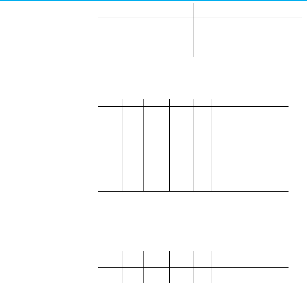
Chapter 4 CIP Axis Attributes
542 Rockwell Automation Publication MOTION-RM003O-EN-P - November 2023
Semantics of Values
Axis Test Mode Support
(Test Mode Configuration)
Enumeration
0 = Axis Instance Created
1 = Connection Created
126 = Axis Inhibited
128 = Axis Configured
Controller Loop Back: v35
Axis State
Usage
Access
Data Type
Default
Min
Max
Semantics of Values
Required -
All
Get
USINT
-
-
-
Enumeration
0 = Ready
1 = Drive Enable, (direct drive
control)
2 = Servo Control
3 = Faulted
4 = Shutdown
5 = Inhibited
6 = Ungrouped
7 = No Module
8 = Configuring (FW default)
State of this instance of the Motion Control Axis. Indicates the operating state
of the axis. Examples of possible states include: axis-ready, drive enable, servo
control, axis faulted, axis shutdown, axis inhibited, and axis unassigned.
Watch Event Task
Usage
Access
Data Type
Default
Min
Max
Semantics of Values
Required -
E
Get DINT - - - -
User Event Task that will be triggered to execute when a Watch event occurs.
This attribute is set through internal communication from the user Task
object to the Axis object when the Task trigger attribute is set to select this
attributes of an Axis. It cannot be set directly by an external device. It is
available to be read externally for diagnostic information.
The Watch Event Task attribute indicates which user Task will be triggered
when a watch event occurs. An instance value of 0 indicates that no event task
has been configured to be triggered by the Watch Event.
The user Task is triggered at the same time that the Process Complete bit is
set for the instruction that armed the watch event.

Chapter 4 CIP Axis Attributes
Rockwell Automation Publication MOTION-RM003O-EN-P - November 2023 543
Registration 1 Event Task
Usage
Access
Data Type
Default
Min
Max
Semantics of Values
Required -
E
Get DINT - - - -
User Event Task that will be triggered to execute when a Registration 1 event
occurs.
This attribute is set through internal communication from the user Task
object to the Axis object when the Task trigger attribute is set to select this
attributes of an Axis. It cannot be set directly by an external device. It is
available to be read externally for diagnostic information.
The Registration 1 Event Task attribute indicates which user Task will be
triggered when a Registration 1 event occurs. An instance value of 0 indicates
that no event task has been configured to be triggered by the Registration 1
Event.
The user Task is triggered at the same time that the Process Complete bit is
set for the instruction that armed the registration event.
Registration 2 Event Task
Usage Access Data Type Default Min Max Semantics of Values
Required -
E
Get DINT - - - -
User Event Task that will be triggered to execute when a Registration 2 event
occurs.
This attribute is set through internal communication from the user Task
object to the Axis object when the Task trigger attribute is set to select this
attributes of an Axis. It cannot be set directly by an external device. It is
available to be read externally for diagnostic information.
The Registration 2 Event Task attribute indicates which user Task will be
triggered when a Registration 2 event occurs.An instance value of 0 indicates
that no event task has been configured to be triggered by the Registration 2
Event.
The user Task is triggered at the same time that the Process Complete bit is
set for the instruction that armed the registration event.
Home Event Task
Usage Access Data Type Default Min Max Semantics of Values
Required -
E
Get DINT - - - -
User Event Task that will be triggered to execute when a Home event occurs.

Chapter 4 CIP Axis Attributes
544 Rockwell Automation Publication MOTION-RM003O-EN-P - November 2023
This attribute is set through internal communication from the user Task
object to the Axis object when the Task trigger attribute is set to select this
attributes of an Axis. It cannot be set directly by an external device. It is
available to be read externally for diagnostic information.
The Home Event Task attribute indicates which user Task will be triggered
when a home event occurs. An instance value of 0 indicates that no event task
has been configured to be triggered by the Home Event.
The user Task is triggered at the same time that the Process Complete bit is
set for the instruction that armed the home event.
Inhibit Axis
Usage
Access
Data Type
Default
Min
Max
Semantics of Values
Required -
All
Set/
SSV
SINT 0 - - 0 triggers an uninhibit.
1 triggers an inhibit.
Setting to any non-zero value is
treated the same as a value of 1, and
results in the attribute being set to a
1.
Used to initiate putting an axis into the inhibit state.
This feature is designed for the following situations:
• To park an unused or faulted axis so that the application program can
continue to run without the unused or faulted axis.
• To allow a 'generic' application program to be developed for a family of
similar machines that may vary in axis count such that it can be
configured during runtime to match the configuration of the specific
machine.
The on-line inhibit process is an intrusive operation in that it impacts all axes
associated to the same motion module as the one being inhibited. As such it is
expected that the users will trigger this operation with the machine in a safe,
non-operating, state. The inhibit process includes breaking connection to the
associated motion module and then allowing the module to be reconfigured
with or without (depending if you are inhibiting or un-inhibiting) this axis.
The inhibit/un-inhibit operation will also stop all motion on all axes
associated to the same motion module including breaking all gearing
relationships. This stop operation follows that of the shutdown fault action;
servo action is immediately disabled as is the drives power structure. Unless
some external form of braking capability is applied the axis will generally
coast to a stop.

Chapter 4 CIP Axis Attributes
Rockwell Automation Publication MOTION-RM003O-EN-P - November 2023 545
Axis Test Mode
Axes with the Test Mode attribute set to Enabled and that are configured for
Controller Loop Back support inhibiting and un-inhibiting individual axes.
Axis ID
Usage
Access
Data Type
Default
Min
Max
Semantics of Values
Required -
All
Set/
GSV
DINT - - - ID
Unique number assigned to axis on creation by configuration software.
The Axis ID is used by the Absolute Position Recovery feature during a
configuration software download to determine if a given axis is a new axis or
pre-existing axis. If the axis existed prior to the download, the controller saves
critical absolute position data associated with the axis before continuing the
download. Using the Axis ID, the controller is able to match the saved absolute
position data with the pre-existing axis and recover absolute position. Using
the saved data, absolute position will be recomputed to account for any
motion that occurred while the download was in process or while power was
off.
Axis Update Schedule
Usage
Access
Data Type
Default
Min
Max
Semantics of Values
Required -
All
Set/
GSV
USINT - - - Enumeration:
0 = Base
1 = Alternate 1
2 = Alternate 2
3-255 = Reserved
Determines the update schedule for the associated axis instance.
The default schedule setting of Base results in the axis being updated with
every Base Update Period of the Motion Task, or the Base Update Period of the
Motion Group. Alternate 1 and Alternate 2 schedule selections result in the
axis being updated at multiples of the Base Update Period given by the
Alternate 1 and Alternate 2 Update Multiplier attribute values of the Motion
Group, or Motion Task or Alternate 1 Update Period and Alternate 2 Update
Period, respectively.
Axis Data Type
Usage
Access
Data Type
Default
Min
Max
Semantics of Values

Chapter 4 CIP Axis Attributes
546 Rockwell Automation Publication MOTION-RM003O-EN-P - November 2023
Usage
Access
Data Type
Default
Min
Max
Semantics of Values
Required -
All
GSV USINT - - - Enumeration:
0 = Feedback
1 = Consumed
2 = Virtual
3 = Generic
4 = Servo
5 = Servo Drive
6 = Generic Drive
7 = CIP Drive
Associated tag data type for this instance of the Motion Control Axis Object.
The Axis Data Type attribute and is used to determine which data template,
memory format, and set of attributes are created and applicable for this axis
instance.
See also
CIP Axis Attributes on page 261
Motion Control Axis Behavior Model on page 60
The Motion Control Signal Attributes associated with the axis provide access
to the current and historical position, velocity, and acceleration information
of the axis. These values may be used as part of the user program to
implement sophisticated real-time computations associated with motion
control applications.
Important:
Configuration of Scaling page parameters is required for any attributes expressed in
position, velocity, or acceleration units to return meaningful values.
All Motion Control Signal Attributes support Direct Tag Access through the
Logix Designer application. Thus, a Motion Signal attribute may be directly
referenced in a program as <axis tag name>.<motion status tag name>. For
example, FeedAxis.ActualPosition.
To avoid the unnecessary processor effort associated with real-time
conversion of certain Motion Status tags that are not of interest to the user,
you need to explicitly activate real-time update of these attributes using the
Auto Tag Update attribute of the associated motion group. A subset of the
Motion Control Signal Attributes must have the Auto Tag Update attribute
enabled to perform scaling conversion. If disabled, the tag value will be forced
to zero. The following attributes are impacted:
• Actual Position
• Actual Velocity
• Actual Acceleration
• Master Offset
• Command Position
• Command Velocity
Motion Control Signal
Attributes

Chapter 4 CIP Axis Attributes
Rockwell Automation Publication MOTION-RM003O-EN-P - November 2023 547
• Command Acceleration
• Average Velocity
The following are the signal attributes associated a Motion Control Axis:
Actual Position
Usage
Access
T
Data
Type
Default
Min
Max
Semantics of Values
Required - All Get/GSV T REAL - - - Position Units
Tag access is supported by the
value is valid only when Auto
Tag Update of the Motion
Group Object is enabled.
The Actual Position attribute is the current absolute position of an axis, in the
configured Position Units of that axis. This value is based on data reported to
the Logix Processor as part of an ongoing synchronous data transfer process
which results in a delay of one Coarse Update Period. Thus, the Actual
Position value that is obtained is the actual position of the axis one Coarse
Update Period ago.
Tag access supported but value is valid only when Auto Tag Update of the
Motion Group Object is enabled.
Axis Test Mode
Axes with the Test Mode attribute set to Enabled and that are configured for
Controller Loop Back tracks the commanded position perfectly with a
simulated delay of two controller updates.
Strobe Actual Position
Usage
Access
T
Data
Type
Default
Min
Max
Semantics of Values
Required - All
Get/GSV
T
REAL
-
-
-
Position Units
Strobe Command Position
Usage
Access
T
Data
Type
Default
Min
Max
Semantics of Values
Required - FPV
Get/GSV
T
REAL
-
-
-
Position Units
Strobe Actual Position and Strobe Command Position attributes are used to
simultaneously store a snap-shot of the actual, command position, and master
offset position of an axis when the MGSP (Motion Group Strobe Position)
instruction is executed. The values are stored in the configured Position Units
of the axis.

Chapter 4 CIP Axis Attributes
548 Rockwell Automation Publication MOTION-RM003O-EN-P - November 2023
Since the MGSP instruction simultaneously stores the actual and command
positions for all axes in the specified group of axes, the resultant Strobe Actual
Position and Strobe Command Position values for different axes can be
used to perform real-time calculations.
For example, the Strobe Actual Positions can be compared between two axes
to provide a form of slip compensation in web handling applications.
Start Position and Start Command Position
Usage
Access
T
Data
Type
Default
Min
Max
Semantics of Values
Required - FPV
Get/GSV
T
REAL
-
-
-
Position Units
Whenever a new motion planner instruction starts for an axis (for example,
using a MAM instruction), the value of the axis command position and actual
position is stored at the precise instant the motion begins. These values are
stored as the Start Command Position and Start Actual Position respectively
in the configured Position Units of the axis.
Start Positions are useful to correct for any motion occurring between the
detection of an event and the action initiated by the event. For instance, in coil
winding applications, Start Command Positions can be used in an expression
to compensate for overshooting the end of the bobbin before the gearing
direction is reversed.
If you know the position of the coil when the gearing direction was supposed
to change, and the position at which it actually changed (the Start Command
Position), you can calculate the amount of overshoot, and use it to correct the
position of the wire guide relative to the bobbin.
Average Velocity
Usage
Access
T
Data
Type
Default
Min
Max
Semantics of Values
Required - All
Get/GSV
T
REAL
-
-
-
Position Units / Sec
The Average Velocity attribute is the current speed and direction of an axis in
the configured Position Units per second of the axis.
Unlike the Actual Velocity attribute value, it is calculated by averaging the
actual velocity of the axis over the configured Average Velocity Timebase for
that axis. Average velocity is a signed value with the sign indicating the
direction the axis is currently moving.
The resolution of the Average Velocity variable is determined by the current
value of the Averaged Velocity Timebase parameter, and the configured
Conversion Constant (feedback counts per Position Unit) for the axis. The
Average Velocity Timebase determines the length over which the Average

Chapter 4 CIP Axis Attributes
Rockwell Automation Publication MOTION-RM003O-EN-P - November 2023 549
Velocity is computed. The greater the Average Velocity Timebase value, the
better the speed resolution, but the slower the response to changes in speed.
The Average Velocity resolution in Position Units per second may be
calculated using this equation.
For example, on an axis with position units of inches and a conversion
constant (K) of 20000, an averaged velocity time-base of 0.25 seconds results
in an average velocity resolution of:
The minimum Average Velocity Timebase value is one Coarse Update Period
defined by the associated Motion Group Object.
Tag access supported but value is valid only when Auto Tag Update of the
Motion Group Object is enabled.
Actual Velocity
Usage
Access
T
Data
Type
Default
Min
Max
Semantics of Values
Required - All Get/
GSV
T REAL - - - Position Units / Sec
Tag access is supported but
the value is valid only when
Auto Tag Update of the Motion
Group Object is enabled.
The Actual Velocity attribute is the current instantaneously measured speed
and direction of an axis, in the configured axis Position Units per second. It is
calculated as the current increment to the actual position per coarse update
interval.
Actual Velocity is a signed floating point value—the sign (+ or -) depends on
which direction the axis is currently moving. Its resolution does not depend
on the Averaged Velocity Timebase, but rather on the conversion constant of
the axis and the fact that the internal resolution limit on actual velocity is 1
feedback count per coarse update.
Tag access supported but value is valid only when Auto Tag Update of the
Motion Group Object is enabled.
Actual Acceleration
Usage
Access
T
Data
Type
Default
Min
Max
Semantics of Values

Chapter 4 CIP Axis Attributes
550 Rockwell Automation Publication MOTION-RM003O-EN-P - November 2023
Usage
Access
T
Data
Type
Default
Min
Max
Semantics of Values
Required - All Get/
GSV
T REAL - - - Position Units / Sec
2
Tag access supported but the
value is valid only when Auto
Tag Update of the Motion
Group Object is enabled.
The Actual Acceleration attribute is the current instantaneously measured
acceleration of an axis in the configured axis Position Units per second per
second. It is calculated as the current increment to the actual velocity per
coarse update interval.
Actual Acceleration is a signed floating-point value. Its resolution does not
depend on the Averaged Velocity Timebase, but rather on the Conversion
Constant of the axis and the fact that the internal resolution limit on actual
velocity is 1 feedback count per Coarse Update Period
2
.
Tag access supported but value is valid only when Auto Tag Update of the
Motion Group Object is enabled.
Watch Position
Usage Access T Data
Type
Default Min Max Semantics of Values
Required - E Get/
GSV
T REAL - - - Position Units
The Watch Position attribute is the current set-point position of an axis, in the
configured axis Position Units, as set up in the last, most recently executed,
MAW (Motion Arm Watch) instruction for that axis.
Registration 1 Position and Registration 2 Position
Usage
Access
T
Data
Type
Default
Min
Max
Semantics of Values
Required - E Get/
GSV
T REAL - - - Position Units
Two registration position attributes are provided to independently store axis
position associated with two different registration input events. The
Registration Position value is the absolute position of a physical or virtual axis
(in the position units of that axis) at the occurrence of the most recent
registration event for that axis.
This figure shows how the registration position is latched by the registration
input when a registration event occurs. The latching mechanism can be
implemented in the controller software (soft registration) or, for greater
accuracy, in physical hardware (hard registration).

Chapter 4 CIP Axis Attributes
Rockwell Automation Publication MOTION-RM003O-EN-P - November 2023 551
The Registration Latch mechanism is controlled two Event Control
instructions, MAR (Motion Arm Registration) and MDR (Motion Disarm
Registration).
The accuracy of the registration position value, saved as a result of a
registration event, is a function of the delay in recognizing the specified
transition (typically 1 µsec for hardware registration) and the speed of the axis
during this time. The uncertainty in the registration position is the distance
traveled by the axis during this interval as shown in this equation:
Use the formula given above to calculate the maximum registration position
error for the expected axis speed. Alternatively, you can calculate the
maximum axis speed for a specified registration accuracy by re-arranging this
formula:
Registration 1 Time and Registration 2 Time
Usage
Access
T
Data
Type
Default
Min
Max
Semantics of Values
Required - E Get/
GSV
T DINT - - - CST time in microseconds
The two Registration Time values contain the lower 32-bits of CST time at
which their respective registration events occurred. Units for this attribute
are in microseconds.
Interpolation Time
Usage
Access
T
Data
Type
Default
Min
Max
Semantics of Values
Required - E Set/
SSV
T DINT - - - CST time to Interpolation
The Interpolation Time attribute is the 32-bit CST time used to calculate the
interpolated positions. When this attribute is updated with a valid CST value,
the Interpolated Actual Position and Interpolated Command Position values
are automatically calculated.

Chapter 4 CIP Axis Attributes
552 Rockwell Automation Publication MOTION-RM003O-EN-P - November 2023
Interpolated Actual Position
Usage
Access
T
Data
Type
Default
Min
Max
Semantics of Values
Required - E Get/
GSV
T REAL - - - Position Units
The Interpolated Actual Position attribute is the interpolation of the actual
position, based on past axis trajectory history, at the time specified by the
Interpolation Time attribute.
Command Position
Usage
Access
T
Data
Type
Default
Min
Max
Semantics of Values
Required - FPV Get/
GSV
T REAL - - - Position Units
Tag access is supported but
the value is valid only when
Auto Tag Update of the Motion
Group Object is enabled.
The Command Position attribute is the desired or commanded position of a
physical axis, in the configured Position Units of that axis, as generated by the
controller in response to any previous motion Position Control instruction.
Command Position data is transferred by the Logix Processor to a physical
axis as part of an ongoing synchronous data transfer process which results in
a delay of one Coarse Update Period. Thus, the Command Position value that
is obtained is the command position that will be acted upon by the physical
servo axis one Coarse Update Period from now.
The figure below shows the relationship between Actual Position, Command
Position, and Position Error for an axis with an active servo loop. Actual
Position is the current position of the axis as measured by the feedback
device, for example an encoder. Position error is the difference between the
Command and Actual Positions of the servo loop, and is used to drive the
motor to make the actual position equal to the command position.
Command position is useful when performing motion calculations and
incremental moves based on the current position of the axis while the axis is
moving. Using command position rather than actual position avoids the
introduction of errors due to the position error of the axis at the time the
calculation is performed.
Tag access supported but value is valid only when Auto Tag Update of the
Motion Group Object is enabled.

Chapter 4 CIP Axis Attributes
Rockwell Automation Publication MOTION-RM003O-EN-P - November 2023 553
Axis Test Mode
Axes with the Test Mode attribute set to Enabled and that are configured for
Controller Loop Back copy the commanded position, with a simulated
controller-drive interface delay. This results in a zero position error.

Chapter 4 CIP Axis Attributes
554 Rockwell Automation Publication MOTION-RM003O-EN-P - November 2023
Strobe Command Position
Usage
Access
T
Data
Type
Default
Min
Max
Semantics of Values
Required - FPV Get/
GSV
T REAL - - - Position Units
Strobe Actual Position, Strobe Command Position and Strobe Master Offset
attributes are used to simultaneously store a snap-shot of the actual,
command position, and master offset position of an axis when the MGSP
(Motion Group Strobe Position) instruction is executed. The values are stored
in the configured Position Units of the axis.
Since the MGSP instruction simultaneously stores the actual and command
positions for all axes in the specified group of axes, the resultant Strobe Actual
Position, Strobe Command Position and Strobe Master Offset values for
different axes can be used to perform real-time calculations. For example, the
Strobe Actual Positions can be compared between two axes to provide a form
of slip compensation in web handling applications.
Start Command Position
Usage
Access
T
Data
Type
Default
Min
Max
Semantics of Values
Required - FPV Get/
GSV
T REAL - - - Position Units
Whenever a new motion planner instruction starts for an axis (for example,
using a MAM instruction), the value of the axis command position and actual
position is stored at the precise instant the motion begins. These values are
stored as the Start Command Position and Start Actual Position respectively
in the configured Position Units of the axis.
Start Positions are useful to correct for any motion occurring between the
detection of an event and the action initiated by the event. For instance, in coil
winding applications, Start Command Positions can be used in an expression
to compensate for overshooting the end of the bobbin before the gearing
direction is reversed.
If you know the position of the coil when the gearing direction was supposed
to change, and the position at which it actually changed (the Start Command
Position), you can calculate the amount of overshoot, and use it to correct the
position of the wire guide relative to the bobbin.
Command Velocity
Usage
Access
T
Data
Type
Default
Min
Max
Semantics of Values

Chapter 4 CIP Axis Attributes
Rockwell Automation Publication MOTION-RM003O-EN-P - November 2023 555
Usage
Access
T
Data
Type
Default
Min
Max
Semantics of Values
Required - FPV Get/
GSV
T REAL - - - Position Units / Sec
Tag access is supported but
the value is valid only when
Auto Tag Update of the Motion
Group Object is enabled.
The Command Velocity is the commanded speed and direction of an axis, in
the configured axis Position Units per second, as generated by any previous
motion instructions. It is calculated as the current increment to the command
position per coarse update interval. Command Velocity is a signed value—the
sign (+ or -) depends on which direction the axis is being commanded to
move.
Command Velocity is a signed floating-point value. Its resolution does not
depend on the Averaged Velocity Timebase, but rather on the conversion
constant of the axis and the fact that the internal resolution limit on
command velocity is 0.00001 feedback counts per coarse update.
Tag access supported but value is valid only when Auto Tag Update of the
Motion Group Object is enabled.
Command Acceleration
Usage
Access
T
Data
Type
Default
Min
Max
Semantics of Values
Required - FPV Get/
GSV
T REAL - - - Position Units / Sec
2
Tag access is supported but
the value is valid only when
Auto Tag Update of the Motion
Group Object is enabled.
The Command Acceleration attribute is the commanded speed and direction
of an axis, in the configured axis Position Units per second per second, as
generated by any previous motion instructions. It is calculated as the current
increment to the command velocity per coarse update interval. Command
Acceleration is a signed value: the sign (+ or -) depends on which direction the
axis is being commanded to move.
Command Acceleration is a signed floating-point value. Its resolution does
not depend on the Averaged Velocity Timebase, but rather on the conversion
constant of the axis and the fact that the internal resolution limit on
command velocity is 0.00001 feedback counts per Coarse Update Period
2
.
Tag access supported but value is valid only when Auto Tag Update of the
Motion Group Object is enabled.

Chapter 4 CIP Axis Attributes
556 Rockwell Automation Publication MOTION-RM003O-EN-P - November 2023
Command Torque
Usage
Access
T
Data
Type
Default
Min
Max
Semantics of Values
Required - VT Get/
SSV
T REAL 0
- +
% Rated
The Command Torque attribute is the commanded torque in units of percent
Rated Torque of the motor. This tag value is transferred by the Logix
Processor to a physical axis as part of an ongoing synchronous data transfer
process. Unlike Command Position, Command Velocity, and Command
Acceleration, the Command Torque attribute is not generated by the motion
planner. Instead, the value may be written directly by the application
program.
Command Torque has no effect on the axis unless the axis is configured for
Torque Loop operation. In order for the this attribute's value to be applied as
the torque command, a Motion Drive Start instruction will be executed, which
in turn sets the Direct Torque Control Status bit of the Motion Status Bits
attribute. If this bit is not set, the Command Torque value has no effect on
axis motion. Only CIP Drive Axis data types currently support this capability.
Interpolated Command Position
Usage
Access
T
Data
Type
Default
Min
Max
Semantics of Values
Required - E
PV only
Get/
GSV
T REAL - - - Position Units
The Interpolated Command Position attribute is the interpolation of the
commanded position, based on past axis trajectory history, at the time
specified by the Interpolation Time attribute.
Master Offset
Usage
Access
T
Data
Type
Default
Min
Max
Semantics of Values
Required - FPV
PV only
Get/
GSV*
T REAL - - - Master Position Units
Tag access supported but the
value is valid only when Auto
Tag Update of the Motion
Group Object is enabled.
The Master Offset attribute is the position offset that is currently applied to
the master side of the position cam. The Master Offset is returned in master
position units. The Master Offset shows the same unwind characteristic as the
position of a linear axis. Tag access is supported but the tag value is valid only
when Auto Tag Update of the Motion Group Object is enabled

Chapter 4 CIP Axis Attributes
Rockwell Automation Publication MOTION-RM003O-EN-P - November 2023 557
Strobe Master Offset
Usage
Access
T
Data
Type
Default
Min
Max
Semantics of Values
Required - FPV
PV only
Get/
GSV
T REAL - - - Master Position Units
The Strobe Master Offset attribute is the position offset that was applied to
the master side of the position cam when the last Motion Group Strobe
Position (MGSP) instruction was executed. The Strobe Master Offset is
returned in master position units. The Strobe Master Offset shows the same
unwind characteristic as the position of a linear axis.
Start Master Offset
Usage
Access
T
Data
Type
Default
Min
Max
Semantics of Values
Required - FPV
PV only
Get/
GSV
T REAL - - - Master Position Units
The Start Master Offset attribute is the position offset that was applied to the
master side of the position cam when the last Motion Axis Move (MAM)
instruction with the move type set to Absolute Master Offset or Incremental
Master Offset was executed. The Start Master Offset is returned in master
position units. The Start Master Offset shows the same unwind characteristic
as the position of a linear axis.
Direct Command Velocity
Usage
Access
T
Data
Type
Default
Min
Max
Semantics of Values
Required - FV Get/
SSV
T REAL -
- +
Position Units / Sec
The Direct Command Velocity attribute provides tag access to the velocity
command for the specified axis. This can be used to directly control the speed
of a motor when an associated drive is configured for velocity control mode.
In order for this attribute's value to be applied as the velocity command, a
Motion Drive Start instruction will be executed, which in turn sets the Direct
Velocity Control Status bit of the Motion Status Bits attribute. If this bit is not
set, the Direct Command Velocity value has no effect on axis motion. Only CIP
Drive Axis data types currently support this capability.
Interpolated Position Configuration
Usage Access T Data Type Default Min Max Semantics of Values

Chapter 4 CIP Axis Attributes
558 Rockwell Automation Publication MOTION-RM003O-EN-P - November 2023
Usage
Access
T
Data Type
Default
Min
Max
Semantics of Values
Required - E Set/
SSV
T DWORD 0:0
1:1
- - Bitmap
0 = 2
nd
Order Actual Position
Interpolation
1 = 2
nd
Order Command
Position Interpolation
This bit mapped attribute configures the interpolation algorithm used to
calculate Interpolated Actual Position and Interpolated Command Position
based on axis position history based on the current value of Interpolation
Time.
The 2
nd
Order Actual Position Interpolation bit controls the order of the
interpolation algorithm used to calculate Interpolated Actual Position based
on Interpolation Time. If the bit is set, 2
nd
order interpolation is used. If the
bit is clear, 1
st
order interpolation is used. Generally, 2
nd
order interpolation
results in more accurate estimates of position, but if the actual position signal
has high levels of quantization noise, 1
st
order interpolation gives better
results.
The 2nd Order Command Position Interpolation bit controls the order of the
interpolation algorithm used to calculate Interpolated Command Position
based on Interpolation Time. If the bit is set, 2
nd
order interpolation is used. If
the bit is clear, 1
st
order interpolation is used. Generally, 2
nd
order
interpolation results in more accurate estimates of position, but if the
command position signal has high levels of quantization noise, 1
st
order
interpolation gives better results.
See also
Motion Control Interface Attributes on page 537
These are the motion control status attributes associated with a Motion
Control Axis. The Axis Event Bits are located in Event Capture Attributes.
Motion Control Status
Attributes

Chapter 4 CIP Axis Attributes
Rockwell Automation Publication MOTION-RM003O-EN-P - November 2023 559
Motion Status Bits
Usage
Access
T
Data Type
Default
Min
Max
Semantics of Values
Required -
All
Get/
GSV
1
T DWORD - - - Bitmap
0 = AccelStatus
1 = DecelStatus
2 = MoveStatus
3 = JogStatus
4 = GearingStatus
5 = HomingStatus
6 = StoppingStatus
7 = AxisHomedStatus
8 = PositionCamStatus
9 = TimeCamStatus
10 = PositionCamPendingStatus
11 = TimeCamPendingStatus
12 = GearingLockStatus
13 = PositionCamLockStatus
14 = TimeCamLockStatus
15 = MasterOffsetMoveStatus
16 = CoordinatedMotionStatus
17 = TransformStateStatus
18 = ControlledByTransformStatus
19 = DirectVelocityControlStatus
20 = DirectTorqueControlStatus
21 = Reserved
22 = MoveLockStatus
23 = Reserved
24 = JogLockStatus
25 = MasterOffsetMovePendingStatus
26 = MasterOffsetMoveLockStatus
27 = MaximumSpeedExceeded
28...31 = Reserved
1
Direct Tag access is supported. Bit names shown are used as data type member names in the Logix Designer application.
This is a bitmapped collection of status conditions associated with the motion
planner function.
Motion Axis Status Bits Descriptions
This table provides descriptions of the various Motion Axis Status Bits:
Bit
Motion Status
Description
0
Accel Status
The Acceleration and Deceleration Status bit attributes (AccelStatus and
DecelStatus) can be used to determine if the axis is currently being commanded
to accelerate or decelerate. If neither bit is set then the axis is running at steady
state velocity or at rest.
1 Decel Status
2 Move Status The MoveStatus bit attribute is set if a Move motion profile is currently in
progress. As soon as the Move is complete or superseded by some other motion
operation, the MoveStatus bit is cleared.

Chapter 4 CIP Axis Attributes
560 Rockwell Automation Publication MOTION-RM003O-EN-P - November 2023
Bit
Motion Status
Description
3 Jog Status The JogStatus bit attribute is set if a Jog motion profile is currently in progress.
As soon as the Jog is complete or superseded by some other motion operation,
the JogStatus bit is cleared.
4 Gearing Status The GearingStatus bit attribute is set if the axis is currently Gearing to another
axis. As soon as the gearing operation is stopped or superseded by some other
motion operation, the GearStatus bit is cleared.
5 Homing Status The HomingStatus bit attribute is set if a Home motion profile is currently in
progress. As soon as the Home is complete or superseded by some other motion
operation, the HomeStatus bit is cleared.
6 Stopping Status The StoppingStatus bit attribute is set if there is a stopping process currently in
progress. As soon as the stopping process is complete, the Stopping Status bit
is cleared.
The stopping process is used to stop an axis (initiated by an MAS, MGS, MGSP,
Stop Planner fault action, or mode change). This bit is no longer associated with
the gearing Clutch bit (MAG with Clutch selected), which for I4B has been
explicitly named the GearingLockStatus bit.
7 Homed Status The HomedStatus bit attribute is cleared at powerup or reconnection. The bit is
set to 1 by the MAH instruction upon successful completion of the configured
homing sequence. This bit would be later cleared if the axis entered the
shutdown state.
The HomedStatus bit is set by the MAH instruction upon successful completion
of the configured homing sequence. This bit indicates that an absolute machine
reference position has been established. When this bit is set, operations that
require a machine reference, such as Software Overtravel checking can be
meaningfully enabled.
The HomedStatus bit is cleared under the following conditions:
1. Download, Control power cycle, or Reconnection with Incremental Feedback
device.
2. Absolute Position Recovery (APR) fails with Absolute Feedback device.
3. Feedback Integrity bit is cleared by CIP Motion drive.
The HomedStatus bit is directly used by the control system to qualify the
Software Overtravel checking function. Thus, if the HomedStatus bit is clear,
Soft Overtravel checking will not occur even if the Soft Overtravel Checking bit is
set.
8 Position Cam Status The PositionCamStatus bit attribute is set if a Position Cam motion profile is
currently in progress. As soon as the Position Cam is complete or superseded by
some other motion operation, the PositionCamStatus bit is cleared.
9 Time Cam Status The TimeCamStatus bit attribute is set if a Time Cam motion profile is currently
in progress. As soon as the Time Cam is complete or superseded by some other
motion operation, the TimeCamStatus bit is cleared.
10 Position Cam
Pending Status
The PositionCamPendingStatus bit attribute is set if a Position Cam motion
profile is currently pending the completion of a currently executing cam profile.
This would be initiated by executing an MAPC instruction with Pending execution
selected.
As soon as the current position cam profile completes, initiating the start of the
pending cam profile, the PositionCamPending Status bit is cleared. This bit is
also cleared if the position cam profile completes, or superseded by some other
motion operation.

Chapter 4 CIP Axis Attributes
Rockwell Automation Publication MOTION-RM003O-EN-P - November 2023 561
Bit
Motion Status
Description
11 Time Cam Pending
Status
The TimeCamPendingStatus bit attribute is set if a Time Cam motion profile is
currently pending the completion of a currently executing cam profile. This
would be initiated by executing an MATC instruction with Pending execution
selected.
As soon as the current time cam profile completes, initiating the start of the
pending cam profile, the TimeCamPending status bit is cleared. This bit is also
cleared if the time cam profile completes, or superseded by some other motion
operation.
12 Gearing Lock Status The GearingLockStatus bit attribute is set whenever the slave axis is locked to
the master axis in a gearing relationship according to the specified gear ratio.
The clutch function of the gearing planner is used to ramp an axis up, or down,
to speed in a gearing process (MAG with Clutch selected). During the intervals
where the axis is clutching, the GearingLockStatus bit is clear.
13 Position Cam Lock
Status
The PositionCamLockStatus bit attribute is set whenever the master axis
satisfies the starting condition of a currently active Position Cam motion profile.
The starting condition is established by the Start Control and Start Position
parameters of the MAPC instruction.
As soon as the current position cam profile completes, or is superseded by
some other motion operation, the Position Cam Lock bit is cleared. In
unidirectional master direction mode, the PositionCamLockStatus bit clears
when moving in the wrong direction and sets when moving in the correct
direction.
15 Master Offset Move
Status
The MasterOffsetMoveStatus bit attribute is set if a Master Offset Move motion
profile is currently in progress.
As soon as the Master Offset Move is complete or superseded by some other
motion operation, the MasterOffsetMoveStatus bit is cleared.
16 Coordinated Motion
Status
The CoordinatedMotionStatus bit attribute is set if any coordinated motion
profile is currently active upon this axis.
As soon as the Coordinated Motion is complete or stopped, the
CoordinatedMotionStatus bit is cleared.
17 Transform State
Status
The Transform State Status bit is set if the axis in involved in a transform. The
axis is in one of the coordinate systems specified in an active MCT instruction.
True will indicate the axis is involved in a transform, false will indicate it is not.
18 Controlled By
Transform Status
The Controlled By Transform Status bit is set if the axis is under transform
control. True indicates the axis is under transform control and false indicates it
is not under transform control. An axis under transform control cannot be
commanded to move.
19 Direct Velocity
Control Status
When the Direct Velocity Control Status bit is set, the axis speed is directly
controlled by the Direct Command Velocity value.
This bit is set by the Motion Drive Start instruction (MDS) and only applies to CIP
Drive axis types.
20 Direct Torque
Control Status
When the Direct Torque Control Status bit is set, the axis torque is directly
controlled by the Command Torque value.
This bit is set by the Motion Drive start instruction (MDS) and only applies to CIP
Drive axis types.
22 Move Lock Status The MoveLockStatus bit is set when the master axis satisfies the Lock Direction
request of a Motion Axis Move (MAM) Instruction. If the Lock Direction is
Immediate Forward Only or Immediate Reverse Only the MoveLockStatus bit will
be set immediately when the MAM is initiated. If the Lock Direction is Position
Forward Only or Position Reverse Only the bit will be set when the Master Axis
crosses the Master Lock Position in the specified direction.
The MoveLockStatus bit is cleared when the Master Axis reverses direction and
the Slave Axis stops following the Master Axis. The MoveLockStatus bit is set
again when the Slave Axis resumes following the Master Axis.

Chapter 4 CIP Axis Attributes
562 Rockwell Automation Publication MOTION-RM003O-EN-P - November 2023
Bit
Motion Status
Description
24 Jog Lock Status The JogLockStatus bit is set when the master axis satisfies the Lock Direction
request of a Motion Axis Jog (MAJ) Instruction. If the Lock Direction is Immediate
Forward Only or Immediate Reverse Only the JogLockStatus bit will be set
immediately when the MAJ is initiated. If the Lock Direction is Position Forward
Only or Position Reverse Only the bit will be set when the Master Axis crosses the
Master Lock Position in the specified direction.
The JogLockStatus bit is cleared when the Master Axis reverses direction and
the Slave Axis stops following the Master Axis. The JogLockStatus bit is set again
when the Slave Axis resumes following the Master Axis.
25 Master Offset Move
Pending Status
The Master offset Move locks to master in the MDSC mode.
26 Master Offset Move
Lock Status
The MasterOffsetMoveLockStatus bit is set when the master axis satisfies the
Lock Direction request of a Master Offset Move executed using MAM instruction.
If the Lock Direction is Immediate Forward Only or Immediate Reverse Only the
MasterOffsetMoveLockStatus bit will be set immediately when the MAM is
initiated. If the Lock Direction is Position Forward Only or Position Reverse Only
the bit will be set when the Master Axis crosses the Master Lock Position in the
specified direction.
The MasterOffsetMoveLockStatus bit is cleared when the Master Axis reverses
direction and the Slave Axis stops following the Master Axis. The
MasterOffsetMoveLockStatus bit is set again when the Slave Axis resumes
following the Master Axis.
27 Maximum Speed
Exceeded
The MaximumSpeedExceeded bit is set when the axis command velocity at any
time exceeds the maximum speed configured for an axis. The bit will be cleared
when the axis velocity is reduced below the maximum speed.
Axis Status Bits
Usage
Access
T
Data Type
Default
Min
Max
Semantics of Values
Required - All Get/
GSV
1
T DWORD - - - 0 = ServoActionStatus
1 = DriveEnableStatus
2 = AxisShutdownStatus
3 =
ConfigurationUpdateInProcess
4 = InhibitStatus
5 = DirectControlStatus
6 = AxisUpdateStatus
7...31 = Reserved
1
Direct Tag access is supported. Bit names shown are used as data type member names in the Logix Designer
application.
The Axis Status Bits attribute is a collection of basic status conditions
associated with the axis. These represent key status conditions used by the
system in executing motion control instructions.
This table provides descriptions of the Axis Status Bits:
Bit
Axis Status
Description
0 Servo Action
Status
The ServoActionStatus bit attribute is set when the associated axis motor control
function is tracking command reference from the controller.
1 Drive Enable
Status
The DriveEnableStatus bit attribute is set when the power structure associated
with the axis is currently enabled. If the bit is not set then the power structure
associated with the axis is currently disabled.

Chapter 4 CIP Axis Attributes
Rockwell Automation Publication MOTION-RM003O-EN-P - November 2023 563
2 Axis Shutdown
Status
The AxisShutdownStatus bit attribute is set when the associated axis is currently
in the Shutdown state. As soon as the axis is transitioned from the Shutdown
state to another state, the Shutdown Status bit is cleared.
3 Configuration
Update in Process
The Configuration Update in Process Status Bits attribute provides a method for
monitoring the progress of one or more specific module configuration attribute
updates initiated by either a Set Attribute List service or an SSV in the user
program. As soon as such an update is initiated, the Logix processor sets the
ConfigurationUpdateInProcess bit.
The bit remains set until the Set Attribute List reply comes back from the servo
module indicating that the data update process was successful. Thus the
Configuration Update In Process Status Bits attribute provides a method of
waiting until the servo configuration data update to the connected motion
module is complete before starting a dependent operation.
4 Inhibit Status An axis may be inhibited or uninhibited programmatically using Attribute #20
Inhibit Axis. The InhibitStatus bit attribute is set when the axis is in the inhibited
state. This bit can also be used to determine when an inhibit/uninhibit operation
has been completed (i.e. connection has been shutdown, reconnected and then
the reconfiguration process completed). During the inhibit/uninhibit process this
bit will remain in the previous state and then once it completes it will be updated
to the new state. This inhibit status is not related to Start Inhibits.
5 Direct Control
Status
When the Direct Control Status bit is set, axis motion is driven by the Direct
Velocity Control and Direct Torque Control functions. In this mode, the Motion
Planner functionality is disabled. So if you attempt to move the axis with a Motion
Planner instruction, for example, MAM, MAJ, and MAG, a ran instruction error
occurs.
In Direct Control, you do not have to establish or maintain absolute reference
position. So, when you attempt to execute the MAH and MRP instructions, an
instruction error occurs.
When the Direct Control Status bit is clear, axis motion is controlled by the Motion
Planner. If you attempt to move the axis in this mode with a Direct Control
instruction, for example, an MDS, an instruction error occurs. This bit only applies
to CIP Drive axis types.
The illustration describes the following behavior.
The Direct Control Status bit is set by the Motion Drive Start instruction (MDS) and
once set, can only be cleared by executing an MSO instruction from the Stopped
or Stopping State. Similarly, once the Direct Control Status bit is cleared by the
Motion Servo On instruction (MSO), the bit can only be set again by executing an
MDS instruction from the Stopped or Stopping State.

Chapter 4 CIP Axis Attributes
564 Rockwell Automation Publication MOTION-RM003O-EN-P - November 2023
6 Axis Update Status The Axis Update bit indicates whether or not this axis instance was updated in
last execution of motion task. In general, axis instances are updated in Motion
Task according to their Axis Update Schedule. Thus, a given axis instance may or
may not be updated during motion task execution. When inspected as part of an
Event Task triggered by motion group or motion task Execution, the Axis Update
bit can be used to qualify program instructions based on whether or not the axis
was updated by the preceding motion task.
Axis Fault Bits
Usage
Access
T
Data Type
Default
Min
Max
Semantics of Values
Required - All Get/GSV
1
T DWORD - - - Bitmap
0 = PhysicalAxisFault
1 = ModuleFault
2 = ConfigurationFault
3 = GroupFault
4 = MotionFault
5 = GuardFault
6 = InitializationFault
7 = APRFault
8 = SafetyFault
9...31 = Reserved
1
Direct Tag access is supported. Bit names shown are used as
data type member names in the Logix Designer
application.
The Axis Fault Bits attribute is a collection of basic fault types associated with
the axis. Each valid axis fault type is assigned a bit in this word. Any fault
condition associated with a given fault type will result in the setting of the
appropriate fault bit.
Each bit in the Axis Fault Bits attribute represents a roll-up of the associated
fault types. One or more faults of a given fault type result in the associated bit
of the Axis Fault Bits attribute being set.
This table provides descriptions of the Axis Fault Bits:
Bit
Name
Description
0 Physical Axis
Fault
If the Physical Axis Fault bit is set, it indicates that one or more fault conditions
have been reported by the physical axis. The specific fault conditions can then be
determined through access to the axis data type specific fault attributes of the
associated physical axis.
For CIP Drive axis data types, Physical Axis Faults map to standard CIP Axis Faults
attribute or manufacturer specific CIP Axis Faults.
1 Module Fault The Module Fault bit attribute is set when one or more faults have occurred related
to the motion module associated with the selected axis. The specific fault
conditions can then be determined through access to the Module Fault attribute of
the associated axis. Usually a module fault impacts all axes associated with the
motion module. A module fault generally results in the shutdown of all associated
axes. Reconfiguration of the motion module is required to recover from a module
fault condition.
2 Configuration
Fault
The Configuration Fault bit is set when an update operation targeting an axis
configuration attribute of an associated motion module has failed. Specific
information concerning the Configuration Fault may be found in the Attribute Error
Code and Attribute Error ID attributes associated with the motion module.

Chapter 4 CIP Axis Attributes
Rockwell Automation Publication MOTION-RM003O-EN-P - November 2023 565
Bit
Name
Description
3 Group Fault The Group Fault bit attribute is set when one or more faults have occurred related
to the motion group associated with the selected axis. The specific fault conditions
can then be determined through access to the Group Fault attribute of the
associated motion group. Usually a group fault impacts all axes associated with the
motion group. A group fault generally results in the shutdown of all associated
axes. Reconfiguration of the entire motion subsystem is required to recover from a
group fault condition.
4 Motion Fault If the Motion Fault bit is set, it indicates that one or more fault conditions have
occurred related to the Motion Planner function. The specific fault conditions can
then be determined through access to the Motion Fault attribute of the associated
axis.
5 Guard Fault If the Guard Fault bit is set, it indicates that one or more fault conditions have
occurred related to the embedded Guard Motion safety function. The specific fault
conditions can then be determined through access to the Guard Fault attribute of
the associated axis. Guard Faults are only applicable if the drive device is equipped
with "Hardwired" Guard Safety functionality.
6 Initialization
Fault
The Initialization Fault bit is set when initialization of a CIP Motion device fails for
any reason. Specific information concerning the Initialization Fault may be found
either in the standard CIP Initialization attributes or in the manufacturer specific
CIP Initialization Fault attributes associated with the CIP Drive axis data types.
7 APR Fault The APR (Absolute Position Recovery) Fault bit is set when during axis configuration
the system is not able to recover the absolute position of the axis. Specific
information concerning the APR Fault may be found either in the standard APR
Fault attributes or int he manufacturer specific APR Fault attributes associated
with the CIP Drive axis data types.
8 Safety Fault If the Safety Fault bit is set, it indicates that there is one or more fault conditions
have occurred related to the axis safety function. The specific fault conditions can
then be determined through access to the Axis Safety Fault attributes of the
associated axis. Safety Faults are only applicable if the motion device supports
"Networked" Safety functionality through a CIP Safety connection.
Axis Test Mode
Axes with the Test Mode attribute set to Enabled and that are configured for
Controller Loop Back simulate these CIP Axis Faults bits.
Bit
Name
Description
Axis Test Mode Support
(Test Mode Configuration)
3 Group Fault Only these faults set the Group Fault bits:
1. CST Loss
2. Clock Sync Fault
4 Motion Fault All Faults generated by Motion Planner results in this bit
being set.
8 Safety Fault Only Motion Safety Functions
Faults are simulated.
Controller Loop Back: v36

Chapter 4 CIP Axis Attributes
566 Rockwell Automation Publication MOTION-RM003O-EN-P - November 2023
Axis Event Bits
Usage Access T Data Type Default Min Max Semantics of Values
Required -
All
Get/GSV
1
T DWORD - - - Bitmap - AxisFault
0 = WatchEventArmedStatus
1 = WatchEventStatus
2 = RegEvent1ArmedStatus
3 = RegEvent1Status
4 = RegEvent2ArmedStatus
5 = RegEvent2Status
6 = HomeEventArmedStatus
7 = HomeEventStatus
8... 31= Reserved
1
Direct Tag access is supported. Bit names shown are
used as data type member names in the Logix Designer
application.
The Axis Event Bit attributes are a collection of basic event conditions. This
attribute is for use primarily by the system during execution of various
Motion Event instructions.
Axis Event Bit Descriptions
Bit
Name
Description
0 Watch Event Armed Status The Watch Event Armed Status bit attribute is set when a
watch event has been armed through execution of the MAW
(Motion Arm Watch) instruction. This bit is cleared when either
a watch event occurs or a MDW (Motion Disarm Watch)
instruction is executed.
1 Watch Event Status The Watch Event Status bit attribute is set when a watch
event has occurred. This bit is cleared when either another
MAW (Motion Arm Watch) instruction or a MDW (Motion Disarm
Watch) instruction is executed.
2 Registration 1 Event Armed Status The Registration 1 Event Armed Status bit attribute is set when
a registration checking has been armed for registration input
1 through execution of the MAR (Motion Arm Registration)
instruction. This bit is cleared when either a registration event
occurs or a MDR (Motion Disarm Registration) instruction is
executed for registration input 1.
3 Registration 1 Event Status The Registration 1 Event Status bit attribute is set when a
registration event has occurred on registration input 1. This
bit is cleared when either another MAR (Motion Arm
Registration) instruction or a MDR (Motion Disarm Registration)
instruction is executed for registration input 1.
4 Registration 2 Event Armed Status The Registration 2 Event Armed Status bit attribute is set
when a registration checking has been armed for registration
input 2 through execution of the MAR (Motion Arm
Registration) instruction. This bit is cleared when either a
registration event occurs or a MDR (Motion Disarm
Registration) instruction is executed for registration input 2.

Chapter 4 CIP Axis Attributes
Rockwell Automation Publication MOTION-RM003O-EN-P - November 2023 567
Bit
Name
Description
5 Registration 2 Event Status The Registration 2 Event Status bit attribute is set when a
registration event has occurred on registration input 2. This
bit is cleared when either another MAR (Motion Arm
Registration) instruction or a MDR (Motion Disarm Registration)
instruction is executed for registration input 2.
6 Home Event Armed Status The Home Event Armed Status bit attribute is set when a
home event has been armed and is used by the MAH (Motion
Axis Home) instruction to manage various homing events that
occur during the configured homing sequence. This bit is
cleared when a home event occurs.
7 Home Event Status The Home Event Status bit attribute is set when a home event
has occurred and is used by the MAH (Motion Axis Home)
instruction to manage various homing events that occur
during the configured homing sequence. This bit is cleared
when another MAH instruction is executed.
Output Cam Status
Usage
Access
T
Data Type
Default
Min
Max
Semantics of Values
Required - E Get/
GSV
1
T DWORD - - - Set of Output Cam Status bits.
1
Direct Tag access is supported. Bit names shown are used as data type member names in the Logix
Designer application.
The Output Cam Status bit is set when an Output Cam has been initiated. The
Output Cam Status bit is reset when the cam position moves beyond the cam
start or cam end position in "Once" execution mode with no Output Cam
pending or when the Output Cam is terminated by a Motion Disarm Output
Cam (MDOC) instruction.
Output Cam Pending Status
Usage
Access
T
Data Type
Default
Min
Max
Semantics of Values
Required - E Get/
GSV
1
T DWORD - - - Set of Output Cam Pending
Status bits.
1
Direct Tag
access is supported. Bit names shown are used as data type member names in the Logix Designer
application.
The Output Cam Pending Status bit is set if an Output Cam is currently
pending the completion of another Output Cam. This would be initiated by
executing an Motion Arm Output Cam (MAOC) instruction with Pending
execution selected. As soon as this output cam is armed, being triggered when
the currently executing Output Cam has completed, the Output Cam Pending
bit is cleared. This bit is also cleared if the Output Cam is terminated by a
Motion Disarm Output Cam (MDOC) instruction.

Chapter 4 CIP Axis Attributes
568 Rockwell Automation Publication MOTION-RM003O-EN-P - November 2023
Output Cam Lock Status
Usage
Access
T
Data Type
Default
Min
Max
Semantics of Values
Required - E Get/
GSV
1
T DWORD - - - Set of Output Cam Lock Status
bits.
1
Direct Tag
access is supported. Bit names shown are used as data type member names in the Logix Designer
application.
The Output Cam Lock Status bit is set when an Output Cam has been armed.
This would be initiated by executing a Motion Arm Output Cam (MAOC)
instruction with Immediate execution selected, when a pending output cam
changes to armed, or when the axis approaches or passes through the
specified axis arm position. As soon as this output cam current position
moves beyond the cam start or cam stop position, the Output Cam Lock bit is
cleared. This bit is also cleared if the Output Cam is terminated by a Motion
Disarm Output Cam (MDOC) instruction.
Output Cam Transition Status
Usage
Access
T
Data Type
Default
Min
Max
Semantics of Values
Required - E Get/
GSV
1
T DWORD - - - Set of Output Cam Transition
Status bits.
1
Direct Tag access is supported. Bit names shown are used as data type member names in the Logix Designer
application.
The Output Cam Transition Status bit is set when a transition between the
currently armed and the pending Output Cam is in process. Therefore, each
Output Cam controls a subset of Output Bits. The Output Cam Transition
Status bit is reset, when the transition to the pending Output Cam is complete
or when the Output Cam is terminated by a Motion Disarm Output Cam
(MDOC) instruction.
Motion Alarm Bits and Motion Fault Bits
Usage
Access
T
Data Type
Default
Min
Max
Semantics of Values
Required - All
Get/
GSV
1
T
DWORD
-
-
-
Bitmap - MotionAlarm
0 = Reserved
1 = SoftTravelLimitPositiveAlarm
2 =
SoftTravelLimitNegativeAlarm
3...31 = Reserved
Required - All Get/
GSV
1
T DWORD - - - Bitmap - MotionFault
0 = Reserved
1 = SoftTravelLimitPositiveFault
2 = SoftTravelLimitNegativeFault
3...31 = Reserved
1
Direct Tag access is supported. Bit names shown are used as data type member names in the Logix Designer
application.

Chapter 4 CIP Axis Attributes
Rockwell Automation Publication MOTION-RM003O-EN-P - November 2023 569
Motion Alarm Bits and Motion Fault Bits Descriptions
Bit
Name
Description
0
Reserved
-
1 SoftTravelLimitPositiveAlarm
SoftTravelLimitPositiveFault
This exception condition occurs when Soft Travel Checking is
enabled and when actual position has exceeded the
configured Soft Travel Limit - Positive attribute value while
commanding motion in the positive direction.
If the Motion Exception Action for this bit is set for Stop
Planner, the faulted axis can be moved or jogged back inside
the soft travel limits. Any attempt, however, to move the axis
further beyond the Soft Travel Limit - Positive value using a
motion instruction will result in an instruction error.
For commanded axes, the Soft Travel Fault can be cleared
with a Fault Reset while the axis position is beyond the Soft
Travel Limit - Positive value to allow the axis to be moved
back within the Soft Travel Limits. As long as the axis is not
commanded to move further away from the travel limit, no
Soft Travel Limit Fault shall be generated.
2 SoftTravelLimitNegativeAlarm
SoftTravelLimitNegativeFault
This exception condition occurs when Soft Travel Checking is
enabled and when actual position has exceeded the
configured Soft Travel Limit - Negative attribute value while
commanding motion in the negative direction.
If the Motion Exception Action for this bit is set for Stop
Planner, the faulted axis can be moved or jogged back inside
the soft travel limits. Any attempt, however, to move the axis
further beyond the Soft Travel Limit - Negative value using a
motion instruction will result in an instruction error.
For commanded axes, the Soft Travel Limit Fault can be
cleared with a Fault Reset while the axis position is beyond
the Soft Travel Limit - Negative value to allow the axis to be
moved back within the Soft Travel Limits. As long as the axis
is not commanded to move further away from the travel limit,
no Soft Travel Limit Fault shall be generated.
3...31 Reserved -
See also
Event Capture Attributes on page 391
Exceptions on page 48
APR Fault Attributes on page 447
The following are the Motion Database Storage attributes associated with a
Motion Control Axis.
System Acceleration Base
Usage Access T
Data
Type
Default Min Max Semantics of Values
Motion Database Storage
Attributes

Chapter 4 CIP Axis Attributes
570 Rockwell Automation Publication MOTION-RM003O-EN-P - November 2023
Usage Access T
Data
Type
Default Min Max Semantics of Values
Required - C Set REAL 0
DB
0
Motor Units/sec
2
@ 100 %
Rated
This floating point value represents the acceleration of the selected unloaded
motor based on 100% Rated current and used to compute System Inertia. This
attribute is used to store the original System Acceleration value for
subsequent upload.
Drive Model Time Constant Base
Usage Access T
Data
Type
Default Min Max Semantics of Values
Required - C Set REAL .0015
DB
0
Sec
This floating point value represents the lumped model time constant
associated with the drive device for the purposes of computing loop gains.
This attribute is used to store the original Drive Model Time Constant value
for subsequent upload. The Drive Model Time Constant Base (DMTC_Base) is
computed based on the current loop bandwidth, the velocity loop update time
and the feedback sample period according to the following formula:
DMTC_Base = 2 * 1/(2*PI*Current Loop Bandwidth(Hz)) + Velocity Loop
Update Period + Feedback Sample Period/2
Drive Rated Peak Current
Usage Access T
Data
Type
Default Min Max Semantics of Values
Required - D
Set
REAL
0
DB
0
Amps
This floating point value represents the peak current rating associated with
the drive device and used to compute peak torque and acceleration limits. This
attribute is used to store the original Drive Rated Peak Current value for
subsequent upload.
Bus Overvoltage Operational Limit
Usage Access T
Data
Type
Default Min Max Semantics of Values
Optional - C (PM) Set REAL 0
DB
0
Volts
This floating point value represents the maximum DC Bus voltage level that
can be sustained during drive operation, which is used to calculate the factory

Chapter 4 CIP Axis Attributes
Rockwell Automation Publication MOTION-RM003O-EN-P - November 2023 571
default value for PM Motor Rotary Bus Overvoltage Speed or the PM Motor
Linear Bus Overvoltage Speed associated with PM motor types. This attribute
is used to store the Bus Overvoltage Operational Limit value used in this
calculation for subsequent upload.

Chapter 4 CIP Axis Attributes
572 Rockwell Automation Publication MOTION-RM003O-EN-P - November 2023
Converter Model Time Constant Base
Usage Access T
Data
Type
Default Min Max Semantics of Values
Required - G Set REAL 0.001
DB
0
Seconds
This floating point value represents the lumped model time constant
associated with the regenerative converter device for the purposes of
computing loop gains. This attribute is used to store the original Converter
Model Time Constant value for subsequent upload. The Converter Model
Time Constant Base is computed based on the converter current loop
bandwidth, the bus voltage loop update time and the bus voltage feedback
sample period according to the following formula:
CMTC_Base = 2 * 1/(2*PI*Current Loop Bandwidth(Hz)) + Bus Voltage Loop
Update Period
Converter Current Loop Bandwidth Base
Usage Access T
Data
Type
Default Min Max Semantics of Values
Required - G Set REAL 0
DB
0
Hz
This floating point value represents the default bandwidth for the active and
reactive current loops for the regenerative converter. This attribute is used to
store the original default Converter Current Loop Bandwidth value that was
used to compute the Converter Model Time Constant that is the basis for
tuning the converter.
Converter Rated Current
Usage Access T
Data
Type
Default Min Max Semantics of Values
Required - G
Set
REAL
0
DB
0
Amps
This floating point value represents the continuous output current rating
associated with the regenerative converter and used to compute the System
Capacitance scaling attribute value from the Total Capacitance of the DC Bus.
This attribute is used to store the original Converter Rated Current value for
subsequent upload.

Chapter 4 CIP Axis Attributes
Rockwell Automation Publication MOTION-RM003O-EN-P - November 2023 573
Converter Rated Peak Current
Usage Access T
Data
Type
Default Min Max Semantics of Values
Required - G Set REAL 0
DB
0
Amps
This floating point value represents the peak output current rating associated
with the regenerative converter and used together with the Converter Rated
Current to compute the default Converter Current Vector Limit attribute
value. This attribute is used to store the original Converter Rated Peak
Current value for subsequent upload.
Converter Rated Voltage
Usage Access T
Data
Type
Default Min Max Semantics of Values
Required - G Set REAL 0
DB
0
Volts (RMS)
This floating point value represents the input voltage rating associated with
the regenerative converter and used to compute the Bus Voltage Set Point
attribute value. This attribute is used to store the original Converter Rated
Voltage value for subsequent upload.
Converter DC Bus Capacitance
Usage Access T
Data
Type
Default Min Max Semantics of Values
Required - G Set REAL 0
DB
0
F (Amps)
This floating point value represents the internal bus capacitance of the
regenerative converter and is used to compute the System Capacitance scaling
attribute. This attribute is used to store the original Converter DC Bus
Capacitance value for subsequent upload.
Converter Rated Power
Usage Access T
Data
Type
Default Min Max Semantics of Values
Required - G Set REAL 0
DB
0
kVA
This floating point value represents the power rating of the converter. This
attribute is used to estimate the default AC Line Source Power value.

Chapter 4 CIP Axis Attributes
574 Rockwell Automation Publication MOTION-RM003O-EN-P - November 2023
Current Loop Bandwidth
Usage Access T
Data
Type
Default Min Max Semantics of Values
Required - C Set REAL 0
DB
0
Hz
This floating point value represents the bandwidth of the current loop that is
used to set the factory default value for of the Torque Loop Bandwidth and the
Flux Loop Bandwidth. This attribute is used to store the Current Loop
Bandwidth value for subsequent upload.
Current Loop Bandwidth Scaling Factor
Usage Access T
Data
Type
Default Min Max Semantics of Values
Required - C Set REAL 0
DB
0
This floating point value represents the scaling factor, based on motor type,
which is used to set the factory default value for of the Torque Loop
Bandwidth and the Flux Loop Bandwidth. This attribute is used to store the
original Current Loop Bandwidth Scaling Factor value for subsequent upload.
Drive Rated Voltage
Usage Access T
Data
Type
Default Min Max Semantics of Values
Required - D Set REAL 0
DB
0
V
rms
This floating point value represents the RMS voltage rating of the drive that is
used to set the factory default value for the Break Voltage associated with
V/Hz drives. This attribute is used to store the original Drive Rated Voltage
value for subsequent upload.
Max Output Frequency
Usage Access T
Data
Type
Default Min Max Semantics of Values
Required - D Set REAL 0
DB
0
Hz
This floating point value represents the maximum frequency rating of the
drive that is used to set the factory default values for Velocity Limits. This
attribute is used to store the original Max Output Frequency value for
subsequent upload.

Chapter 4 CIP Axis Attributes
Rockwell Automation Publication MOTION-RM003O-EN-P - November 2023 575
See also
Auto-Tune Configuration Attributes on page 421
Motor Test Result Attributes on page 440
Hookup Test Result Attributes on page 430
Inertia Test Result Attributes on page 436
Converter Bus Voltage Control Configuration Attributes on page 735
These are the motion dynamic configuration attributes associated with a
Motion Control Axis.
Maximum Speed
Usage
Access
Data
Type
Default
Min
Max
Semantics of Values
Required -
FPV
Set/
SSV
REAL FD 0 maxspd Position Units / Sec
The value of the Maximum Speed attribute is used by various motion
instructions to determine the steady-state speed of the axis. These
instructions all have the option of specifying speed as a percent of the
Maximum Speed attribute value for the axis. This value is typically set to ~85%
of the maximum speed rating of the motor. This provides sufficient
'head-room' for the axis to operate at all times within the speed limitations of
the motor.
Maximum Acceleration and Maximum Deceleration
Usage
Access
Attribute Name
Data
Type
Default
Min
Max
Semantics of
Values
Required -
FPV
Set/
SSV
Maximum
Acceleration
REAL FD 0 maxacc Position Units /
Sec
2
Required -
FPV
Set/
SSV
Maximum
Deceleration
REAL FD 0 maxacc Position Units /
Sec
2
The Maximum Acceleration value is frequently used by motion instructions,
(for example, MAJ, MAM, and MCD) to determine the acceleration rate to
apply to the axis. These instructions all have the option of specifying
acceleration as a percent of the Maximum Acceleration for the axis. This value
is typically set to ~70% of the maximum acceleration rate of the axis. This
provides sufficient 'head-room' for the axis to operate at all times within the
acceleration limits of the drive and motor.
The Maximum Deceleration attribute value is frequently used by motion
instructions, (for example, MAJ, MAM, and MCD), to determine the
deceleration rates to apply to the axis. These instructions all have the option of
specifying deceleration as a percent of the Maximum Deceleration for the
Motion Dynamic Config
Attributes

Chapter 4 CIP Axis Attributes
576 Rockwell Automation Publication MOTION-RM003O-EN-P - November 2023
axis. This value is typically set to ~70% of the maximum deceleration rate of
the axis. This provides sufficient 'head-room' for the axis to operate at all
times within the deceleration limits of the drive and motor.
Setting the Maximum Deceleration to zero with a SSV command will generate
a minor fault. Motion on an axis cannot start with a deceleration of zero, so
this value will not be accepted.
Programmed Stop Mode
Usage
Access
Data
Type
Default
Min
Max
Semantics of Values
Required -
All
Set/
SSV
USINT 0 - - Enumeration
0 = Fast Stop (default)
1 = Fast Disable
2 = Hard Disable
3 = Fast Shutdown
4 = Hard Shutdown
The Programmed Stop Mode attribute determines how a specific axis will stop
when the Logix processor undergoes a critical processor mode change or
when an explicit MGS (Motion Group Stop) instruction is executed with its
stop mode set to 'programmed'.
There are currently four modes defined for the Logix processor: Program
Mode, Run Mode, Test Mode, and Faulted Mode. Any mode change into or out
of program mode (prog - >run, prog->test, run->prog & test->prog) will
initiate a programmed stop for every axis owned by that processor.
There is a time-out period of 60 seconds applied to the programmed stop
process, after which the mode change will occur, even if motion on one or
more axes has not stopped. Each individual axis can have its own
Programmed Stop Mode configuration independent of other axes. Five
methods of stopping a given axis are currently supported.
Method
Description
Fast Stop When the Programmed Stop Mode attribute is configured for Fast Stop, the axis is
decelerated to a stop using the current configured value for Maximum Deceleration.
Servo action is maintained after the axis motion has stopped.
Fast Disable When the Programmed Stop Mode attribute is configured for Fast Disable, the axis is
decelerated to a stop using the current configured value for Maximum Deceleration.
Servo action is maintained until the axis motion has stopped at which time the axis is
disabled, for example, Drive Enable disabled, and Servo Action disabled.
Hard Disable When configured for Hard Disable, the axis is immediately disabled, for example, Drive
Enable disabled, Servo Action disabled, but the OK contact is left closed. Unless the drive
is configured to provide some form of dynamic braking, this results in the axis coasting
to a stop.
Fast Shutdown When configured for Fast Shutdown, the axis is decelerated to a stop as with Fast Stop
but, once the axis motion is stopped, the axis is placed in the Shutdown state, for
example, Drive Enable disabled, Servo Action disabled, and the OK contact opened.
Recovering from the Shutdown state requires execution of one of the axis or group
Shutdown Reset instructions (MASR or MGSR).

Chapter 4 CIP Axis Attributes
Rockwell Automation Publication MOTION-RM003O-EN-P - November 2023 577
Method
Description
Hard Shutdown When configured for Hard Shutdown, the axis is immediately placed in the Shutdown
state, for example, Drive Enable disabled, Servo Action disabled. Unless the drive is
configured to provide some form of dynamic braking, this results in the axis coasting to
a stop. To recover from the Shutdown state requires execution of one of the axis or
group Shutdown Reset instructions (MASR or MGSR).
Maximum Acceleration Jerk
Usage
Access
Data Type
Default
Min
Max
Semantics of Values
Required -
FPV
Set/
SSV
REAL FD 0
Position Units / Sec
3
The Maximum Acceleration Jerk attribute value is used by motion
instructions, for example, MAM and MAJ, to determine the acceleration jerk
to apply to the axis when the acceleration jerk is specified as a percent of the
Maximum. This value is only used by an S-Curve profile. Setting the
Maximum Acceleration Jerk to zero with a SSV command will generate a
minor fault. Motion on an axis cannot start with an acceleration of zero, so
this value will not be accepted.
Maximum Acceleration Jerk may be calculated in terms of a percent of
acceleration time spent while S-Curving.
In this case, 0 <= %time <= 100 %
Maximum Deceleration Jerk
Usage
Access
Data Type
Default
Min
Max
Semantics of Values
Required -
FPV
Set/
SSV
REAL FD 0
Position Units / Sec
3
The Maximum Deceleration Jerk attribute value is used by motion
instructions, for example, MAM and MAJ, to determine the deceleration jerk
to apply to the axis when the deceleration jerk is specified as a percent of the
Maximum. This value is only used by an S-Curve profile. Setting the
Maximum Deceleration Jerk to zero with a SSV command will generate a
minor fault. Motion on an axis cannot start with a deceleration of zero, so this
value will not be accepted.
Maximum Deceleration Jerk may be calculated in terms of a percent of
deceleration time spent while S-Curving.
In this case, 0 <= %time <= 100 %
Dynamics Configuration Bits
Usage
Access
Data Type
Default
Min
Max
Semantics of Values

Chapter 4 CIP Axis Attributes
578 Rockwell Automation Publication MOTION-RM003O-EN-P - November 2023
Usage
Access
Data Type
Default
Min
Max
Semantics of Values
Required -
FPV
Set/
SSV
DWORD 0:1
1:1
2:0
- - 0 = Reduce S-Curve Stop Delay
1 = Prevent S-Curve Velocity
Reversals
2 = Reduced Extreme Velocity
Overshoot
3-31 = Reserved
This attribute is a collection of bits that control the operation of the motion
planner dynamics.
Bit
Name
Description
0 Reduce S-Curve Stop Delay Enables or disables the reduction of latency time when
stopping motion with S-Curve velocity profile (MAS
instruction).
1 Prevent S-Curve Velocity Reversals Enables the prevention of unwanted velocity reversals
when the deceleration rate is being dynamically changed
(MAS instruction).
2
Reduced Extreme Velocity Overshoot
This bit limits the velocity overshoot to 50% of the
programmed velocity by increasing the acceleration jerk as
necessary.
3-31 Reserved
See also
CIP Axis Attributes on page 261
Motion Control Axis Behavior Model on page 60
Use the Homing functionality to establish a machine reference position, or
Home Position for the associated axis. Homing configuration attributes
require associated position feedback devices. Homing cannot be used with
drives configured for Encoderless or Sensorless operation.
This tables describe the motion homing configuration attributes for a Motion
Control Axis.
Home Mode
Usage Access Data
Type
Default Min Max Semantics of Values
Required - E
Set/SSV
USINT
1
-
-
Enumeration
0 = Passive
1 = Active (PVTC)
2-55 = Reserved
The Home Mode attribute determines if:
• Homing actively moves the axis to generate the homing event
• An external agent generates a homing event by moving the axis
Motion Homing Config
Attributes

Chapter 4 CIP Axis Attributes
Rockwell Automation Publication MOTION-RM003O-EN-P - November 2023 579
The Motion Axis supports active and passive Homing modes. Active homing is
the most common homing procedure for physical servo axes but does not
apply when Axis Configuration is Feedback Only since it requires active
control of the axis. The Home Sequence attribute describes the available
homing sequences for both active and passive Homing modes.
Homing Mode
Description
Active When active homing is chosen as the homing mode, the desired homing sequence is then
selected by specifying whether or not a home limit switch, a specified torque level, and/or
the encoder marker is used for this axis. Active homing sequences always use the
trapezoidal velocity profile with dynamics defined by Home Speed, Home Return Speed,
Home Acceleration, and Home Deceleration.
Passive Passive homing redefines the current absolute position of the axis on the occurrence of a
home switch, encoder marker, or home to torque event. Passive homing is most commonly
used to calibrate uncontrolled axes, although it can also be used with controlled axes to
create a custom homing sequence.
Passive homing, for a given home sequence, works similar to the corresponding active
homing sequence, except that no motion is commanded-the controller just waits for the
switch, marker, or torque events to occur.
Home Direction
Usage
Access
Data
Type
Default
Min
Max
Semantics of Values
Required - E
PV Only
Set/SSV USINT 1 - - Enumeration
0 = Unidirectional forward
1 = Bidirectional forward
2 = Unidirectional reverse
3 = Bidirectional reverse
4-255 = Reserved
The Home Direction attribute is the starting direction of a Homing Sequence
when configured for active Home Mode.
This attribute is only valid for position and velocity control.

Chapter 4 CIP Axis Attributes
580 Rockwell Automation Publication MOTION-RM003O-EN-P - November 2023
Home Sequence
Usage Access Data Type Default Min Max Semantics of Values
Required - E Set/SSV USINT 0 - - Enumeration
0 = Immediate (default)
1 = Home to switch (O)
2 = Home to marker (O)
3 = Home to switch then marker
(O)
4 = Home to torque (O)
5 = Home to torque then marker
(O)
6 = Immediate Absolute (O)
7-255 = Reserved
Determines the motion sequencing used to trigger the desired homing events.
Filtering of optional enumerations based on available hardware support and
feedback interface hardware. If the feedback type configured for an axis does
not support a marker signal, these homing sequences cannot be used:
• 2 = Home to marker (O)
• 3 = Home to switch then marker (O)
• 5 = Home to torque then marker (O)
Filtering of optional enumerations may be required based on available
hardware support and feedback interface hardware.
Home Sequence Descriptions
Homing Sequence Types
Description
Active Homing Active homing sequences employ trapezoidal jog velocity profiles to move the axis while waiting for a
homing event to occur.
Tip:
Immediate home sequence types do not employ trapezodial jog velocity profiles.
When selecting
Active
Home Mode, the Home Sequence attribute uses a home limit switch, a home
torque level, or the feedback device marker for the homing events. The Home Direction attribute
determines the directional behavior of jog profiles with the homing sequence. Uni-directional and
Bi-directional determine if the jog is to reverse direction after detecting the homing event. Forward
and Reverse refer to the direction of the initial jog during the homing process.
Active Immediate Homing
This is the simplest active homing sequence type. The axis actual position and command positions are
updated based on the configured Home Position.
Active Immediate Absolute
Homing
During this sequence, the controller enables the drive and redefines the actual position and command
position to the current position of the absolute feedback device. The Home Offset attribute is
applicable. If non-zero, the Home Offset applies to current command and actual position:
Current Position = Absolute Feedback Position - Home Offset.

Chapter 4 CIP Axis Attributes
Rockwell Automation Publication MOTION-RM003O-EN-P - November 2023 581
Homing Sequence Types
Description
Active Bidirectional Home to
Switch
This active homing sequence is useful when an encoder marker is not available. When this sequence is
performed, the axis moves in the specified Home Direction at the specified Home Speed and Home
Acceleration until the home limit switch is detected. The axis then decelerates to a stop at the
specified Home Deceleration and then moves in the opposite direction at the specified Home Return
Speed and Home Acceleration until the home limit switch is cleared.
When the home limit switch is cleared, axis position is immediately redefined to be equal to the Home
Position and the axis decelerates to a stop at the specified Home Direction.
If Home Offset is non-zero, then the Home Position will be offset from the point where the home
switch is cleared by this value. Once the axis decelerates to a stop at the specified Home Deceleration,
the controller then moves the axis back to the Home Position at the Home Return Speed and Home
Acceleration using a trapezoidal move profile.
If the axis is configured in Cyclic Travel Mode, the move back to the Home Position takes the shortest
path, for example, no more than ½ revolution. The axis behavior for this active homing sequence is
depicted in the following diagram:
If the controller detects that the state of the home switch at the start of the homing sequence is
active, the controller immediately reverses the homing direction and begins the return leg of the
homing sequence.
Neglecting the mechanical uncertainty of the home limit switch, the accuracy of this homing sequence
depends on the time uncertainty in detecting the home limit switch transitions. The position
uncertainty of the home position is the product of the maximum time for the control to detect the
home limit switch (~10 milliseconds) and the specified Home Return Speed. For this reason, the Home
Return Speed is often made significantly slower than the Home Speed.
For example, if a Home Return Speed of 0.1 inches per second (6 IPM) is specified, the uncertainty of
the home position is calculated as shown below:
Uncertainty = 0.1 Inch/Sec * 0.01 Sec = 0.001 Inch.

Chapter 4 CIP Axis Attributes
582 Rockwell Automation Publication MOTION-RM003O-EN-P - November 2023
Homing Sequence Types
Description
Active Bidirectional Home to
Marker
This active homing sequence is useful for single turn rotary and linear encoder applications since
these have only one encoder marker for full axis travel. When this sequence is performed, the axis
moves in the specified Home Direction at the specified Home Speed and Home Acceleration until the
marker is detected. The Home Position is then assigned to the axis position corresponding to the
marker location, and the axis decelerates to a stop at the specified Home Deceleration.
If Home Offset is non-zero, then the Home Position will be offset from the point where the marker is
detected by this value. The controller then moves the axis back to the Home Position at the specified
Home Return Speed and Home Acceleration using a trapezoidal move profile. If the axis is configured
as a Cyclic Travel Mode, the move back to the Home Position takes the shortest path (for example, no
more than ½ revolution). The axis behavior for this homing sequence is depicted in the following
diagram:
The accuracy of this homing sequence depends only on the time delay in detecting the marker
transition. The position uncertainty of the home position is the product of the maximum delay for the
control to detect the marker pulse (~1 microsecond) and the specified Home Speed.
For example, if a Home Speed of 1 inches per second (60 IPM) is specified, the uncertainty of the home
position is calculated as shown below:
Uncertainty = 1 Inch/Sec * 0.000001 Sec = 0.000001 Inch.

Chapter 4 CIP Axis Attributes
Rockwell Automation Publication MOTION-RM003O-EN-P - November 2023 583
Homing Sequence Types
Description
Active Bidirectional Home to
Switch then Marker
This is the most precise active homing sequence available. When this sequence is performed, the axis
moves in the specified Home Direction at the specified Home Speed and Home Acceleration until the
home limit switch is detected. The axis then decelerates to a stop at the specified Home Deceleration
and moves in the opposite direction at the specified Home Return Speed and Home Acceleration until
the home limit switch is cleared. After clearing the home limit switch, the axis continues in the same
direction at the Home Return Speed until the first encoder marker is detected.
The Home Position is assigned to the axis position at the moment that the marker is detected, and the
axis then decelerates to a stop at the specified Home Deceleration. If Home Offset is non-zero, then
the Home Position will be offset from the point where the marker is detected by this value. The
controller then moves the axis back to the Home Position at the specified Home Return Speed and
Home Acceleration using a trapezoidal move profile.
If the axis is configured in Cyclic Travel Mode, the move back to the Home Position takes the shortest
path (for example, no more than ½ revolution). Axis behavior for this active homing sequence is
depicted in the following diagram:
If the controller detects that the state of the home switch at the start of the homing sequence is
active, the controller immediately reverses the homing direction and begins the return leg of the
homing sequence.

Chapter 4 CIP Axis Attributes
584 Rockwell Automation Publication MOTION-RM003O-EN-P - November 2023
Homing Sequence Types
Description
Active Unidirectional Home to
Switch
Unidirectional home is usually used when the physical axis cannot change directions.
This active homing sequence is useful when an encoder marker is not available and either
unidirectional motion is required or proximity switch is being used.
When this sequence is performed in the Active Homing Mode, the axis moves in the specified Home
Direction at the specified Home Speed and Home Acceleration until the home switch is detected. If the
Home Offset is zero, the Home Position is assigned to the axis position at the moment that the limit
switch is detected and the axis decelerates to a stop at the specified Home Deceleration.
If Home Offset is non-zero, then the Home Position will be offset from the point where the switch is
detected by this value. The controller then continues to move the axis to the Home Position at the
specified Home Speed and Home Acceleration using a trapezoidal move profile.
By setting a Home Offset greater than the deceleration distance, unidirectional motion to the Home
Position is insured. However, if the Home Offset value is less than the deceleration distance, then the
axis is simply decelerated to a stop at the specified Home Deceleration. The axis does
not
reverse
direction to move to the Home Position. In this case, the PC-bit leg of the associated MAH instruction is
not set when the IP-bit leg is cleared.
In the case where this homing sequence is performed on a cyclic axis and the Home Offset value is
less than the deceleration distance when the home event is detected, the control automatically adds
one or more revolutions to the move distance. This guarantees the resulting move to the Home
Position is unidirectional.
Active Unidirectional Home to
Marker
This active homing sequence is useful for single turn rotary and linear encoder applications when
unidirectional motion is required.
When this sequence is performed in the Active Homing Mode, the axis moves in the specified Home
Direction at the specified Home Speed and Home Acceleration until the marker is detected. If the
Home Offset is zero, the Home Position is assigned to the axis position at the moment that the marker
is detected and the axis decelerates to a stop at the specified Home Deceleration.
If Home Offset is non-zero, then the Home Position will be offset from the point where the marker was
detected by this value. The controller then continues to move the axis to the Home Position at the
specified Home Speed and Home Acceleration using a trapezoidal move profile.
The axis position is updated based on the Home Position and Home Offset. Even if the Home Offset is
zero, the position is updated. Zero is a valid number.
By setting a Home Offset greater than the deceleration distance, unidirectional motion to the Home
Position is insured. However, if the Home Offset value is less than the deceleration distance, then the
axis is simply decelerated to a stop at the specified Home Deceleration. The axis does
not
reverse
direction to move to the Home Position. In this case, the PC-bit leg of the associated MAH instruction is
not set when the IP-bit leg is cleared.
In the case where this homing sequence is performed on a cyclic axis and the Home Offset value is
less than the deceleration distance when the home event is detected, the control automatically adds
one or more revolutions to the move distance. This guarantees the resulting move to the Home
Position is unidirectional.

Chapter 4 CIP Axis Attributes
Rockwell Automation Publication MOTION-RM003O-EN-P - November 2023 585
Homing Sequence Types
Description
Active Unidirectional Home to
Switch then Marker
This active homing sequence is useful for multi-turn rotary applications when unidirectional motion is
required.
When this sequence is performed in the Active Homing Mode, the axis moves in the specified Home
Direction at the specified Home Speed and Home Acceleration until the home switch is detected. The
axis continues in the same direction at the Home Speed until the first marker event is detected. If the
Home Offset is zero, the Home Position is assigned to the axis position at the precise position where
the marker was detected, and the axis decelerates to a stop at the specified Home Deceleration. The
axis position is updated based on the Home Position and Home Offset.
If Home Offset is non-zero, then the Home Position will be offset from the point where the marker was
detected by this value. The controller then continues to move the axis to the Home Position at the
specified Home Speed and Home Acceleration using a trapezoidal move profile.
By setting a Home Offset greater than the deceleration distance, unidirectional motion to the Home
Position is insured. However, if the Home Offset value is less than the deceleration distance, then the
axis is simply decelerated to a stop at the specified Home Deceleration. The axis does
not
reverse
direction to move to the Home Position. In this case, the PC-bit leg of the associated MAH instruction is
not set when the IP-bit leg is cleared.
In the case where this homing sequence is performed on a cyclic axis and the Home Offset value is
less than the deceleration distance when the home event is detected, the control automatically adds
one or more revolutions to the move distance. This guarantees the resulting move to the Home
Position is unidirectional.
If the controller detects that the state of the home switch at the start of the homing sequence is
active, the controller immediately establishes the Home Position based on the current axis position,
and if allowed by the unidirectional motion constraint, begins to move to the Home Position.

Chapter 4 CIP Axis Attributes
586 Rockwell Automation Publication MOTION-RM003O-EN-P - November 2023
Homing Sequence Types
Description
Active Home to Torque then
Marker
Like the Home to Torque sequence, the Home to Torque then Marker sequence is applicable when a
hard stop is used as the home position, as is common for a linear actuator, and the feedback device is
equipped with an encoder marker signal. The occurrence of the hard stop is detected when the
commanded torque applied to the motor reaches or exceeds the user specified torque level. Since the
Home to Torque sequence relies on the mechanical end of travel for operation, Uni-directional homing
will not be possible so only Forward Bi-directional and Reverse Bi-directional are allowed. A delay filter
is implemented in the drive to reduce any false/nuisance triggers when there is a spike in the torque
feedback upon enabling or jogging the motor under load.
By including the encoder marker in the homing sequence this is the most precise homing operation
available for torque level based homing. When this sequence is performed, the axis moves in the
specified Home Direction at the specified Home Speed and Home Acceleration until a hard stop is
detected, such as when the Home Torque Threshold is exceeded for a period equal to Home Torque
Time. The axis then reverses direction, first decelerating at the Home Deceleration rate, then moving
away from the hard stop using the Home Acceleration to reach the Home Return Speed, until the first
encoder marker is detected. Once the marker has been detected, the Home Position is calculated. The
axis then decelerates to a stop at the specified Home Deceleration and the controller restores
overridden drive attributes to their saved original values. If the calculated Home Position is not
beyond the hard stop, the axis moves to the Home Position at the Home Return Speed and Home
Acceleration and Home Deceleration using a trapezoidal move profile. Axis behavior for this homing
sequence is depicted in the following diagram:
Passive Immediate Home This is the simplest passive homing sequence type. When this sequence is performed, the controller
immediately assigns the Home Position to the current axis actual position. This homing sequence
produces no axis motion.
Passive Immediate Absolute
Homing
During this sequence, the drive redefines the actual position and command position to the current
position of the absolute feedback device. If non-zero the Home Offset applies to the current command
and actual position:
Current Position = Absolute Feedback Position - Home Offset.
Tip: The Servo On does not execute during the Passive Immediate Absolute sequence.
Passive Home with Switch This passive homing sequence is useful when an encoder marker is not available or a proximity switch
is being used.
When this sequence is performed in the Passive Homing Mode, an external agent moves the axis until
the home switch is detected. The Home Position is assigned to the axis position at the moment that
the limit switch is detected. If Home Offset is non-zero, then the Home Position will be offset from the
point where the switch is detected by this value.
Passive Home with Marker This passive homing sequence is useful for single turn rotary and linear encoder applications.
When this sequence is performed in the Passive Homing Mode, an external agent moves the axis until
the marker is detected. The home position is assigned to the axis position at the precise position
where the marker was detected. If Home Offset is non-zero, then the Home Position will be offset from
the point where the switch is detected by this value.

Chapter 4 CIP Axis Attributes
Rockwell Automation Publication MOTION-RM003O-EN-P - November 2023 587
Homing Sequence Types
Description
Passive Home with Switch
then Marker
This passive homing sequence is useful for multi-turn rotary applications.
When this sequence is performed in the Passive Homing Mode, an external agent moves the axis until
the home switch and then the first encoder marker is detected. The home position is assigned to the
axis position at the precise position where the marker was detected. If Home Offset is non-zero, then
the Home Position will be offset from the point where the switch is detected by this value.
Home Configuration Bits
Usage Access Data Type Default Min Max Semantics of Values
Required - E Set/SSV DWORD 0x00 - - Bitmap
0 = Reserved
1 = Home Switch Normally
Closed
2-31 = Reserved
The Home Configuration Bits attribute determines homing related behavior
such as the sense of the home switch contacts.
The Home Switch Normally Closed bit attribute determines the normal state
of the home limit switch used by the homing sequence. The normal state of
the switch is its state prior to being engaged by the axis during the homing
sequence. For example, if the Home Switch Normally Closed bit is set (true)
then the condition of the switch prior to homing is closed. When the switch is
engaged by the axis during the homing sequence, the switch is opened, which
constitutes a homing event.
Home Position
Usage
Access
Data Type
Default
Min
Max
Semantics of Values
Required - E Set/SSV REAL 0 -maxp
os
maxpos Position Units
If Travel Mode is Cyclic: 0 <= home pos < unwind
The Home Position is the desired absolute position for the axis after the
specified homing sequence has been completed. After an active homing
sequence has completed, the axis is left at the specified Home Position.
• If bidirectional homing, then the axis is left at the Home Position.
• If unidirectional homing and TravelMode=Cyclic, then the axis is left
at the Home Position
Otherwise, the axis is not at the home position and the axis position is based
on the Home Position.
In most cases, Home Position is set to zero, although any value, within the
Maximum Positive and Negative Travel limits of the axis (if enabled), may also
be used. (A description of the Maximum Positive and Negative Travel
configuration attributes may be found in the Servo and Drive Axis Object

Chapter 4 CIP Axis Attributes
588 Rockwell Automation Publication MOTION-RM003O-EN-P - November 2023
specifications.) For a cyclic axis, the Home Position is constrained to be a
positive number less than the Position Unwind value divided by the
Conversion Constant.
Home Offset
Usage
Access
Data Type
Default
Min
Max
Semantics of Values
Required - E
Set/SSV
REAL
0
-maxpos
maxpos
Position Units
When applied to an active or passive Homing Mode, using a non-immediate
Home Sequence, the Home Offset is the desired position offset of the axis
Home Position from the position at which the home event occurred. The
Home Offset is applied at the end of the specified homing sequence before the
axis moves to the Home Position. In most cases, Home Offset is set to zero.
After an active bidirectional homing sequence has completed, the axis is left at
the specified Home Position. If the Home Offset is non-zero, the axis will then
be offset from the marker or home switch event point by the Home Offset
value. If the Home Offset is zero, the axis will sit right on top of the marker or
home switch point.
This is not valid for immediate Home Sequence.
Home Speed
Usage
Access
Data Type
Default
Min
Max
Semantics of Values
Required - E
PV Only
Set/SSV REAL 0 0 maxspd Position Units / Sec
The Home Speed attribute controls the speed of the jog profile used in the
first leg of an active homing sequence as described in the above discussion of
the Home Sequence Type attribute.
This is not valid for immediate or immediate absolute Home Sequence.
Home Return Speed
Usage
Access
Data
Type
Default
Min
Max
Semantics of Values
Required - E
PV Only
Set/SSV REAL 0 0 maxspd Position Units / Sec
The Home Return Speed attribute controls the speed of the jog profile used
after the first leg of an active bidirectional homing sequence as described in
the above discussion of the Home Sequence Type attribute.
This is not valid for immediate or immediate absolute Home Sequence.

Chapter 4 CIP Axis Attributes
Rockwell Automation Publication MOTION-RM003O-EN-P - November 2023 589
Home Acceleration
Usage
Access
Data Type
Default
Min
Max
Semantics of Values
Optional - E
PV Only
Set/SSV REAL 0 0 maxacc Position Units / Sec
2
The Home Acceleration attribute controls the acceleration of the velocity
profile used in an active Home Sequence attribute.
This is not valid for immediate or immediate absolute Home Sequence.
Home Deceleration
Usage
Access
Data
Type
Default
Min
Max
Semantics of Values
Optional - E
PV Only
Set/
SSV
REAL 0 0 maxacc Position Units / Sec
2
The Home Deceleration attribute controls the deceleration of the axis as it
comes to a stop in an active homing sequence as described in the Home
Sequence attribute.
This is not valid for immediate or immediate absolute Home Sequence.
Home Torque Limit
Usage
Access
Data Type
Default
Min
Max
Semantics of Values
Optional - E
PV Only
Set/
SSV
REAL 0 0 100 Position Units / Sec
2
The Home Torque limit attribute is the value temporarily applied by the
controller to Torque Limit Positive and Torque Limit Negative in the drive
during an active Home to Torque sequence.
This is only valid for Home to Torque or Home to Torque then Marker Home
Sequence.
Home Torque Threshold
Usage
Access
Data Type
Default
Min
Max
Semantics of Values
Optional - E
PV Only
Set/
SSV
REAL 0 0 100 Position Units / Sec
2
The Home Torque Threshold attribute sets the minimum torque level needed
to detect the hard stop during a Home to Torque sequence. The drive’s output
torque must exceed the specified Home Torque Threshold for the specified
Home Torque Time. The units for Home Torque Threshold are expressed as a
percentage of the operative Torque Limit, which during the homing sequence
is set to the Home Torque Limit by the controller.

Chapter 4 CIP Axis Attributes
590 Rockwell Automation Publication MOTION-RM003O-EN-P - November 2023
This is only valid for Home to Torque or Home to Torque then Marker Home
Sequence.
See also
Motion Control Configuration Attributes on page 528
Motion Control Status Attributes on page 558
These are the motion planner attributes associated with a Motion Control
Axis.
Output Cam Execution Targets
Usage
Access
Data
Type
Default
Min
Max
Semantics of Values
Required - E Get/
GSV
1
DINT 0 0 8 # of Targets
Represents the number of Output
Cam nodes attached to this axis.
1
This attribute can be set only when the axis instance is created.
The Output Cam Execution Targets attribute is used to specify the number of
Output Cam nodes attached to the axis. This attribute can only be set as part
of an axis create service and dictates how many Output Cam Nodes are
created and associated to that axis. Each Output Cam Execution Target
requires approximately 5.4k bytes of data table memory to store persistent
data. With four Output Cam Execution Targets per axis, an additional 21.6k
bytes of memory is required for each axis.
The ability to configure the number of Output Cam Execution Targets for a
specific axis reduces the memory required per axis for users who do not need
Output Cam functionality, or only need 1 or 2 Output Cam Execution Targets
for a specific axis. Each axis can be configured differently.
Master Input Configuration Bits
Usage
Access
Data
Type
Default
Min
Max
Semantics of Values
Required - E PV
only
Set/SSV DWORD 0x01
0:1
1:0
- - Bitmap
0 = Master Delay Comp
1 = Master Position Filter
2-31 = Reserved
This attribute controls the master axis input signal feeding the gearing and
camming functions of the motion planner, including the Master Position
Filter and Master Delay Compensation.
Motion Planner Config
Attributes

Chapter 4 CIP Axis Attributes
Rockwell Automation Publication MOTION-RM003O-EN-P - November 2023 591
Bit
Name
Description
0
Master Delay
Compensation
By default, both the Position Camming and Gearing functions, when
applied to a slave axis, perform Master Delay Compensation to
compensate for the delay time between reading the master axis
command position and applying the associated slave command position
to the input of the slave's servo loop. When the master axis is running at
a fixed speed, this compensation technique insures that the slave axis
command position accurately tracks the actual position of the master
axis; in other words, Master Delay Compensation allows for zero tracking
error when gearing or camming to the actual position of a master axis.
This feature, while necessary in many applications, doesn't come without
a price. The Master Delay Compensation algorithm extrapolates the
position of the master axis at the predicted time when the command
position will be applied to the slave's servo loop. Since master axis
position is measured in discrete feedback counts and is inherently noisy,
the extrapolation process amplifies that noise according to the total
position update delay. The total position update delay is proportional to
the Coarse Update Period of the motion group.
The Master Delay Compensation feature also includes an extrapolation
filter to filter the noise introduced by the extrapolation process. The time
constant of the filter is fixed at 4x the total position update delay
(independent of the Master Position Filter Bandwidth), which again is a
function of the Coarse Update Period.
The Logix engine currently implements a 1st order extrapolation
algorithm that results in zero tracking error while the master axis is
moving at constant velocity. If the master axis accelerates or
decelerates the tracking error is non-zero and proportional to the
acceleration or deceleration rate and also proportional to the square of
the total position update delay time. Clearly, from both a noise and
acceleration error perspective, minimizing the Coarse Update Period is
vital.
In some applications there is no requirement for zero tracking error
between the master and the slave axis. In these cases, it may be
beneficial to disable the Master Delay Compensation feature to eliminate
the disturbances the extrapolation algorithm introduces to the slave
axis. When the Master Delay Compensation feature is disabled (bit
cleared), the slave axis will appear to be more responsive to movements
of the master, and run generally smoother than when Master Delay
Compensation feature is enabled (bit set). However, when the master
axis is running at a constant velocity, the slave will lag the master by a
tracking error that is proportional to the speed of the master.
Note that Master Delay Compensation, even if explicitly enabled, is not
applied in cases where a slave axis is gearing or camming to the master
axis' command position. Since the Logix controller generates the
command position directly, there is no intrinsic master position delay to
compensate for.

Chapter 4 CIP Axis Attributes
592 Rockwell Automation Publication MOTION-RM003O-EN-P - November 2023
Bit
Name
Description
1 Master Position Filter The Master Position Filter bit controls the activity of an independent
single-poll low-pass filter that effectively filters the specified master
axis position input to the slave's gearing or position camming operation.
When enabled (bit set), this filter has the effect of smoothing out the
actual position signal from the master axis, and thus smoothing out the
corresponding motion of the slave axis. The trade-off for smoothness is
an increase in lag time between the response of the slave axis to
changes in motion of the master. Note that the Master Position Filter
also provides filtering to the extrapolation noise introduced by the
Master Delay Compensation algorithm, if enabled.
When the Master Position Filter bit is set, the bandwidth of the Master
Position Filter is controlled by the Master Position Filter Bandwidth
attribute, see below. This can be done by setting the Master Position
Filter bit and controlling the Master Position Filter Bandwidth directly.
Setting the Master Position Filter Bandwidth to zero can be used to
effectively disable the filter.
2-31 Reserved
Master Position Filter Bandwidth
Usage
Access
Data
Type
Default
Min
Max
Semantics of Values
Required - E
PV only
Set/
SSV
REAL 0
1/(4*CUP)
0 1000
(1)
1/CUP
Hertz
Valid when Master Position
Filter is enabled.
A value of 0 disables the
filter.
CUP = Coarse Update
Period
(1)
Minimum Range limits based on Coarse Update Period are ultimately
enforced for Master Position Filter Bandwidth attribute by clamping to limit
rather than generating a value out of range error. Only if the value is outside
the fixed Min/Max limits is an out of range error given. This was done to avoid
implementing complex range limit code based on the Coarse Update Period in
the Logix Designer application.
The Master Position Filter Bandwidth attribute controls the activity of the
single-poll low-pass filter that filters the specified master axis position input
to the slave's gearing or position camming operation. When enabled, this
filter has the effect of smoothing out the actual position signal from the
master axis, and thus smoothing out the corresponding motion of the slave
axis. The trade-off for smoothness is an increase in lag time between the
response of the slave axis to changes in motion of the master.
If the Master Position Filter is disabled, the Master Position Filter Bandwidth
has no effect.

Chapter 4 CIP Axis Attributes
Rockwell Automation Publication MOTION-RM003O-EN-P - November 2023 593
Motion Exception Action
Usage
Access
Data
Type
Default
Min
Max
Semantics of Values
Required - All Set USINT
[32]
4 (D)
2 (E)
- - Enumeration (D)
0 = Ignore
1 = Alarm
2 = Fault Status Only
3 = Stop Planner
4 = Disable
5 = Shutdown
Enumeration (E)
0 = Ignore
1 = Alarm
2 = Fault Status Only
3 = N/A
4 = N/A
5 = Shutdown
Array of enumerated exception actions assigned to the currently defined
Motion Exception conditions.
This table defines the actions that may be taken by the controller in response
to the exception condition.

Chapter 4 CIP Axis Attributes
594 Rockwell Automation Publication MOTION-RM003O-EN-P - November 2023
Motion Exception Action
Enumeration Name Description
0 Ignore Ignore instructs the controller to completely ignore the
exception condition. For some exceptions that are
fundamental to the operation of the planner, it may not be
possible to Ignore the condition.
1 Alarm Alarm action instructs the controller to set the associated bit
in the Motion Alarm Status word but to not otherwise impact
axis behavior. For some exceptions that are fundamental to
the operation of the planner, it may not be possible to select
this action or any other action that leaves axis operation
unimpacted.
2 Fault Status Only Fault Status Only instructs the controller to set the associated
bit in the Motion Fault Status word but to not otherwise
impact axis behavior. It is up to the controller to
programmatically bring the axis to a stop in this condition. For
some exceptions that are fundamental to the operation of the
planner, it may not be possible to select this action or any
other action that leaves axis operation unimpacted.
3 Stop Planner Stop Planner instructs the controller to set the associated bit
in the Motion Fault Status word and instructs the Motion
Planner to perform a controlled stop of all planned motion at
the configured Max Decel rate. For some exceptions that are
fundamental to the operation of the planner, it may not be
possible to select this action or any other action that leaves
the axis enabled.
4 Disable The Disable action results in the controller both setting the
associated bit in the Motion Fault Status word, abruptly
stopping the motion planner, and bringing the axis to a stop
by disabling the axis. The method used to decelerate the axis
when there is a drive associated with the axis is the best
available stopping method for the specific fault condition and
is drive device dependent.
5 Shutdown Shutdown forces the axis into the Shutdown state, abruptly
stops the motion planner, disables any gearing or camming
operation that specifies this axis as a master axis, and
immediately disables the associated drive's power structure.
If configured to do so by the Shutdown Action attribute, the
drive device may also open a contactor to drop DC Bus power
to the drive's power structure. An explicit Shutdown Reset is
required to restore the drive to an operational state.
6-254
Reserved
255 Unsupported The Unsupported Exception Action is the value assigned to
Exceptions that are not supported in the implementation.
Trying to assign an Exception Action other than Unsupported
to an exception that is not supported results in an error.
Soft Travel Limit Checking
Usage
Access
Data Type
Default
Min
Max
Semantics of Values

Chapter 4 CIP Axis Attributes
Rockwell Automation Publication MOTION-RM003O-EN-P - November 2023 595
Usage
Access
Data Type
Default
Min
Max
Semantics of Values
Required - E Set/ SSV USINT 0 - - 0 = No
1 = Yes
This attribute determines if the system should check for software overtravel
condition based on current settings for Soft Travel Limit - Positive, and Soft
Travel Limit - Negative.
When the Soft Overtravel Checking is set to true the motion planner checks
the current Actual Position of the axis and issues an exception condition if the
Soft Travel Limits in either direction are exceeded while commanding motion
in that direction. The travel limits are determined by the configured values for
the Maximum Positive Travel and Maximum Negative Travel attributes. Soft
Travel Limit checking is not a substitute, but rather a supplement, for
hardware overtravel fault protection that uses hardware limit switches to
directly stop axis motion at the drive and deactivate power to the system.
If the Soft Travel Limit Checking value is set to false (default), then no
software travel limit checking is done by the planner. For CIP Drive axis data
types, Soft Travel Limit Checking has no affect if the Travel Mode is
configured for Cyclic (Rotary) operation.
Soft Travel Limit Checking has no impact until the Axis Homed Status bit is
set in the Motion Status Bits attribute; there is no point in checking absolute
position of the axis if an absolute position reference frame has not been
established for the machine.
Soft Travel Limit, Positive and Negative
Usage
Access
Attribute Name
Data
Type
Default
Min
Max
Semantics of
Values
Required - E Set/ SSV Soft Travel Limit -
Positive
REAL 0 -maxpos maxpos Position Units
Required - E Set/ SSV Soft Travel Limit -
Negative
REAL 0 -maxpos maxpos Position Units
The Soft Travel Limit - Positive attribute sets the maximum positive travel
limit for actual position when Soft Travel Limit Checking is enabled. If this
value is exceeded while commanding motion in the positive direction, a Soft
Travel Limit - Positive exception is generated.
The Soft Travel Limit - Negative attribute sets the maximum negative travel
limit for actual position when Soft Travel Limit Checking is enabled. If this
value is exceeded while commanding motion in the negative direction, a Soft
Travel Limit - Negative exception is generated.
This attribute provides configurable software travel limits through the Soft
Travel Limit - Positive and Soft Travel Limit - Negative attributes. If the axis is
configured for Soft Travel Limit Checking, and the axis passes outside these
travel limits, a Software Travel Limit exception condition occurs. In the case
of a controlled axis, when the axis is outside the travel limits and no motion is

Chapter 4 CIP Axis Attributes
596 Rockwell Automation Publication MOTION-RM003O-EN-P - November 2023
being commanded or motion is being commanded to bring the axis back
within the soft travel range, the Soft Travel Limit exception is NOT generated.
This facilitates recovery from an existing Soft Travel Limit condition. In this
case, a Fault Reset can be executed to clear the fault, allowing the axis to be
enabled, and then simply commanded back inside the travel limits. For an
uncontrolled axis, such as Feedback Only axis, a Soft Travel Limit exception is
always generated when the axis is outside the travel limits. In this case the
axis must be moved back inside the Travel Limits by some other means. Any
attempt to clear the Travel Limit fault in the uncontrolled axis case while
outside the travel limits results in an immediate re-issue of the Soft Travel
Limit exception.
When Soft Travel Limit Checking is enabled, appropriate values for the
maximum travel in both the Soft Travel Limit Positive and Soft Travel Limit
Negative attributes need to be established with Soft Travel Limit - Positive
value always greater than Soft Travel Limit - Negative value. Both of these
values are specified in the configured Position Units of the axis.
Command Update Delay Offset
Usage
Access
Data Type
Default
Min
Max
Semantics of Values
Required - E
PV only
Set/
SSV
DINT 0 -1 * MUP 2 * MUP µseconds
MUP = Multiplex Update Period
Use the Command Update Delay Offset attribute to introduce a time offset to
the command as part of the Master Delay Compensation feature of the control
system used by gearing and camming functions. Generally this value should
be set to 0 since the device applies the command position according to the
associated time stamp. A non-zero value would have the effect of phase
advancing or retarding the axis position relative to a master axis.
Move Repeat Mode
Usage
Access
Data Type
Default
Min
Max
Semantics of Values
Required - FPV Set/
SSV
USINT 0 - -
-Enumeration:
0 = Once
1 = Repeat
2 = Reciprocate
The Move Repeat Mode attribute controls the repeat functionality of the MAM
instruction.
Move Repeat Dwell
Usage
Access
Data Type
Default
Min
Max
Semantics of Values

Chapter 4 CIP Axis Attributes
Rockwell Automation Publication MOTION-RM003O-EN-P - November 2023 597
Usage
Access
Data Type
Default
Min
Max
Semantics of Values
Required - FPV Set/
SSV
REAL 0 - -
Seconds
The Move Repeat Dwell attribute controls the amount of time between
successive move profiles initiated by an MAM instruction in Repeat Mode.
Track Mover Length
Usage
Access
Data Type
Default
Min
Max
Semantics of Values
Required - PT
(LTM Only)
Set/
GSV
REAL 0 DB 0-
Meters
The Track Mover Length is a floating point value that specifies the length of
the linear track mover. Track Mover Length allows the user to confirm the
proper length of the mover. This value may have future application for a
motion planner-based collision avoidance feature.
See also
Motion Control Status Attributes on page 558
Absolute Position Recovery on page 50
These are the motion planner output attributes associated with a Motion
Control Axis.
Planner Command Position - Integer
Usage
Access
Data Type
Default
Min
Max
Semantics of Values
Required - FPV Get/
GSV
DINT - - - Planner Counts
This attribute value is the integer component of Motion Planner generated
command position in planner counts. The command position data type is
represented internally as a 64-bit floating point value that motion task
restricts to a signed 32-bit integer range. The resulting range restricted
Double Floating point value can therefore be expressed as two 32-bit
attributes to preserve precision. This is accomplished by representing the
command position (compos) as x + y, where x is the signed integer component
(this attribute) and y is the signed floating point fractional component. x and
y are defined using the following equations:
x = (int)compos
y = (float)(compos – x)
Motion Planner Output
Attributes

Chapter 4 CIP Axis Attributes
598 Rockwell Automation Publication MOTION-RM003O-EN-P - November 2023
Planner Command Position - Fractional
Usage
Access
Data Type
Default
Min
Max
Semantics of Values
Required - FPV Get/
GSV
REAL - - - Planner Counts
This attribute value is the fractional component of Motion Planner generated
command position in planner counts. Representing the command position
(compos) x + y, where x is the signed integer component and y is the signed
floating point fractional component (this attribute). x and y are defined using
the following equations:
x = (int)compos
y = (float)(compos – x).
Planner Actual Position
Usage
Access
Data Type
Default
Min
Max
Semantics of Values
Required - ED Get/
GSV
DINT - - - Planner Counts
This attribute value is the Motion Planner generated actual position in
planner counts. The internal 64-bit signed integer representation of actual
position is range limited by motion task to a signed 32-bit integer.
See also
Motion Planner Configuration Attributes on page 590
Interpret the Attribute Tables on page 103
These are the basic motion scaling configuration attributes associated with a
Motion Control Axis. These attributes are involved in conversion between
position, speed, and acceleration expressed in Motion Counts and Motion
Units, and the user-defined Position Unit of the axis. The motion scaling
function is also involved in conversion of Motion Counts to/from Feedback
Counts, and Motion Units to/from Feedback Units.
Motion Scaling Configuration
Usage
Access
Data Type
Default
Min
Max
Semantics of Values
Required - All Set/GSV USINT 0 - - Enumeration
0 = Control Scaling (R)
1 = Drive Scaling (O)
2-255 = Reserved
Motion Scaling Attributes

Chapter 4 CIP Axis Attributes
Rockwell Automation Publication MOTION-RM003O-EN-P - November 2023 599
The Motion Scaling Configuration attribute determines whether the scaling
function is performed by the controller or the drive. The Control Scaling
selection configures the control system to perform the scaling calculations in
the controller. In this mode, the controller interacts with the drive in terms of
Feedback Counts or Motor Units, hence no scaling operations are required by
the drive. Also, in Control Scaling mode the controller is responsible for
Position Unwind (Cyclic Unwind for device axis objects) operations associated
with Cyclic Travel Mode (Cyclic Unwind Control for device axis objects).
The Drive Scaling selection configures the control system to perform the
scaling calculations in the drive device. In this mode, the controller interacts
with the drive in terms of Motion Counts or Motion Units and the drive is
responsible for conversion to equivalent Feedback Counts and Motor Units.
Also, in Drive Scaling mode the drive is responsible for Position Unwind
(Cyclic Unwind) operations associated with Cyclic Travel Mode (Cyclic
Unwind Control).
Scaling Source
Usage
Access
Data Type
Default
Min
Max
Semantics of Values
Required - All Set/ SSV# USINT 0 - - Enumeration:
0 = From Calculator
1 = Direct Scaling Factor Entry
2-255 = reserved
#
Indicates the attribute cannot be set while the tracking command (Tracking Command bit in CIP Axis Status
is true).
Enumerated attribute used to determine whether the scaling factors are going
to be entered directly from the user or calculated based on Position Scaling,
Position Unwind, and Travel Range values. When entered directly, the scaling
factors, for example, Conversion Constant, Position Unwind, and Motion
Resolution are expressed in units of "counts". When using the scaling
calculator, the scaling factors are calculated based on values entered by the
user in the preferred units of the application without requiring any
knowledge of "counts".
Important:
Configuration of Scaling page parameters is required for any attributes expressed in
position, velocity, or acceleration units to return meaningful values.
Scaling Calculations are performed by Logix Designer application whenever
the Scaling attribute values change. Scaling attributes are defined as Position
Scaling Numerator, Position Scaling Denominator, Position Unwind
Numerator, Position Unwind Denominator, Travel Mode, and Travel Range.
The purpose of the Scaling Calculation is to generate the key Scaling Factors
used to convert between the user defined Position Units and the quantized
Motion Count units used by the control system. The set of Scaling Factor
attributes consist of Motion Resolution, Conversion Constant, and Position
Unwind.

Chapter 4 CIP Axis Attributes
600 Rockwell Automation Publication MOTION-RM003O-EN-P - November 2023
The specific Scaling Calculations performed by the Logix Designer application
depend on the Travel Mode setting as follows:
Cyclical Travel:
• Max Resolution = Int((2^31-1) * (Pos Scaling Num/Pos Scaling Denom)
/ (Unwind Num/Unwind Denom))
• Base Resolution = Minimum (Default Motion Resolution, Max
Resolution)
• Motion Resolution = (Pos Scaling Num*Unwind Denom) * (10^(Int
(Log10(Base Resolution/(Pos Scaling Num*Unwind Denom)))))
• Conversion Constant = Motion Resolution * (Pos Scaling Denom/Pos
Scaling Num)
• Unwind = Conversion Constant * (Unwind Num/Unwind Denom)
Limited Travel:
• Max Resolution = Int((2^31-1) * (Pos Scaling Num/Pos Scaling Denom)
/ Travel Range)
• Base Resolution = Minimum (Default Motion Resolution, Max
Resolution)
• Motion Resolution = Pos Scaling Num * (10^(Int (Log10(Base
Resolution/Pos Scaling Num))))
• Conversion Constant = Motion Resolution * (Pos Scaling Denom/Pos
Scaling Num)
Unlimited Travel:
• Base Resolution = Default Motion Resolution
• Motion Resolution = Pos Scaling Num * (10^(Int (Log10(Base
Resolution/Pos Scaling Num))))
• Conversion Constant = Motion Resolution * (Pos Scaling Denom/Pos
Scaling Num)
When Scaling Calculations are performed, Logix Designer application sets the
Scaling Source to "from calculator". If any of the Scaling Factor attributes is
changed directly by the user either through Logix Designer or through
programmatic access, Scaling Source is set to "direct entry". The "direct entry"
setting indicates that the Scaling Factors are no longer consistent with the
current Scaling attribute values.
Travel Mode
Usage Access Data Type Default Min Max Semantics of Values
Required - All Set/ SSV# USINT 0 - - Enumeration:
0 = Unlimited
1 = Limited (E)
2 = Cyclic (E)
3-255 = reserved
#
Indicates the attribute cannot be set while the tracking command (Tracking
Command bit in CIP Axis Status is
true).

Chapter 4 CIP Axis Attributes
Rockwell Automation Publication MOTION-RM003O-EN-P - November 2023 601
Enumerated attribute used to determine the travel constraints of the axis.
Unlimited travel is for axes that run continuously without limit but are not
cyclic. Limited travel is for axes that have imposed limits to their travel,
usually due to mechanical limitations. Cyclic travel is for axes whose position
repeats as part of a product cycle. While the axis may run continuously, the
position value is bound between 0 and the Position Unwind value. If the
Feedback Configuration = No Feedback, such as with Sensorless/Encoderless
operation, then the only valid Travel Mode setting is "Unlimited".
Position Scaling Numerator
Usage
Access
Data Type
Default
Min
Max
Semantics of Values
Required - All
Set/ GSV
REAL
1
0+
Position Units
A floating point value used by the scaling calculator to determine the number
of Position Units per Position Scaling Denominator units (Motion Units).
Position Scaling Denominator
Usage
Access
Data Type
Default
Min
Max
Semantics of Values
Required - All
Set/ GSV
REAL
1
0+
Motion Unit
A floating point value used by the scaling calculator to determine the number
of Motion Units per Position Scaling Numerator units (Position Units).
Position Unwind Numerator
Usage
Access
Data Type
Default
Min
Max
Semantics of Values
Required - E
Set/ GSV
REAL
1
0+
Position Units
A floating point value used by the scaling calculator to determine the number
of Position Units per Position Unwind Denominator units (Unwind Cycles).
This value is only used by the calculator if cyclic Travel Mode is selected.
Position Unwind Denominator
Usage
Access
Data Type
Default
Min
Max
Semantics of Values
Required - E Set/ GSV REAL 1 0+
Unwind Cycles
A floating point value used by the scaling calculator to determine the number
of Unwind Cycles per Position Unwind Numerator units (Position Units). This
value is only used by the calculator if cyclic Travel Mode is selected.
Travel Range
Usage
Access
Data Type
Default
Min
Max
Semantics of Values
Required - E
Set/ GSV
REAL
1000
0+
Position Units

Chapter 4 CIP Axis Attributes
602 Rockwell Automation Publication MOTION-RM003O-EN-P - November 2023
A floating point value used by the scaling calculator to determine the
maximum travel range in Position Units for a limited Travel Mode position
scaling calculation.

Chapter 4 CIP Axis Attributes
Rockwell Automation Publication MOTION-RM003O-EN-P - November 2023 603
Motion Unit
Usage
Access
Data Type
Default
Min
Max
Semantics of Values
Required - All Set/ GSV USINT 0 - - Enumeration
0 = Motor Rev
1 = Load Rev
2 = Feedback Rev
3 = Motor mm
4 = Load mm
5 = Feedback mm
6 = Motor inch
7 = Load inch
8 = Feedback inch
9 = Motor Rev/s
10 = Load Rev/s
11 = Motor m/s
12 = Load m/s
13 = Motor inch/s
14 = Load inch/s
15-255 = Reserved
The Motion Unit attribute determines the unit of measure used to express the
Motion Resolution used by motion planner functions. A Motion Unit is the
standard engineering unit of measure for motion displacement. Motion Units
may be configured as Revs, Inches, or Millimeters depending on the specific
application.
Motion Resolution
Usage
Access
Data Type
Default
Min
Max
Semantics of Values
Required - All Set/ SSV# DINT Default Motion
Resolution
1 2
31
-1 Motion Counts / Motion Unit
#
Indicates the attribute cannot be set while the tracking command (Tracking Command bit in CIP Axis
Status is true).
The Motion Resolution attribute is an integer value that determines the
number of Motion Counts per Motion Unit used by the scaling function to
convert between Motion Counts and Feedback Counts. This attribute
determines how many Motion Counts there are in a Motion Unit. A Motion
Count is the fundamental unit of displacement used by the Motion Planner
and a Motion Unit is the standard engineering unit of measure for motion
displacement. Motion Units may be configured as Revs, Inches, or Millimeters
depending on the specific application.
All command position, velocity, and acceleration data is scaled from the user's
preferred Position Units to Motion Units for the Motion Planner based on the
Motion Resolution and Conversion Constant. The ratio of the Conversion
Constant to Motion Resolution determines the number of Position Units in a
Motion Unit as described using the following formula.

Chapter 4 CIP Axis Attributes
604 Rockwell Automation Publication MOTION-RM003O-EN-P - November 2023
• Conversion Constant / Motion Resolution = Motion Units (revs, inches,
or millimeters) / Position Unit
Conversely, all actual position, velocity, and acceleration data from the Motion
Planner is scaled from Motion Units to the user's preferred Position Units
based on the Motion Resolution and Conversion Constant. The ratio of
Motion Resolution and the Conversion Constant determines the number of
Position Units in a Motion Unit as described using the following formula:
• Motion Resolution / Conversion Constant = Position Units / Motion
Unit (rev, inch, or millimeter)
In general, the Motion Resolution value may be may be configured in Motion
Counts per Motion Unit independent of the resolution of the feedback
device(s) used. The drive's scaling function takes care of scaling between
Feedback Counts and Motion Counts. Providing a configurable Motion
Resolution value is particularly useful for addressing Fractional Unwind
applications where it is necessary to have an integer number of Motion
Counts per Unwind Cycle.
Valid Motion Unit attribute selections are determined by the Feedback
Configuration, Load Type, and Linear Actuator Unit (Lead Unit or Diameter
Unit) values according to the following table:
Feedback
Configuration
Load Type
Linear Actuator Unit
Motion Unit
No Feedback Direct Rotary - Motor Rev/s
No Feedback
Rotary Transmission
-
Load Rev/s
No Feedback
Linear Actuator
mm/rev | mm
Load m/s
No Feedback
Linear Actuator
inch/rev| inch
Load inch/s
Master Feedback
Direct Rotary
-
Feedback Rev
Master Feedback
Direct Linear
-
Feedback mm
Master Feedback
Rotary Transmission
-
Load Rev
Master Feedback
Linear Actuator
mm/rev | mm
Load mm
Master Feedback Linear Actuator inch/rev| inch Load inch
Motor Feedback
Direct Rotary
-
Motor Rev
Motor Feedback
Direct Linear
-
Motor mm
Motor Feedback
Rotary Transmission
-
Load Rev
Motor Feedback
Linear Actuator
mm/rev |mm
Load mm
Motor Feedback Linear Actuator inch/rev | inch Load inch
Load | Dual Feedback
Direct Rotary
-
Load Rev
Load | Dual Feedback Direct Linear - Load mm
Load | Dual Feedback
Rotary Transmission
-
Load Rev
Load | Dual Feedback
Linear Actuator
mm/rev | mm
Load mm
Load | Dual Feedback
Linear Actuator
inch/rev | inch
Load inch
The Default Motion Resolution value used for scaling factors, Motion
Resolution, Conversion Constant, and Position Unwind, depends on the
Motion Unit selection according to the following table:

Chapter 4 CIP Axis Attributes
Rockwell Automation Publication MOTION-RM003O-EN-P - November 2023 605
Motion Unit
Default Motion Resolution
Motor|Load|Feedback Rev
1,000,000
Motor|Load|Feedback mm
10,000
Motor|Load|Feedback Inch 200,000
Motor|Load|Feedback Rev/s
1,000,000
Motor|Load|Feedback m/s
10,000,000
Motor|Load|Feedback Inch/s
200,000
Travel Range Limit
Because the position parameters are sometimes internally limited to signed
32-bit representation, the Motion Resolution parameter impacts the travel
range. In such a case, the equation for determining the maximum travel range
based on Motion Resolution is as follows:
• Travel Range Limit (in Motion Units) = +/- 2,147,483,647 / Motion
Resolution
Based on a default value of 1,000,000 Motion Counts per Motion Unit, the
range limit is 2,147 Motion Units. When the axis position exceeds this value,
the position accumulators roll-over, essentially flipping the sign of the axis
position value. Motion continuous smoothly through the roll-over but the
position values are obviously not contiguous. This is nominal operation in
Unlimited Travel Mode. While it is relatively rare for this travel range
limitation to present a problem, say in point-to-point positioning
applications, it is a simple matter to lower the Motion Resolution to increase
the travel range. The downside of doing so is that the position data is then
passed with lower resolution that could impact the smoothness of motion.
Selecting Limit Travel Mode sets the Motion Resolution value close to the
maximum value that complies with the specified Travel Range of the
application.
Fractional Unwind
In some cases, however, you may also want to specifically configure Motion
Resolution value to handle fractional unwind applications or multi-turn
absolute applications requiring cyclic compensation. In these cases where the
Position Unwind value for a rotary application does not work out to be an
integer number of Motion Counts, the Motion Resolution attribute may be
modified to a value that is integer divisible by the Position Unwind value. This
is done automatically when selecting the Cyclic Travel Mode.

Chapter 4 CIP Axis Attributes
606 Rockwell Automation Publication MOTION-RM003O-EN-P - November 2023
Motion Polarity
Usage
Access
Data
Type
Default
Min
Max
Semantics of Values
Required - All Set/ SSV# USINT 0 - - Enumeration:
0 = Normal
1 = Inverted
2-255 = (Reserved)
#
Indicates the attribute cannot be set while the tracking command (Tracking Command bit in CIP Axis
Status is true).
Use Motion Polarity to switch the directional sense of the motion control
system. A Normal setting leaves the sign of the motion control command and
actual signal values unchanged from their values in the drive control
structure. An Inverted setting flips the sign of the command signal values to
the drive control structure and flips the sign of the actual signal values coming
from the drive control structure. Also use Motion Polarity to adjust the sense
of the positive direction of the motion control system to agree with the
positive direction on the machine.
Cyclic Unwind Control
Usage
Access
Data Type
Default
Min
Max
Semantics of Values
Required -
Scaling
Set BOOL - - - 0 = Non-Cyclic Operation (R)
1 = Cyclic Operation (E)
When this Boolean attribute is set true (1), it enables the cyclic unwind
capability of the scaling function. This feature provides infinite positioning
range by “unwinding” the axis position whenever the axis moves through a
complete machine cycle. The number of Motion Counts per machine cycle of
the axis is specified by the Cyclic Unwind Position attribute. Thus, if the axis
is configured for Cyclic Operation, implementation of the Cyclic Unwind
Position attribute is required.
If the Cyclic Unwind attribute is false (0), indicating non-cyclic operation, no
“unwind” operation is performed, and unidirectional motion continues to
accumulate position and can eventually exceed the range of the position
representation resulting in a roll-over. For this reason, non-cyclic travel is
typically limited for position control applications.
Cyclic Unwind Position
Usage
Access
Data Type
Default
Min
Max
Semantics of Values
Required -
Scaling E
Set DINT - - - Motion Counts / Unwind Cycle

Chapter 4 CIP Axis Attributes
Rockwell Automation Publication MOTION-RM003O-EN-P - November 2023 607
This integer value is used to “unwind” command and actual position values
every machine cycle. Cyclic unwind functionality provides infinite position
range for cyclic axes by subtracting the Cyclic Unwind Position value from
both the actual and command position whenever the axis reaches or crosses
the Cyclic Unwind Position. Similarly when moving in the reverse direction,
the Cyclic Unwind Position value is added to both the actual and command
position whenever the axis reaches or crosses zero. Thus command and actual
position values shall never be outside the range of 0 and the Cyclic Unwind
Position. To avoid accumulated error due to round-off with irrational
conversion constants, the unwind value is represented as an integer number
of Motion Counts per Cycle.
When the Motion Scaling Configuration is set to Drive Scaling, the CIP
Motion Connection interface and the drive control structure performs the
Motion Polarity. When the Motion Scaling Configuration is set to Controller
Scaling, the controller performs the Motion Polarity inversion.
To maintain directional consistency, the signs of all Signal Attribute values
read from the drive control structure or being written to the drive control
structure are determined by Motion Polarity. A comprehensive list of Signal
Attributes and their access rules is defined in the following table:
ID
Access Rule
Signal Attribute Name
1402+o
Get
Feedback
1403+o Get Feedback
1404+o
Get
Feedback
2380+o Get Position
2381+o
Get
Velocity
2382+o
Get
Acceleration
2383+o
Get
Position
2384+o Get Velocity
2385+o Get Acceleration
62
Get
Registration 1 Positive Edge Position
63
Get
Registration 1 Negative Edge Position
64
Get
Registration 2 Positive Edge Position
65
Get
Registration 2 Negative Edge Position
70
Get
Home Event Position
360 Set* Controller Position Command - Integer
361 Set* Controller Position Command - Float
362 Set* Controller Velocity Command
363 Set* Controller Acceleration Command
364
Set*
Controller Torque Command
365
Get
Fine Command Position
366
Get
Fine Command Velocity
367 Get Fine Command Acceleration
370 Set Skip Speed 1
371
Set
Skip Speed 2

Chapter 4 CIP Axis Attributes
608 Rockwell Automation Publication MOTION-RM003O-EN-P - November 2023
ID
Access Rule
Signal Attribute Name
372 Set Skip Speed 3
430
Get
Position Command
431
Set*
Position Trim
432
Get
Position Reference
433 Get Velocity Feedforward Command
434
Get
Position Feedback
435
Get
Position Feedback – 64 Bit
780
Get
Position Integral Feedback
436
Get
Position Error
437
Get
Position Integrator Output
438 Get Position Loop Output
450 Get Velocity Command
451 Set* Velocity Trim
452
Get
Acceleration Feedforward Command
453 Get Velocity Reference
454 Get Velocity Feedback
455 Get Velocity Error
456
Get
Velocity Integrator Output
457
Get
Velocity Loop Output
480
Get
Acceleration Command
481 Set* Acceleration Trim
482 Get Acceleration Reference
483
Get
Acceleration Feedback
801
Get
Load Observer Acceleration Estimate
802 Get Load Observer Torque Estimate
490
Get
Torque Command
491
Set*
Torque Trim
492 Get Torque Reference
493
Get
Torque Reference - Filtered
494
Get
Torque Reference - Limited
495
Get
Torque Estimate
520 Get Iq Current Command
523
Get
Motor Electrical Angle
524
Get
Id Current Reference
525
Get
Id Current Reference
840
Set
Current Disturbance
527 Get Iq Current Error
528 Get Id Current Error
529 Get Iq Current Feedback
530
Get
Id Current Feedback
531
Get
Vq Decoupling
532
Get
Vd Decoupling
533
Get
Vq Voltage Output
534
Get
Vd Voltage Output
535
Get
U Voltage Output
536 Get V Voltage Output
537 Get W Voltage Output

Chapter 4 CIP Axis Attributes
Rockwell Automation Publication MOTION-RM003O-EN-P - November 2023 609
ID
Access Rule
Signal Attribute Name
538 Get U Current Feedback
539
Get
V Current Feedback
540
Get
W Current Feedback
541
Get
U Current Offset
542
Get
V Current Offset
543
Get
W Current Offset
565
Get
Slip Compensation
566
Set
Slip Compensation Enable
600 Get Output Frequency
601
Get
Output Current
602
Get
Output Voltage
603
Get
Output Power
Motion Polarity also impacts directional position, velocity, acceleration, and
torque limit attributes. When the Motion Scaling Configuration is set to Drive
Scaling, inverting Motion Polarity requires that positive and negative
position, velocity, acceleration*, and torque limit values be both sign inverted
and swapped between the CIP Motion Connection interface and the drive's
internal control structure.
When the Motion Scaling Configuration is set to Controller Scaling, inverting
Motion Polarity requires that positive and negative position, velocity,
acceleration, and torque limit attribute values in Motion Control Axis Object
be inverted and swapped with the corresponding attributes in the Motion
Device Axis Object. For example entering a Velocity Limit – Positive value in
the controller of 100 revs/sec would result in a "Velocity Limit – Negative"
value of -100 revs/sec in the drive device.
A comprehensive list of these Directional Limit Attributes and their access
rules is defined in the following table:
ID
Access Rule
Attribute Name
374
Set
Ramp Velocity - Positive
375 Set Ramp Velocity - Negative
376 Set Ramp Acceleration
377
Set
Ramp Deceleration
448
Set
Position Limit - Positive
449
Set
Position Limit - Negative
473
Set
Velocity Limit - Positive
474
Set
Velocity Limit - Negative
485
Set
Acceleration Limit*
486
Set
Deceleration Limit*
504 Set Torque Limit - Positive
505
Set
Torque Limit - Negative
*
Acceleration and Deceleration Limits are unsigned positive values and, therefore, do not need to be sign
inverted.

Chapter 4 CIP Axis Attributes
610 Rockwell Automation Publication MOTION-RM003O-EN-P - November 2023
Position Units
Usage
Access
Data Type
Default
Min
Max
Semantics of Values
Required - All Set STRING "Position
Units"
- - "Revs"
The Position Units string attribute allows user-defined engineering units
rather than "counts" to be used for measuring and programming all
motion-related values (position, velocity, acceleration, etc). Position Units can
be different for each axis and should be chosen for maximum ease of use in
the machine application. For example, linear axes might use Position Units of
"Inches", "Meters", or "mm" while rotary axes might use Position Units of
"Revs" or "Degrees".
The Position Units attribute can support an ASCII text string of up to 32
characters. This string is used by Logix Designer application in the axis
configuration dialogs to request values for motion-related parameters in the
specified Position Units. In this case, the software limits the maximum string
length to 15 characters.
Average Velocity Timebase
Usage
Access
Data
Type
Default
Min
Max
Semantics of Values
Required - All Set/ SSV# REAL 0.25 0.001
(1 coarse
update
period)
32 (1000
coarse
update
period)
Sec
#
Indicates the attribute cannot be set while the tracking command (Tracking Command bit in CIP Axis
Status is true).
This attribute determines the period of time over which the system computes
Average Velocity for this axis instance.
Range limits based on coarse update period and history array size are
ultimately enforced for Average Velocity Timebase attribute by clamping to
limit rather than generating a value out of range error. Only if the value is
outside the fixed Min/Max limits is an out of range error given.
Conversion Constant
Usage
Access
Data
Type
Default
Min
Max
Semantics of Values
Required - All Set/
SSV#
REAL Default Motion
Resolution
10
-12
10
12
Counts/Position Unit
#
Indicates the attribute cannot be set while the tracking command (Tracking Command bit in CIP Axis
Status is true).
This attribute is used as a scaling factor allowing axis position, velocity, and
acceleration attributes to be displayed or configured in the user's preferred
units specified by the Position Unit string attribute. Specifically, the

Chapter 4 CIP Axis Attributes
Rockwell Automation Publication MOTION-RM003O-EN-P - November 2023 611
Conversion Constant, is used by the motion system to scale the axis position
units into motion planner counts and vice versa. The Conversion Constant
represents the number of counts of the motion planner per Position Unit.
Position Unwind
Usage
Access
Data
Type
Default
Min
Max
Semantics of Values
Required - E Set/
SSV#
DINT Default Motion
Resolution
1 10
9
Counts/Cycle
#
Indicates the attribute cannot be set while the tracking command (Tracking Command bit in CIP Axis
Status is true).
If the axis is configured for cyclic Travel Mode, a value for the Position
Unwind attribute is required. This is the value used to perform electronic
unwind of the cyclic axis' position. Electronic unwind operation provides
infinite position range for cyclic axes by subtracting the position unwind
value from both the actual and command position every time the axis
completes a machine cycle. To avoid accumulated error due to round-off with
irrational conversion constants, the unwind value is expressed as an integer
number of feedback counts per cycle.
See also
Motion Resolution Value Examples on page 611
Motion Resolution is one of the Motion Scaling attributes. These examples
demonstrate how the Motion Resolution value may be used together with the
Conversion Constant to handle various machine applications.
Direct-Drive Rotary Shear Application
In this mechanical configuration a rotary motor is directly driving a rotary
shear drum equipped with three knives to cut a product to specified length,
thus producing three products per revolution of the output shaft. Because the
default Motion Resolution value is 1,000,000 Motion Counts/Motor Rev and
the user's Position Unit is, say, Products, the Conversion Constant would be
1,000,000/3 Motion Counts/Product. This is particularly problematic when
configured to perform an Unwind operation every product cut cycle where a
1/3 count error would accumulate with every cycle. But, because Motion
Resolution is configurable, you can simply set the Motion Resolution to
300,000 Motion Counts/Motor Rev and the Conversion Constant could then
be set to 100,000 Motion Counts/Motor Rev, and a Rotary Unwind value of
100,000 Motion Counts/Cycle.
Because the Conversion Constant is now a clean rational number, this system
scales without any loss of mechanical precision, for example, a move of three
Motion Resolution Value
Examples

Chapter 4 CIP Axis Attributes
612 Rockwell Automation Publication MOTION-RM003O-EN-P - November 2023
Products would move the output shaft exactly one revolution. By setting the
Travel Mode to Cyclic, entering Position Scaling of three Products per Motor
Rev, and a Position Unwind value of one Product per Cycle, appropriate values
for scaling factors, Motion Resolution, Conversion Constant, and Rotary
Unwind are automatically calculated.
The control system is responsible for scaling Motion Counts into equivalent
Motor Feedback Counts. In this case, because the motor is directly coupled to
the load, one rotation of the shearing drum translates to one revolution of the
motor feedback device. Assuming that the motor feedback device is a typical
optical encoder with 4000 Feedback Counts/rev, a displacement of 300,000
Motion Counts would be scaled by the control system to be 4000 Feedback
Counts.
Rotary Shear Application with Gearbox
Instead of the motor directly driving the rotary shear drum, in this application
example the motor is driving the shearing drum through a 3:1 gearbox. Since
the Motion Unit is tied to the load, for example, Load Rev, the Motion
Resolution, Conversion Constant, and Rotary Unwind determined in the
example above apply equally well to this application.
The scaling of Motion Counts to Motor Feedback Counts, however, is not the
same due to the presence of the gearbox. In this case, one revolution of the
shearing mechanism translates to three revolutions of the motor.
Nevertheless, the control system has a count scaling feature that performs this
scaling automatically. This is done by selecting a Rotary Transmission as the
Load Type, and setting the Transmission Ratio Output to 1, and the
Transmission Ratio Input to 3. In this way, 300,000 Motion Counts per Load
Rev is scaled exactly to 12,000 Motor Feedback Counts, or three Motor Revs.
Rotary Motor with Gearbox/Ball-Screw Application
Because this is a linear application, Motion Resolution would be expressed as
Motion Counts per Load millimeter m or Load inch, in this case, say
millimeter.
The motor feedback would, however, be rotary and resolution expressed in
Motor Feedback Counts per Motor Rev, in our case 4000 Feedback Counts per
Motor Rev. The default Motion Resolution is 1,000,000 Motion Counts per
millimeter and if the Position Unit is, say, centimeters, the Conversion
Constant would be 10,000,000 Motion Counts per centimeter. This would be
automatically calculated by entering a Position Scaling of 1 centimeter per 10
millimeters.
Given that our application uses a 4:1 gearbox and a 5 mm pitch ball-screw, 5
mm of ball-screw travel translates to 4 revolutions of the motor, or 16,000

Chapter 4 CIP Axis Attributes
Rockwell Automation Publication MOTION-RM003O-EN-P - November 2023 613
Feedback Counts. Again, the control system's count-scaling feature performs
this scaling automatically. This is done by selecting Linear Actuator as the
Load Type, setting the Transmission Ratio Output to 1, and the Transmission
Ratio Input to 4, setting the Actuator Type to be "Screw", and the Lead to 5
mm/rev. In this way, 5,000,000 Motion Counts, or 5 mm worth of screw
displacement, is scaled exactly to 16,000 Motor Feedback Counts, or exactly 4
Motor Revs.
See also
Motion Scaling Attributes on page 598
These are the motor configuration attributes associated with a Motion
Control Axis that apply to various motor technologies. These motor
technologies include three-phase motor rotary, linear, permanent magnet and
induction motors. Motor attributes are organized according to the various
motor types.
See also
General Linear Motor Attributes on page 613
General Motor Attributes on page 622
General Permanent Magnet Motor Attributes on page 622
Induction Motor Attributes on page 628
Linear PM Motor Attributes on page 630
These are the motor configuration attributes that apply specifically to linear
motor types.
Linear Motor Pole Pitch
Usage
Access
Data
Type
Default
Min
Max
Semantics of Values
Required Set REAL 50
DB
0
Meters
The Linear Motor Pole Pitch attribute is a floating point value that specifies
the pole pitch of a linear motor in units of meters, and is equivalent to the
electrical cycle length.
Linear Motor Rated Speed
Usage
Access
Data
Type
Default
Min
Max
Semantics of Values
Motor Attributes
General Linear Motor
Attributes

Chapter 4 CIP Axis Attributes
614 Rockwell Automation Publication MOTION-RM003O-EN-P - November 2023
Usage
Access
Data
Type
Default
Min
Max
Semantics of Values
Required Set REAL 0
DB
0
m/s
The Linear Motor Rated Speed attribute is a floating point value that specifies
the nameplate rated speed of a linear motor. For PM motors, this is generally
specified at rated voltage based on either rated current, rated force, or rated
power. For induction motors this value is the speed of the motor driven at
rated frequency under rated force load. This value is synonymous with the
term base speed.
Linear Motor Mass
Usage
Access
Data
Type
Default
Min
Max
Semantics of Values
Optional Set REAL 0
DB
0
Kg
#
Indicates the attribute cannot be set while the tracking command (Tracking Command bit in CIP Axis Status
is true).
The Linear Motor Mass attribute is a floating point value that specifies the
unloaded moving mass of a linear motor.
Linear Motor Max Speed
Usage
Access
Data
Type
Default
Min
Max
Semantics of Values
Optional Set REAL 0
DB
0
m/s
The Linear Motor Max Speed attribute is a floating point value that specifies
the absolute maximum operating speed of a linear motor in units of m/s. This
speed may be determined by the limitations of the motor, limitations of the
drive power structure, or by limitations of the mechanical system, whichever
is less. Specifically, this value can represent the maximum safe operating
speed, maximum continuous no-load speed, maximum continuous encoder
speed, or maximum continuous bearing speed of the motor. This value can be
used by the drive to determine the Linear Motor Overspeed Factory Limit.
Linear Motor Damping Coefficient
Usage
Access
Data
Type
Default
Min
Max
Semantics of Values
Optional Se REAL 0
DB
0
N/(m/s)
The Linear Motor Damping Coefficient attribute is a floating point value that
specifies the damping, or viscous friction, associated with a linear motor.

Chapter 4 CIP Axis Attributes
Rockwell Automation Publication MOTION-RM003O-EN-P - November 2023 615
Linear Motor Integral Limit Switch
Usage
Access
Data
Type
Default
Min
Max
Semantics of Values
Optional Set BOOL 0
DB
- - 0 = No
1 = Yes
The Linear Motor Integral Limit Switch attribute specifies a Boolean value
that specifies if the motor has integral limit switches.
Track Mover Center of Mass Offset
Usage
Access
Data
Type
Default
Min
Max
Semantics of Values
Optional (LTM
only)
Set REAL 0
DB
0
∞
Millimeters
The Track Mover Center of Mass Offset is the perpendicular offset of the
center of mass of the combined mover and load from the surface of the
section module over the embedded coils.
When the mover travels at a constant velocity around a track curve of varying
radius, the center of mass is accelerating or decelerating as the curve radius
increases and decreases. Calculate the force required to provide this
acceleration on the track on the mass of the mover and load and the center of
mass relative to the track section. Adding this force as a feed-forward term
can reduce the following error experienced while cornering. A value of 0
disables the force compensation feature.
See also
General Motor Attributes on page 615
General Permanent Magnet Motor Attributes on page 622
Induction Motor Attributes on page 628
Linear PM Motor Attributes on page 630
These are the general motor attributes that apply to all motor technologies.
Motor Catalog Number
Usage
Access
Data Type
Default
Min
Max
Semantics of Values
Required Set !NV STRING - - - For example, MPL-B310F-M
The Motor Catalog Number attribute is a 3240-character string that specifies
the motor catalog number. In the controller this is a settable attribute and is
used to identify a specific motor record in the Motion Database when Motor
Data Source is set to Database.
General Motor Attributes

Chapter 4 CIP Axis Attributes
616 Rockwell Automation Publication MOTION-RM003O-EN-P - November 2023
Motor Serial Number
Usage
Access
Data Type
Default
Min
Max
Semantics of Values
Optional Get SHORT
STRING
- - - For example,
0012003400560078
The Motor Serial Number attribute is a 16-character string that specifies the
serial number of the motor. If the Motor Catalog Number is not available, the
drive sets this attribute to a Null string.
Motor Data Source
Usage
Access
Data Type
Default
Min
Max
Semantics of Values
Required Set/GSV USINT 0 - - Bits 0-3: Enum
0 = Datasheet (R)
1 = Database (O)
2 = Drive NV (O)
3 = Motor NV (O)
4-127 = Reserved
128-255 = Vendor specific
The Motor Data Source attribute specifies the source of motor data for the
drive.
• Datasheet implies that the motor configuration attributes are entered
by the user from a motor datasheet or from motor nameplate data.
• Database means that configuration software pulls the motor data from
a motor database based on catalog number during the drive
configuration process.
• Drive NV implies that the motor attributes are derived directly from
the drive's nonvolatile memory. In this mode, only a minimal set of
motor and motor feedback (Feedback 1) are required to configure the
drive.
• Motor NV implies that the motor attributes are derived from
non-volatile memory of a motor-mounted smart feedback device
equipped with a serial interface. Again, in this mode, only a minimal
set of motor and motor feedback (Feedback 1) are required to
configure the drive.
In both Drive NV and Motor NV cases, the specific motor and motor feedback
attributes that are sent or not sent to the drive during configuration are
identified in the CIP Drive Set Attr Update Bits attribute table.
Motor and motor feedback attributes sent to the drive device in Drive NV or
Motor NV are merely to confirm that the controller and the drive have the
agreement on the values of attributes critical to scaling operation. If the NV
attribute values in the drive differ from the values set by the controller, the
drive will reject the values with General Status indicating an Invalid Attribute

Chapter 4 CIP Axis Attributes
Rockwell Automation Publication MOTION-RM003O-EN-P - November 2023 617
Value. The current list of motor and motor feedback attributes sent to the
drive in the NV modes are as follows:
1. Motor Unit
2. Feedback 1 Unit
3. Feedback 1 Type
4. Feedback 1 Startup Method
5. Feedback 1 Cycle Resolution
6. Feedback 1 Cycle Interpolation
7. Feedback 1 Turns
8. Feedback 1 Length
Motor Device Code
Usage
Access
Data Type
Default
Min
Max
Semantics of Values
Required Set/GSV UDINT 0
DB
0 2
32
-1
The Motor Device Code attribute is a unique number assigned to a motor
catalog. This value is used to ensure that the motor and integral motor
mounted feedback device configuration data delivered from the controller
matches the actual motor and feedback data connected to the drive. This
comparison is only valid in the case where the Motor Data Source is Controller
NV and the motor is equipped with a smart feedback device that positively
identifies the motor.
If the device identified the attached motor prior to initialization, the
comparison can be performed as part of the Set service. In this case, if the
codes do not match, a negative acknowledge is given by the drive.
If the device has not determined the identity of the attached motor prior to
initialization, the comparison is done after initialization, in which case, if the
codes do not match, a Motor Not Configured start inhibit is generated by the
drive.
The motor manufacturer assigns the Motor Device Codes. A value of 0 for the
Motor Device Code can be handled in one of two ways as determined by the
device vendor. A value of 0 can be accepted by the drive without comparison.

Chapter 4 CIP Axis Attributes
618 Rockwell Automation Publication MOTION-RM003O-EN-P - November 2023
Motor Type
Usage
Access
Data Type
Default
Min
Max
Semantics of Values
Required Set/GSV USINT 0
DB
- - Enumeration:
0 = Not Specified (R)
1 = Rotary Permanent Magnet
(O)
2 = Rotary Induction (O)
3 = Linear Permanent Magnet
(O)
4 = Linear Induction (O)
5 = Rotary Interior Permanent
Magnet (O)
6-127 = (reserved)
128-255 = (vendor specific)
128 = Linear Track Section
129 = Linear Track Mover
The Motor Type attribute is an enumeration that specifies the motor
technology.
When Motor Type is set to Not Specified, all motor configuration attribute
values associated with the motor are considered Not Applicable and will not
be set by configuration software nor will they be sent to the drive.
If Motor Data Source is Motor NV or Drive NV, the Motor Type may not be
known to the controller but is known by the drive, so the drive can operate in
this case without specifying the Motor Type. In this case, the Motor Type is
not sent to the drive.
If Motor Data Source is Datasheet or Database, an unspecified Motor Type,
when received by the drive device during configuration, indicates that the
motor configuration has not been defined and therefore results in a
Configuration Fault indicating an Invalid Attribute Value.
Motor Unit
Usage Access Data Type Default Min Max Semantics of Values
Required Set/GSV USINT 0 - - Enumeration
0 = Rev (R for Rotary motor
types)
1 = Meter (R for Linear motor
types)
2-127 = Reserved
128-255 = Vendor Specific
The Motor Unit attribute is a unit of measure for motor displacement. This
attribute is also used for sensorless operation since the Feedback Unit in that
case is not known. Motor Unit selection is based on Motor Type.

Chapter 4 CIP Axis Attributes
Rockwell Automation Publication MOTION-RM003O-EN-P - November 2023 619
Motor Polarity
Usage
Access
Data Type
Default
Min
Max
Semantics of Values
Optional Set/SSV* USINT 0
DB
- - Enumeration
0 = Normal
1 = Inverted
2-255 = Reserved
*
Indicates the attribute cannot be set while the drive power structure is enabled (Power Structure Enable bit in
CIP Axis Status is true).
The Motor Polarity attribute is an enumerated value used to establish the
direction of motor motion when the windings are phased according to factory
specification. Normal polarity is defined as the direction of motor travel when
the ABC motor winding leads are hooked up according to the drives published
specifications. Inverted polarity effectively switches the ABC phasing to ACB
so that the motor moves in the opposite direction in response to a positive
drive output.
You can use the Motor Polarity attribute to make the direction of travel agree
with the user's definition of positive travel. It can be used in conjunction with
the Feedback Polarity bit to provide negative feedback, when closed loop
control is required. When commutating a PM motor, it is imperative that the
commutation phase sequencing match the motor phase sequencing to
properly control the motor.
Motor Rated Voltage
Usage
Access
Data Type
Default
Min
Max
Semantics of Values
Required Set/GSV REAL 0
DB
0
Volts (RMS)
The Motor Rated Voltage attribute is a floating point value that specifies the
nameplate AC voltage rating of the motor. This represents the phase-to-phase
voltage applied to the motor to reach rated speed at full load.
Motor Rated Continuous Current
Usage
Access
Data Type
Default
Min
Max
Semantics of Values
Required Set/GSV REAL 0
DB
0
Amps (RMS)
The Motor Rated Continuous Current attribute is a floating point value that
specifies the nameplate AC continuous current rating of the motor. This
represents the current applied to the motor under full load conditions at rated
speed and voltage. Any positive number. This is a database number and
should not be changed.

Chapter 4 CIP Axis Attributes
620 Rockwell Automation Publication MOTION-RM003O-EN-P - November 2023
Motor Rated Peak Current
Usage
Access
Data Type
Default
Min
Max
Semantics of Values
Required - PM
Optional - IM
Set/GSV REAL 0
DB
0
Amps (RMS)
The Motor Rated Peak Current attribute is a floating point value that specifies
the peak or intermittent current rating of the motor. The peak current rating
of the motor is often determined by either the thermal constraints of the
stator winding or the saturation limits of PM motor magnetic material.
Motor Rated Output Power
Usage
Access
Data Type
Default
Min
Max
Semantics of Values
Required - IM
Optional - PM
Set/GSV REAL 0
DB
0
Power Units
The Motor Rated Output Power attribute is a floating point value that
specifies the nameplate rated output power rating of the motor. This
represents the power output of motor under full load conditions at rated
current, speed and voltage.
Motor Overload Limit
Usage
Access
Data Type
Default
Min
Max
Semantics of Values
Optional Set/GSV REAL 100
DB
0 200
DB
% Motor Rated
The Motor Overload Limit attribute is a floating point value that specifies the
maximum thermal overload limit for the motor. This value is typically 100%,
corresponding to the power dissipated when operating at the continuous
current rating of the motor, but can be significantly higher if, for example,
cooling options are applied. How the Motor Overload Limit is applied by the
drive depends on the overload protection method employed.
For induction motors, this attribute is often related to the Service Factor of
the motor. The Service Factor is defined in the industry as a multiplier which,
when applied to the rated power or current of the motor, indicates the
maximum power or current the motor can carry without entering an overload
condition.
Regardless of the Motor Type, if the drive applies an I
2
T motor overload
protection method, then exceeding the specified Motor Overload Limit results
in an overload condition and activates I
2
T overload protection. While the
motor is overloaded, the Motor Capacity attribute value increases to indicate
how much of the motor's available I
2
T overload capacity has been utilized.
When Motor Capacity reaches 100% of its rated capacity, the drive can
optionally trigger a Motor Overload Action.

Chapter 4 CIP Axis Attributes
Rockwell Automation Publication MOTION-RM003O-EN-P - November 2023 621
When employing an overload protection method based on a motor thermal
model, the Motor Capacity attribute value represents how much of the motor's
rated thermal capacity, associated with the motor thermal model, has been
utilized. Once the Motor Capacity value exceeds the Motor Overload Limit, the
drive can optionally trigger a predetermined Motor Overload Action.
The Motor Overload Limit can also used by the drive to determine the absolute
thermal capacity limit of the motor, for example, the Motor Thermal Overload
Factory Limit, that if exceeded, generates a Motor Thermal Overload FL
exception.
Motor Integral Thermal Switch
Usage
Access
Data Type
Default
Min
Max
Semantics of Values
Optional Set/GSV USINT 0
DB
- - 0 = No
1 = Yes
The Motor Integral Thermal Switch attribute specifies if the motor has an
integral thermal switch to detect a Motor Overtemperature condition.
Connection to the motor thermal switch can be through the motor feedback
interface, associated with Axis I/O Status bit, Feedback 1 Thermostat, or
through a discrete digital input to the drive, associated with Axis I/O Status
bit, Motor Thermostat. The method of interface to the thermal switch is left to
the drive vendor's discretion.
Motor Max Winding Temperature
Usage
Access
Data Type
Default
Min
Max
Semantics of Values
Optional Set/GSV REAL 0
DB
0
°C
The Motor Max Winding Temperature attribute is a floating point value that
specifies the maximum winding temperature of the motor.
Motor Winding to Ambient Capacitance
Usage
Access
Data Type
Default
Min
Max
Semantics of Values
Optional
Set/GSV
REAL
0
DB
0
Joules/°C
The Motor Winding to Ambient Thermal Capacitance attribute is a floating
point value that specifies the winding-to-ambient thermal capacitance.
Motor Winding to Ambient Resistance
Usage
Access
Data Type
Default
Min
Max
Semantics of Values

Chapter 4 CIP Axis Attributes
622 Rockwell Automation Publication MOTION-RM003O-EN-P - November 2023
Usage
Access
Data Type
Default
Min
Max
Semantics of Values
Optional Set/GSV REAL 0
DB
0
°C/Watt
The Motor Winding to Ambient Thermal Resistance attribute is a floating
point value that specifies the winding-to-ambient thermal resistance.
See also
Motor Attributes on page 69
Induction Motor Attributes on page 628
Linear PM Motor Attributes on page 630
Load Transmission and Actuator Attributes on page 636
Rotary PM Motor Attributes on page 638
These are the motor configuration attributes that apply to Permanent Magnet
motor types in general.
PM Motor Resistance
Usage
Access
Data Type
Default
Min
Max
Semantics of Values
Required (SPM,
IPM and
LTS Only)
Set/SSV* REAL 0
DB
0
Ohms
*
Indicates the attribute cannot be set while the drive power structure is enabled (Power Structure Enable bit in
CIP Axis Status is true).
The PM Motor Resistance attribute is a floating point value that specifies the
phase-to-phase, resistance of a permanent magnet motor.
PM Motor Inductance
Usage
Access
Data Type
Default
Min
Max
Semantics of Values
Opt
(SPM and LTS
Only)
Set/SSV* REAL 0
DB
0
Henries
*
Indicates the attribute cannot be set while the drive power structure is enabled (Power Structure Enable bit in
CIP Axis Status is true).
The PM Motor Inductance attribute is a floating point value that specifies the
phase-to-phase, inductance of a permanent magnet motor.
PM Motor Flux Saturation
Usage
Access
Data Type
Default
Min
Max
Semantics of Values
General Perm Magnet Motor
Attributes

Chapter 4 CIP Axis Attributes
Rockwell Automation Publication MOTION-RM003O-EN-P - November 2023 623
Optional
(SPM and LT Only)
Set REAL [8] [100, 100,
100, 100, 100,
100, 100,
100]
DB
0 100 % Nominal Inductance
The PM Motor Flux Saturation attribute is an array of floating point values
that specify the amount of flux saturation in the motor as a function of
current. The units for the nominal inductance values are percent, such that a
value of 100% means no saturation, and 90% means the inductance is 90% of
its value at zero current.
The first array entry specifies the flux saturation value at 12.5% of the Peak
Current Rating; the second entry specifies the value at 25%, and so on up to
the last entry, which specifies the value at 100% of the Peak Current Rating.
(At zero current, the motor is assumed to have no saturation, for example, an
implied value of 100%.)
PM Motor Lq Inductance
Usage
Access
Data Type
Default
Min
Max
Semantics of Values
Optional
(IPM Only)
Set/SSV* REAL 0
DB
0
Henries
*
Indicates the attribute cannot be set while the drive power structure is enabled (Power Structure Enable bit in
CIP Axis Status is true).
The PM Motor Lq Inductance attribute is a floating point value that specifies
the phase-to-neutral, q-axis, inductance of an interior permanent magnet
motor.
PM Motor Ld Inductance
Usage
Access
Data Type
Default
Min
Max
Semantics of Values
Optional
(IPM Only)
Set/SSV* REAL 0
DB
0
Henries
*
Indicates the attribute cannot be set while the drive power structure is enabled (Power Structure Enable bit in
CIP Axis Status is true).
The PM Motor Ld Inductance attribute is a floating point value that specifies
the phase-to-neutral, d-axis, inductance of an interior permanent magnet
motor.
PM Motor Lq Flux Saturation
Usage
Access
Data Type
Default
Min
Max
Semantics of Values
Optional
(IPM Only)
Set REAL [8] [100, 100,
100, 100, 100,
100, 100,
100]
DB
0 100 % Nominal Inductance

Chapter 4 CIP Axis Attributes
624 Rockwell Automation Publication MOTION-RM003O-EN-P - November 2023
The PM Motor Lq Flux Saturation attribute is an array of floating point values
that specify the amount of q-axis flux saturation in the motor as a function of
current. The units for q-axis flux saturation values are percent of Nominal
Inductance, such that a value of 100% means no saturation, and 90% means
the inductance is 90% of its value at zero current given by the PM Motor Lq
Inductance attribute.
The first array entry specifies the flux saturation value at 25% of the
Continuous Current Rating; the second entry specifies the value at 50%, and
so on up to the last entry, which specifies the value at 200% of the Peak
Current Rating. (At zero current, the motor is assumed to have no saturation,
for example, an implied value of 100%.)
PM Motor Ld Flux Saturation
Usage
Access
Data Type
Default
Min
Max
Semantics of Values
Optional
(IPM Only)
Set REAL 100
DB
0 100 % Nominal Inductance
The PM Motor Lq Flux Saturation attribute is an array of floating point values
that specify the amount of d-axis flux saturation in the motor at rated current.
The units for d-axis flux saturation values are percent of Nominal Inductance,
such that a value of 100% means no saturation, and 90% means the inductance
is 90% of its value at zero current given by the PM Motor Ld Inductance
attribute.
The PM Motor Ld Flux Saturation value specifies the d-axis saturation at 100%
of the Continuous Current Rating.
PM Motor Extended Speed Permissive
Usage
Access
Data Type
Default
Min
Max
Semantics of Values
Optional - PVT
(PM Only)
Set/SSV USINT 0 - - Enumeration:
0 = False
1 = True
The PM Motor Extended Speed Permissive attribute value determines
whether the speed of a PM motor is allowed to exceed the Bus Overvoltage
Speed. Setting this value to True removes velocity limit protection against Bus
Overvoltage conditions associated with Rotary and Linear PM motors. In this
case it is critical that Bus Overvoltage protection be provided through a
resistive brake module or DC bus regulation device to avoid drive damage.
Specifically, the PM Motor Extended Speed Permissive determines if the Bus
Overvoltage Speed is applied to the velocity limiter function. The Bus
Overvoltage Speed is only applied to the velocity limiter if the PM Motor
Extended Speed Permissive is False.

Chapter 4 CIP Axis Attributes
Rockwell Automation Publication MOTION-RM003O-EN-P - November 2023 625
The PM Motor Extended Speed Permissive value also determines the values of
the Motor Overspeed Factory Limit and Motor Overspeed User Limit that
provide overspeed protection. If the PM Motor Extended Speed Permissive is
False, the Motor Overspeed Limits will be based on the Bus Overvoltage Speed.
If the PM Motor Extended Speed Permissive is True, the Motor Overspeed
Limits will be based on the Max Extended Speed value.
See also
General Motor Attributes on page 615
Induction Motor Attributes on page 628
Linear PM Motor Attributes on page 630
Motor Attributes Model on page 69
Rotary PM Motor Attributes on page 638
These are the motor configuration attributes that apply specifically to rotary
motor types.
Rotary Motor Poles
Usage
Access
Data
Type
Default
Min
Max
Semantics of Values
Required Set/GSV UINT PM: 8
IM: 4
DB
2 max int
The Rotary Motor Poles attribute is an integer that specifies the number of
poles per revolution for rotary motors. This value is always an even number, as
poles always exist in pairs.
Rotary Motor Inertia
Usage
Access
Data
Type
Default
Min
Max
Semantics of Values
Optional Set/SSV# REAL 0
DB
0
Inertia Units
#
Indicates the attribute cannot be set while the tracking command (Tracking Command bit in CIP Axis
Status is
true).
The Rotary Motor Inertia attribute is a floating point value that specifies the
unloaded inertia of a rotary motor.
Rotary Motor Rated Speed
Usage
Access
Data
Type
Default
Min
Max
Semantics of Values
General Rotary Motor
Attributes

Chapter 4 CIP Axis Attributes
626 Rockwell Automation Publication MOTION-RM003O-EN-P - November 2023
Usage
Access
Data
Type
Default
Min
Max
Semantics of Values
Required Set/GSV REAL 0
DB
0
RPM
The Rotary Motor Rated Speed attribute is a floating point value that specifies
the nameplate rated speed of a rotary motor. For PM motors, this is generally
specified at rated voltage based on either rated current, rated torque, or rated
power. For induction motors this value is the speed of the motor driven at
rated frequency under rated torque load. This value is synonymous with the
term base speed.

Chapter 4 CIP Axis Attributes
Rockwell Automation Publication MOTION-RM003O-EN-P - November 2023 627
Rotary Motor Max Speed
Usage Access Data
Type
Default Min Max Semantics of Values
Optional Set/GSV REAL 0
DB
0
RPM
The Rotary Motor Max Speed attribute is a floating point value that specifies
the absolute maximum operating speed of a rotary motor in units of RPM.
This speed may be determined by the limitations of the motor, limitations of
the drive power structure, or by limitations of the mechanical system,
whichever is less. Specifically, this value can represent the maximum safe
operating speed, maximum continuous no-load speed, maximum encoder
speed, maximum continuous motor bearing speed, or maximum motor speed
based on the drive power structure voltage limit. This value can be used by the
drive to determine the Rotary Motor Overspeed Factory Limit.
Rotary Motor Damping Coefficient
Usage
Access
Data
Type
Default
Min
Max
Semantics of Values
Optional Set/GSV REAL 0
DB
0
N-m/Radians/sec
The Rotary Motor Damping Coefficient attribute is a floating point value that
specifies the damping, or viscous friction, associated with a rotary motor.
Rotary Motor Fan Cooling Speed
Usage
Access
Data
Type
Default
Min
Max
Semantics of Values
Optional Set/GSV REAL 600 0
RPM
The Rotary Motor Fan Cooling Speed attribute selects the output speed of the
motor below which the motor thermal protection method reduces the
threshold used to detect an overload condition due to the reduced
effectiveness of an integral fan cooling system. A value of zero disables the
effect of the attribute. This attribute is only applicable when using the I2T
motor thermal protection method.
Rotary Motor Fan Cooling Derating
Usage
Access
Data
Type
Default
Min
Max
Semantics of Values
Optional
Set/GSV
REAL
70
0
% Motor Rated

Chapter 4 CIP Axis Attributes
628 Rockwell Automation Publication MOTION-RM003O-EN-P - November 2023
The Rotary Motor Fan Cooling Derating attribute selects the % derating of the
motor overload detection threshold when the motor is operating at a speed
below the specified Rotary Motor Fan Cooling Speed. The attribute value
indicates the level of derating of the overload detection threshold at 0 speed as
a percentage of rated continuous motor current. The derating profile between
the Rotary Motor Fan Cooling Speed and zero speed is device dependent. This
attribute is only applicable when using the I2T motor thermal protection
method.
See also
General Motor Attributes on page 615
General Permanent Magnet Motor Attributes on page 622
General Linear Motor Attributes on page 613
Rotary PM Motor Attributes on page 638
These are the motor configuration attributes that apply specifically to
induction motor types.
Induction Motor Rated Frequency
Usage
Access
Data
Type
Default
Min
Max
Semantics of Values
Required Set REAL 60
DB
0
Hertz
The Induction Motor Rated Frequency attribute is a floating point value that
specifies the nameplate frequency rating of an induction motor.
Induction Motor Flux Current
Usage
Access
Data
Type
Default
Min
Max
Semantics of Values
Required Set REAL 0
DB
FD
0
Amps (RMS)
The Induction Motor Flux Current attribute is an ID Current Reference that is
required to generate full motor flux. This value is closely approximated by the
No Load Motor Rated Current commonly found in Induction Motor data
sheets.
Induction Motor Stator Resistance
Usage
Access
Data
Type
Default
Min
Max
Semantics of Values
Induction Motor Attributes

Chapter 4 CIP Axis Attributes
Rockwell Automation Publication MOTION-RM003O-EN-P - November 2023 629
Usage
Access
Data
Type
Default
Min
Max
Semantics of Values
Required Set REAL 0
DB
FD
0
Ohms
The Induction Motor Stator Resistance attribute is a floating point value that
specifies the Y circuit, phase-neutral, winding resistance of the stator as
shown as R
1
in the IEEE motor model.
Induction Motor Stator Leakage Reactance
Usage
Access
Data
Type
Default
Min
Max
Semantics of Values
Optional Set REAL 0
DB
FD
0
Ohms
The Induction Motor Stator Leakage Reactance attribute is a floating point
value that specifies the Y circuit, phase-neutral, leakage reactance of the stator
winding, at rated frequency, as shown as X
1
in the IEEE motor model.
Induction Motor Magnetization Reactance
Usage
Access
Data
Type
Default
Min
Max
Semantics of Values
Optional
1
Set/
REAL
0
DB
0
Ohms
1
This parameter has a strong motor temperature component that some drives circumvent through various
adaptive control or compensation techniques.
The Induction Motor Magnetization Reactance attribute is a floating point
value that specifies the Y circuit, phase-neutral, magnetizing reactance of the
motor, at rated frequency, as shown as X
m
in the IEEE motor model.
Induction Motor Rotor Resistance
Usage
Access
Data
Type
Default
Min
Max
Semantics of Values
Optional
1
Set REAL 0
DB
0
Ohms
1
This parameter has a strong motor temperature component that some drives circumvent through various
adaptive control or compensation techniques.
The Induction Motor Rotor Resistance attribute is a floating point value that
specifies the phase-neutral equivalent stator-referenced winding resistance of
the rotor as shown as R
2
' in the IEEE motor model.

Chapter 4 CIP Axis Attributes
630 Rockwell Automation Publication MOTION-RM003O-EN-P - November 2023
Induction Motor Rotor Leakage Resistance
Usage
Access
Data
Type
Default
Min
Max
Semantics of Values
Optional Set REAL 0
DB
FD
0
Ohms
The Induction Motor Rotor Leakage Resistance attribute is a floating point
value that specifies the Y circuit, phase-neutral, equivalent stator-referenced
leakage inductance of the rotor winding, at rated frequency, as shown as X
2
' in
the IEEE motor model.
Induction Motor Rated Slip Speed
Usage
Access
Data
Type
Default
Min
Max
Semantics of Values
Optional - D Set REAL 0
FD
0
RPM (rotary motor type)
m/s (linear motor type)
The Induction Motor Rated Slip Speed attribute represents the amount of slip
at motor rated current (full load) and motor rated frequency.
See also
General Motor Attributes on page 615
General Permanent Magnet Motor Attributes on page 622
Linear PM Motor Attributes on page 630
Motor Attributes on page 69
Rotary PM Motor Attributes on page 638
These are the motor configuration attributes that apply specifically to linear
PM motor types.
PM Motor Rated Force
Usage
Access
Data
Type
Default
Min
Max
Semantics of Values
Optional Set REAL 0
DB
0
N
The PM Motor Rated Force attribute is a floating point value that specifies the
nameplate continuous force rating of a linear permanent magnet motor.
Linear PM Motor Attributes

Chapter 4 CIP Axis Attributes
Rockwell Automation Publication MOTION-RM003O-EN-P - November 2023 631
PM Motor Force Constant
Usage
Access
Data
Type
Default
Min
Max
Semantics of Values
Optional Set REAL 0 0
DB
N/Amp (RMS)
The PM Motor Force Constant attribute is a floating point value that specifies
the force constant of a linear permanent magnet motor in Newtons per RMS
Amp.
PM Motor Linear Voltage Constant
Usage
Access
Data
Type
Default
Min
Max
Semantics of Values
Required Set REAL 0
DB
0
Volts (RMS) / (m/s)
The PM Motor Linear Voltage Constant attribute is a floating point value that
specifies the voltage, or back-EMF, constant of a linear permanent magnet
motor in phase-to-phase RMS Volts per meter/sec.
If the optional PM Motor Force Constant, Kf, is not explicitly supported in the
implementation, the value may be computed from the PM Motor Linear
Voltage Constant, Ke, according to this equation: Kf (N/A
rms
) = 1.732 * Ke
(V
rms
/(m/s))
PM Motor Linear Bus Overvoltage Speed
Usage
Access
Data
Type
Default
Min
Max
Semantics of Values
Optional - PVT
(PM Only)
Set REAL 0
FD
0
m/s
The PM Motor Linear Bus Overvoltage Speed attribute value corresponds to
the linear motor speed at which the back-EMF of the motor equals the
maximum operational bus voltage of the drive. When the extended speed
range of a PM motor is not permitted (PM Motor Extended Speed Permissive
is False), this value can be used to limit motor speed to protect the drive from
damage due to bus overvoltage conditions that can occur when disabling a PM
motor at high speed.
When configured for Position Loop or Velocity Loop operation, this bus
overvoltage protection includes limiting the magnitude of the velocity
reference value allowed into the velocity summing junction to the Bus
Overvoltage Speed Limit value using the velocity limiter function. If the signal
entering the velocity limiter exceeds this velocity limit value, and the PM
Motor Extended Speed Permissive is False, the velocity limiter clamps the
velocity reference to this value and sets the Velocity Limit status bit. If the PM

Chapter 4 CIP Axis Attributes
632 Rockwell Automation Publication MOTION-RM003O-EN-P - November 2023
Motor Extended Speed Permissive is True, or the value of this attribute is 0,
this limit is not applied.
When the extended speed range of a PM motor is not permitted, overvoltage
protection is also provided through motor overspeed detection based on the
Motor Overspeed Factory Limit and Motor Overspeed User Limit. Exceeding
these limits results in a Motor Overspeed FL or UL Axis Exception. Overspeed
detection is the only source of protection when the axis is configured for
Torque Loop operation.
PM Motor Linear Max Extended Speed
Usage
Access
Data
Type
Default
Min
Max
Semantics of Values
Optional - PVT
(PM Only)
Set REAL 0
FD
0
or
Linear
Motor
Max
Speed
m/s
When the extended speed range of a PM motor is permitted (PM Motor
Extended Speed Permissive is True) the PM Motor Linear Max Extended
Speed attribute value can be used to limit the speed of a linear motor to
protect the motor or load from damage due to an overspeed condition.
When configured for Position Loop or Velocity Loop operation, this overspeed
protection includes limiting the magnitude of the velocity reference value
allowed into the velocity summing junction using the velocity limiter
function. If the signal entering the velocity limiter exceeds this velocity limit
value, the velocity limiter clamps the velocity reference to this value and sets
the Velocity Limit status bit. If the value of this attribute is 0, this limit is not
applied.
When the extended speed range of a PM motor is permitted, overspeed
protection is also provided through motor overspeed detection based on the
Motor Overspeed Factory Limit and Motor Overspeed User Limit. Exceeding
these limits results in a Motor Overspeed FL or UL Axis Exception. Overspeed
detection is the only source of protection when the axis is configured for
Torque Loop operation.
If the related optional attribute, Rotary or Linear Motor Max Speed, is
supported, software will apply this maximum speed value as the Max Value for
this attribute.
See also
General Permanent Magnet Motor Attributes on page 622
General Rotary Motor Attributes on page 625

Chapter 4 CIP Axis Attributes
Rockwell Automation Publication MOTION-RM003O-EN-P - November 2023 633
General Linear Motor Attributes on page 613
Induction Motor Attributes on page 628
Velocity Loop Signal Attributes on page 358
The following attribute tables list the motor configuration attributes that
apply only to Interior Permanent Magnet (IPM) motor types.
PM Motor Lq Flux Inductance
Usage
Access
Data
Type
Default
Min
Max
Semantics of Values
Required - D SSV REAL 0
DB
0 - Henries
A floating point value that specifies the phase-to-neutral, q-axis, inductance of
an interior permanent magnet motor.
PM Motor Ld Flux Inductance
Usage
Access
Data
Type
Default
Min
Max
Semantics of Values
Required SSV REAL 0
DB
0 - Henries
A floating point value that specifies the phase-to-neutral, d-axis, inductance of
an interior permanent magnet motor.
PM Motor Ld Flux Saturation
Usage
Access
Data
Type
Default
Min
Max
Semantics of Values
Optional - D SSV REAL 100
DB
0 100 % Nominal Inductance
An array of floating point values that specify the amount of d-axis flux
saturation in the motor at rate current. The units for d-axis flux saturation
values are percent of Nominal Inductance, such that a value of 100% means no
saturation, and 90% means the inductance is 90% of its value at zero current
given by the PM Motor Ld Inductance attribute. The PM Motor Ld Flux
Saturation value specifies the d-axis flux saturation at 100% of the Continuous
Current Rating.
PM Motor Ld Flux Saturation
Usage
Access
Data
Type
Default
Min
Max
Semantics of Values
Optional - D SSV REAL 100
DB
0 100 % Nominal Inductance
Interior Perm Magnet Motor
Attrib

Chapter 4 CIP Axis Attributes
634 Rockwell Automation Publication MOTION-RM003O-EN-P - November 2023
An array of floating point values that specify the amount of d-axis flux
saturation in the motor at rate current. The units for d-axis flux saturation
values are percent of Nominal Inductance, such that a value of 100% means no
saturation, and 90% means the inductance is 90% of its value at zero current
given by the PM Motor Ld Inductance attribute. The PM Motor Ld Flux
Saturation value specifies the d-axis flux saturation at 100% of the Continuous
Current Rating.
Commutation Offset Compensation
Usage
Access
Data
Type
Default
Min
Max
Semantics of Values
Optional - CE
SSV
REAL
0
0
-
Electrical Degrees
This value specifies the change in the Commutation Offset value in units of
electrical degrees as a linear function of current. When the Iq current is +100%
of rated continuous current, the Commutation Offset value is decreased by
the value of this attribute. When the Iq current is -100% the Commutation
Offset is increased by the value of the attribute. This attribute is used by the
drive to compensate for changes in the optimal Commutation Offset angle
that can occur as a function of motor current.
Motor Test Lq Inductance
Usage
Access
Data
Type
Default
Min
Max
Semantics of Values
Required - D GSV REAL - - - Henries
This floating point value represents the phase-to-phase q-axis motor
inductance measured by the Motor Test procedure.
Motor Test Ld Inductance
Usage
Access
Data
Type
Default
Min
Max
Semantics of Values
Required - D GSV REAL - - - Henries
This floating point value represents the phase-to-phase d-axis motor
inductance measured by the Motor Test procedure.
Motor Test Lq Flux Saturation
Usage
Access
Data
Type
Default
Min
Max
Semantics of Values
Required - D GSV REAL
[8]
- - - % Nominal Inductance
This array of floating point values represents the phase-to-phase q-axis stator
inductance of the motor as measured by the Motor Test procedure expressed

Chapter 4 CIP Axis Attributes
Rockwell Automation Publication MOTION-RM003O-EN-P - November 2023 635
as a percentage of the measured Nominal Inductance, Lq, at 25%, 50%, 75%,
100%, 125%, 150%, 175% and 200% rated continuous current.
Motor Test Ld Flux Saturation
Usage
Access
Data
Type
Default
Min
Max
Semantics of Values
Required - D
GSV
REAL
-
-
-
% Nominal Inductance
This floating point value represents the phase-to-phase d-axis stator
inductance of the motor as measured by the Motor Test procedure expressed
as a percentage of the measured Nominal Inductance, Ld, at 100% rated
continuous current.

Chapter 4 CIP Axis Attributes
636 Rockwell Automation Publication MOTION-RM003O-EN-P - November 2023
Motor Test Max Speed
Usage
Access
Data
Type
Default
Min
Max
Semantics of Values
Required - D GSV REAL - - - RPM (rotary motor type)
m/s (linear motor type)
This floating point value represents the maximum speed of the motor as
determined by the Motor Test procedure.
Motor Test Commutation Offset Comp
Usage
Access
Data
Type
Default
Min
Max
Semantics of Values
Required - D
GSV
REAL
-
-
-
Electrical Degrees
This floating point value represents the change in motor Commutation Offset
at rated continuous current as measured by the Motor Test procedure.
See also
Interpret the Attribute Tables on page 103
Motion Control Configuration Attributes on page 528
These are the motor configuration attributes that apply specifically to rotary
transmission and linear actuator mechanisms associated with the axis.
Load Type
Usage
Access
Data Type
Default
Min
Max
Semantics of Values
Optional - Scaling
Optional -
Planning
Set USINT 0
DB
- - Enumeration
0 = Direct Rotary
1 = Direct Linear
2 = Rotary Transmission
3 = Linear Actuator
4-255 = Reserved
The Load Type attribute is used to determine how the load is mechanically
linked to the motor. Direct enumerations indicate that the motor is directly
coupled to the load. Rotary enumerations indicate that the load is rotating and
load dynamics are measured using a rotary system of units. Linear
enumeration indicate that the load is moving linearly and load dynamics are
measured using a linear system of units.
Transmission Ratio Input
Usage
Access
Data
Type
Default
Min
Max
Semantics of Values
Load
Transmission-Actuator
Attrib

Chapter 4 CIP Axis Attributes
Rockwell Automation Publication MOTION-RM003O-EN-P - November 2023 637
Usage
Access
Data
Type
Default
Min
Max
Semantics of Values
Optional - Scaling
Optional -
Planning
Set DINT 1
DB
1 2
31
-1 Input Shaft Revs
The Transmission Ratio Input attribute is an integer number of input shaft
revolutions per transmission cycle associated with the rotary transmission.
Transmission Ratio Output
Usage
Access
Data
Type
Default
Min
Max
Semantics of Values
Optional - Scaling
Optional -
Planning
Set DINT 1
DB
1 2
31
-1 Output Shaft Revs
The Transmission Ratio Output attribute is an integer number of output shaft
revolutions per transmission associated with the rotary transmission.
Actuator Type
Usage
Access
Data
Type
Default
Min
Max
Semantics of Values
Optional - Scaling
Optional -
Planning
Set USINT 0
DB
- - Enumeration
0 = None (R)
1 = Screw (O)
2 = Belt and Pulley (O)
3 = Chain and Sprocket (O)
4 = Rack & Pinion (O)
5-255 = Reserved
The Actuator Type attribute indicates the type of mechanism used for linear
actuation.
Actuator Lead
Usage
Access
Data
Type
Default
Min
Max
Semantics of Values
Optional - Scaling
Optional - Planner
NP Only
Set REAL 1
DB
0+
Actuator Lead Units
The Actuator Lead attribute is a floating point value that represents the lead or
pitch of a screw actuator that is a measure of the linear movement of the
screw mechanism per revolution of the screw shaft.

Chapter 4 CIP Axis Attributes
638 Rockwell Automation Publication MOTION-RM003O-EN-P - November 2023
Actuator Lead Unit
Usage
Access
Data
Type
Default
Min
Max
Semantics of Values
Optional - Scaling
Optional - Planner
NP Only
Set USINT 0 - - Enumeration
0 = mm/Rev
1 = Inch/Rev
2-255 = Reserved
The Actuator Lead Unit attribute indicates the units of the Actuator Lead
attribute.
Actuator Diameter
Usage
Access
Data
Type
Default
Min
Max
Semantics of Values
Optional - Scaling
Optional - Planner
Set REAL 1 0+
Actuator Diameter Units
The Actuator Diameter attribute is a floating point value that represents the
diameter of the pulley, sprocket, or pinion used to convert rotary motion into
tangential linear displacement of the load. The Actuator Diameter is internally
converted to circumference of the pulley, sprocket, or pinion to determine the
amount of tangential displacement per revolution.
Actuator Diameter Unit
Usage
Access
Data
Type
Default
Min
Max
Semantics of Values
Optional - Scaling
Optional - Planner
Set USINT 0 - - Enumeration
0 = mm
1 = Inch
2-255 = Reserved
The Actuator Diameter Unit attribute is a value that indicates the units of the
Actuator Diameter attribute.
See also
Motor Attributes on page 69
General Motor Attributes on page 615
General Permanent Magnet Motor Attributes on page 622
General Rotary Motor Attributes on page 625
General Linear Motor Attributes on page 613
These are the motor configuration attributes that apply specifically to rotary
motor types.
Rotary PM Motor Attributes

Chapter 4 CIP Axis Attributes
Rockwell Automation Publication MOTION-RM003O-EN-P - November 2023 639
PM Motor Rated Torque
Usage
Access
Data Type
Default
Min
Max
Semantics of Values
Optional Set REAL 0
DB
0
N-m
The PM Motor Rated Torque attribute is floating point value that specifies the
nameplate continuous torque rating of a rotary permanent magnet motor.
PM Motor Torque Constant
Usage
Access
Data Type
Default
Min
Max
Semantics of Values
Optional Set REAL 0
DB
0
N-m/Amp (RMS)
The PM Motor Torque Constant attribute is a floating point value that
specifies the torque constant, Kt, of a rotary permanent magnet motor in
Newton-meters per RMS Amp.
PM Motor Rotary Voltage Constant
Usage
Access
Data Type
Default
Min
Max
Semantics of Values
Required Set REAL 0
DB
0
Volts (RMS) / KRPM
The PM Motor Rotary Voltage Constant attribute is a float that specifies the
voltage, or back-EMF, constant of a rotary permanent magnet motor in
phase-to-phase RMS Volts per KRPM.
If the optional PM Motor Torque Constant, Kt, is not explicitly supported in
the implementation the value may be computed from the PM Motor Rotary
Voltage Constant, Ke, according to this equation: Kt (N-m/A
rms
) = 0.01654 * Ke
(V
rms
/Krpm).
PM Motor Rotary Bus Overvoltage Speed
Usage
Access
Data Type
Default
Min
Max
Semantics of Values
Optional - PVT
PM Only
Set REAL 0
FD
0
RPM
This value corresponds to the rotary motor speed at which the back-EMF of
the motor equals the maximum operational bus voltage of the drive. When the
extended speed range of a PM motor is not permitted, this value can be used
to limit motor speed to protect the drive from damage caused from bus
overvoltage conditions that occur when disabling a PM motor at high speed.
When configured for Position Loop or Velocity Loop operation, this bus
overvoltage protection includes limiting the magnitude of the velocity
reference value allowed into the velocity summing junction to the Bus
Overvoltage Speed Limit value using the velocity limiter function. If the signal

Chapter 4 CIP Axis Attributes
640 Rockwell Automation Publication MOTION-RM003O-EN-P - November 2023
entering the velocity limiter exceeds this velocity limit value, and the PM
Motor Extended Speed Permissive is False, the velocity limiter clamps the
velocity reference to this value and sets the Velocity Limit status bit. If the PM
Motor Extended Speed Permissive is True, or the value of this attribute is 0,
this limit is not applied.
When the extended speed range of a PM motor is not permitted, overvoltage
protection is also provided through motor overspeed detection based on the
Motor Overspeed Factory Limit and Motor Overspeed User Limit. Exceeding
these limits results in a Motor Overspeed FL or UL Axis Exception. Overspeed
detection is the only source of protection when the axis is configured for
Torque Loop operation.
PM Motor Rotary Max Extended Speed
Usage
Access
Data Type
Default
Min
Max
Semantics of
Values
Optional - PVT
PM only
Set REAL 0
FD
0
or
Rotary Motor
Max Speed
RPM
When the extended speed range of a PM motor is permitted (PM Motor
Extended Speed Permissive is True), this value can be used to limit the speed
of a rotary motor to protect the motor or load from damage due to an
overspeed condition.
When configured for Position Loop or Velocity Loop operation, this overspeed
protection includes limiting the magnitude of the velocity reference value
allowed into the velocity summing junction using the velocity limiter
function. If the signal entering the velocity limiter exceeds this velocity limit
value, the velocity limiter clamps the velocity reference to this value and sets
the Velocity Limit status bit. If the value of this attribute is 0, this limit is not
applied.
When the extended speed range of a PM motor is permitted, overspeed
protection is also provided through motor overspeed detection based on the
Motor Overspeed Factory Limit and Motor Overspeed User Limit. Exceeding
these limits results in a Motor Overspeed FL or UL Axis Exception. Overspeed
detection is the only source of protection when the axis is configured for
Torque Loop operation.
If the related optional attribute, Rotary or Linear Motor Max Speed, is
supported, software will apply this maximum speed value as the Max Value for
this attribute.

Chapter 4 CIP Axis Attributes
Rockwell Automation Publication MOTION-RM003O-EN-P - November 2023 641
See also
General Motor Attributes on page 615
General Permanent Magnet Motor Attributes on page 622
General Rotary Motor Attributes on page 625
Motor Attributes Model on page 69
Velocity Loop Signal Attributes on page 358
The following attributes tables contains attributes associated with safety
functionality.
Axis Safety attributes are used with integrated CIP Safety functionality
associated with a Motion Device Axis Object instance included in a CIP
Motion Safety Drive. These attributes reflect the current state of an embedded
Safety Core within for a CIP Motion Safety Drive device that is designed to
interoperate with an external Safety Controller using a CIP Safety network
connection. For this reason, integrated safety functions are also referred to as
"networked safety".
Guard Safety attributes are used with built-in Safety functionality associated
with a Motion Device Axis Object instance. These built-in safety attributes
relate to the behavior of a configurable Safety Core (SMSC) within the drive
that executes basic drive safety functions using hardwired safety inputs and
safety outputs without the services of a CIP Safety network connection.
The following attribute tables contains axis attributes used with the
integrated Safety functionality associated with a Motion Device Axis Object
instance included in a CIP Motion Safety Drive. These attributes reflect the
current state of an embedded Safety Core within for a CIP Motion Safety
Drive device that is designed to interoperate with an external Safety
Controller using a CIP Safety connection.
In the Logix Integrated Architecture, many of the safety functions can be
executed either in the drive or in the associated safety controller. A unique
feature of the architecture is that regardless of where the safety function is
executed, the Axis Safety Status and Axis Safety Fault information reported by
these safety functions is the same. This is achieved by the Safety Status Pass
Thru feature where safety functions executing in the safety controller
transmit their fault and status information to the drive via the Safety Output
Assembly where this information is combined with the fault and status
information of safety function executing in the Safety Core of the drive. The
combined safety function fault and status data is then "Passed Thru" to the
associated Motion Device Axis Object instance attributes.
The following table identifies the supported safety functions:
Safety Attributes
Axis Safety Status
Attributes

Chapter 4 CIP Axis Attributes
642 Rockwell Automation Publication MOTION-RM003O-EN-P - November 2023
Short Name
Full Name
Safety
Controller
Drive
Description
Axis Test Mode Support
(Test Mode Configuration)
STO
Safe Torque Off
No
Yes
Disables associated drive power structure.
Controller Loop Back: V36
SBC Safe Brake Control Yes Yes Engages safety brake. Controller Loop Back: V36
SS1
Safe Stop 1
Yes
Yes
Monitors Category 1 Stop followed by STO.
Controller Loop Back: V36
SS2 Safe Stop 2 Yes No Monitors Category 2 Stop followed by SOS. Controller Loop Back: V36
SOS Safe Operating Stop Yes No Monitor standstill condition for movement. Controller Loop Back: V36
SMT Safe Motor
Temperature
No No Monitor motor temperature for
overtemperature.
SLT
Safely-limited Torque
No
Yes
Prevents the motor from exceeding the
specified torque limit.
SLA
Safely-limited
Acceleration
No
No
Monitor acceleration exceeding configured
limit.
SLS
Safely-limited Speed
Yes
No
Prevents the motor from exceeding the
specified speed limit.
Controller Loop Back: V36
SDI Safe Direction Yes No Monitor for change in direction of travel. Controller Loop Back: V36
SSM Safe Speed Monitor Yes No Monitor speed exceeding configured limit.
SLP Safely-limited
position
Yes No Prevents the motor shaft from exceeding
the specified position limit(s).
Controller Loop Back: V36
SCA Safe CAM Yes No Monitors whether the motor shaft position
is within a specified range.
SFX Safe Feedback
Interface
Yes No Scales and references safety feedback
data.
Controller Loop Back: V36
The Axis Safety State, Axis Safety Status, and Axis Safety Fault attributes
defined below are based on the values read from attributes resident in objects
associated with the Safety Core and are used by the motion control system to
monitor the behavior of the Safety Core via the CIP Motion connection.
Axis Safety State
Usage Access T
Data
Type
Default Min Max Semantics of Values

Chapter 4 CIP Axis Attributes
Rockwell Automation Publication MOTION-RM003O-EN-P - November 2023 643
Usage Access T
Data
Type
Default Min Max Semantics of Values
Optional - XDE
Safety only
Get/GSV T UINT - - - Enumeration:
0 = Unknown (No Motion
Connection)
1 = Self-Testing
2 = Configured (No Safety
Connection)
3 = Self-Test Exception
4 = Running
5 = Recoverable Fault
6 = Unrecoverable Fault
7 = Configuring
8 = Not Configured
9-50 = Reserved by CIP
51 = Not Configured (Torque
Permitted)
52 = Running (Torque
Permitted)
53-99 = Device Specific
100-255 = Vendor Specific
The Axis Safety State attribute is an 8-bit enumerated value that indicates the
state of the associated Safety Supervisor object of the device as it applies to
this axis instance. There is only one Safety Supervisor object servicing the CIP
Motion device so its state generally applies to all applicable Axis instances of
the device. This means that all instances of this object generally have the same
state for this attribute.
The two exceptions to this general state behavior are the Waiting for TUNID
with Torque Permitted (state=51) and Executing with Torque Permitted
(state=8) states that have axis specific qualification. When the Safety
Supervisor State is Waiting for TUNID with Torque Permitted, if the Axis
Safety Status bit, Safe Torque Disabled, is set, the Axis Safety State is set to
Waiting for TUNID. When the Safety Supervisor State is Executing with
Torque Permitted, if the Axis Safety Status bit, Safe Torque Disabled, is set,
the Axis Safety State is Executing.
Axis Safety State Bit Descriptions
Bit
Safety
Supervisor
State
Description
0 = Undefined/Unknown (No
MotionConnection)
Undefined No motion connection has been opened to the drive.
Actual safety state is unknown.
1 = Self-Testing Self-Testing The safety function of drive has been initialized; all
attributes given appropriate defaults and safety faults
have been reset.
Device is performing tests to determine if it is
qualified to execute its safety function.

Chapter 4 CIP Axis Attributes
644 Rockwell Automation Publication MOTION-RM003O-EN-P - November 2023
Bit
Safety
Supervisor
State
Description
2 = Configured (No Safety
Connection)
Idle The safety function of drive has been initialized,
successfully completed self-testing, and has a valid
safety configuration. However, the device is not
executing the operational components of its safety
functions. Configuring and Configured are persistent
states that are preserved through power cycles.
3 = Self-Test Exception Self-Test
Exception
The safety function of drive has detected an exception
condition during self-testing. The details of the
exception are stored in the appropriate attribute
values of the Safety Supervisor object.
4 = Running Executing The safety function of drive is fully configured with an
open safety output connection and executing.
In this state, the drive is operational and free to apply
torque to the motor as long as there are no safety
demands.
5 = Recoverable Fault Abort The safety function of drive is in a faulted state that
can be recovered by cycling the power or reconnecting
the drive.
6 = Unrecoverable Fault
Critical Fault
The safety function of drive is in a faulted state for
which there is no recovery other than replacing the
module.
7 = Configuring Configuring The safety function of drive has been initialized,
successfully completed self-testing, and is in the
process of receiving a valid configuration from a
safety controller.
Configuring and Idle are persistent states that are
preserved through power cycles.
8 = Not Configured Waiting for
TUNID
The safety function of drive has exited Self-testing
and recognizes that it has the out-of-box default
configuration values, for example it has not been
configured by a safety controller. The drive remains in
this state until a safety controller initiates the
configuration process. Application of torque to the
motor is NOT permitted in this state.
9-50 = Reserved
-
-
51 = Not Configured (Torque
Permitted)
Waiting for
TUNID with
Torque
Permitted
Same behavior as Not Configured state with the
exception that the drive axis is operational and the
safety function will permit application of torque to the
motor.
52 = Running (Torque Permitted)
Executing with
Torque
Permitted
Same behavior as Running state with the exception
that the drive axis is operational and the safety
function will permit application of torque to the motor.
Entering this state from the Running state requires a
successful STO Mode change service applied while the
safety controller is in Program Mode.
53-99 = Device Specific
-
-
100-255 = Vendor Specific
-
-

Chapter 4 CIP Axis Attributes
Rockwell Automation Publication MOTION-RM003O-EN-P - November 2023 645
Axis Test Mode
Axes with the Test Mode attribute set to Enabled and that are configured for
Controller Loop Back simulate these Axis Safety State values.
Value
Safety Supervisor State
Axis Test Mode Support
(Test Mode Configuration)
0 = Undefined/Unknown (No
MotionConnection)
Undefined/Unknown (No Motion Connection) Controller Loop Back: V36
4 = Running
Executing
Controller Loop Back: V36
8 = Not Configured
Not Configured / Waiting for TUNID
Controller Loop Back: V36
52 = Running (Torque Permitted)
Executing with Torque Permitted
Controller Loop Back: V36

Chapter 4 CIP Axis Attributes
646 Rockwell Automation Publication MOTION-RM003O-EN-P - November 2023
Axis Safety Status
Usage Access T Data Type Default Min Max Semantics of Values
Optional - XDE
Safety only
Get/GSV
T
DWORD
-
-
-
Bitmap:
0 = Safety Fault
1 = Safety Reset Request
2 = Safety Reset Required
3 = Safe Torque Off Active
4 = Safe Torque Disabled
5 = Safe Brake Control
(SBC) Active
6 = Safe Brake Control
(SBC) Engaged
7 = Safe Stop 1 (SS1) Active
8 = Safe Stop 2 (SS2) Active
9 = Safe Operating Stop
(SOS) Active
10 = Safe Operating Stop
(SOS) Standstill
11 = Safe Motor
Temperature (SMT) Active
12 = Safe Motor (SMT)
Overtemperature
13-15 = (reserved)
16 = Safe Speed Monitoring
(SSM) Active
17 = Safe Speed Monitoring
(SSM) Status
18 = Safe Limited Speed
(SLS) Active
19 = Safe Limited Speed
(SLS) Limit
20 = Safe Limited Accel
(SLA) Active
21 = Safe Limited Accel
(SLA) Limit
22 = Safe Direction (SDI)
Active
23 = Safe Direction (SDI)
Limit
24 = Safe Positive Motion
25 = Safe Negative Motion
26 = Safe CAM (SCA) Active
27 = Safe CAM (SAC) Status
28 = Safe Limited Position
(SLP) Active
29 = Safe Limited Position
(SLP) Limit
30 = Safety Output
Connection Closed
31 = Safety Output
Connection Idle

Chapter 4 CIP Axis Attributes
Rockwell Automation Publication MOTION-RM003O-EN-P - November 2023 647
The Axis Safety Status attribute is a collection of bits indicating the status of
the standard safety functions for the axis as reported by the embedded Safety
Core of the device. The Axis Safety Status word is a concatenation of two 16-bit
safety status attributes. The lower 16-bits are the current Safety Stop Status
attribute value of the Safety Stop Functions object associated with this axis
instance. The upper 16-bits are the current Safety Limit Status attribute value
of the Safety Limit Functions object associated with this axis instance with the
exception of the two most significant bits that are masked off to
accommodate two Safety Output Connection status bits. Specifically, the
Safety Output Connection Closed bit, when set, indicates that the Safety
Output Connection has either not been opened or has been closed. The Safety
Output Connection Idle bit, when set, indicates that the Safety Output
Connection's Run/Idle bit has been set to Idle.
For Rockwell Automation safety drive devices, the safety status data from the
drive's Safety Core may include safety status from the Safety Controller
through the Pass Thru data included in the Safety Output assembly. This
allows the Axis Safety Status attribute to reflect safety function status
conditions regardless of where the safety function is executed, be it in the
Safety Controller, or the drive's Safety Core.
Axis Test Mode
Axes with the Test Mode attribute set to Enabled and that are configured for
Controller Loop Back simulate these Axis Safety Status bits.
Bit
Name
Axis Test Mode Support
(Test Mode Configuration)
0
Safety Fault
Controller Loop Back: V36
1 Safety Reset Request Controller Loop Back: V36
2 Safety Reset Required Controller Loop Back: V36
3 Safe Torque Off Active Controller Loop Back: V36
4
Safe Torque Disabled
Controller Loop Back: V36
5
Safe Brake Control (SBC) Active
Controller Loop Back: V36
6
Safe Brake Control (SBC) Engaged
Controller Loop Back: V36
7
Safe Stop 1 (SS1) Active
Controller Loop Back: V36
8
Safe Stop 2 (SS2) Active
Controller Loop Back: V36
9
Safe Operating Stop (SOS) Active
Controller Loop Back: V36
10
Safe Operating Stop (SOS) Standstill
Controller Loop Back: V36
18
Safe Limited Speed (SLS) Active
Controller Loop Back: V36
19 Safe Limited Speed (SLS) Limit Controller Loop Back: V36
22
Safe Direction (SDI) Active
Controller Loop Back: V36
23
Safe Direction (SDI) Limit
Controller Loop Back: V36
28
Safe Limited Position (SLP) Active
Controller Loop Back: V36
29
Safe Limited Position (SLP) Limit
Controller Loop Back: V36

Chapter 4 CIP Axis Attributes
648 Rockwell Automation Publication MOTION-RM003O-EN-P - November 2023
Axis Safety Status - Mfg
Usage Access T Data Type Default Min Max Semantics of Values
Optional - XDE
Safety only
Get/GSV
T
DWORD
-
-
-
Bitmap:
0-31: Reserved
The Axis Safety Status - Mfg attribute is a collection of bits indicating the
status of the manufacturer specific safety functions for the axis as reported by
the embedded Safety Core of the device.
Axis Safety Status - RA
Usage Access T Data Type Default Min Max Semantics of Values
Optional - XDE
Safety only
Get/GSV T DWORD - - - Bitmap:
0 = Safe Brake Integrity
1 = Safe Feedback Homed
2-31 = (reserved)
The Axis Safety Status - RA attribute is a collection of bits indicating the status
of the Rockwell Automation specific safety functions for the axis as reported
by the embedded Safety Core of the device. For Rockwell Automation safety
drive devices, the safety status data from the drive's Safety Core may include
safety status from the Safety Controller through the Pass Thru data included
in the Safety Output assembly. This allows the Axis Safety Status RA attribute
to reflect safety function status conditions regardless of where the safety
function is executed, be it in the Safety Controller, or the drive's Safety Core.
Axis Test Mode
Axes with the Test Mode attribute set to Enabled and that are configured for
Controller Loop Back simulate these Safety Status Ra bits.
Bit
Name
Axis Test Mode Support
(Test Mode Configuration)
0
Safe Brake Integrity
Controller Loop Back: V36
1
Safe Feedback Homed
Controller Loop Back: V36
Axis Safety Faults
Usage Access T Data Type Default Min Max Semantics of Values

Chapter 4 CIP Axis Attributes
Rockwell Automation Publication MOTION-RM003O-EN-P - November 2023 649
Usage Access T Data Type Default Min Max Semantics of Values
Optional - XDE
Safety only
Get/GSV T DWORD - - - Bitmap:
0 = (reserved)
1 = Safety Core Fault
2 = Safety Feedback Fault
3 = Safe Torque Off Fault
4 = Safe Stop 1 (SS1) Fault
5 = Safe Stop 2 (SS2) Fault
6 = Safe Operating Stop (SOS)
Fault
7= Safe Brake (SBC) Fault
8 = Safe Motor Temperature Fault
(SMT)
9-15 = (reserved)
16 = Safe Speed Monitor (SSM)
Fault
17 = Safe Limited Speed (SLS)
Fault
18 = Safe Limited Accel (SLA) Fault
19 = Safe Direction (SDI) Fault
20 = Safe CAM (SCA) Fault
21 = Safe Limited Protection (SLP)
Fault
22-29 = (reserved)
30 = Safety Validator Fault
31 = Safety Abort Fault
The Axis Safety Faults attribute is a collection of bits indicating the safety fault
status of the axis associated with standard safety functionality as reported by
the embedded Safety Core of the device. When a safety fault condition occurs,
the Safety Core forces the axis into a Safe State and if the Safety Fault Action
is set to Major Fault or Minor Fault, the corresponding bit is set in the Axis
Safety Faults attribute. An active axis safety fault bit remains latched even if
the underlying safety fault condition is cleared by the Safety Core. A Fault
Reset Request to the associated axis clears the axis safety fault bits, but the
bits immediately set again if the underlying safety fault conditions are still
present. The Axis Safety Faults bitmap is a concatenation of two 16-bit safety
fault attributes. The lower 16-bits is the current Safety Stop Faults attribute
value of the Safety Stop Functions object associated with this axis instance.
The upper 16-bits is the current Safety Limit Faults attribute value of the
Safety Limit Functions object associated with this axis instance. Bits 30 and 31
are used to indicate two safety faults conditions that are not tied to the drive
safety functions. Bit 30 indicates that the Safety Validator object (0x3A) has
detected a safety connection fault. Bit 31 indicates that the Safety Supervisor
object (0x39) has detected a recoverable fault and transitioned to the Abort
state.
For Rockwell Automation safety drive devices, the safety fault status data from
the drive's Safety Core may include safety faults from the Safety Controller
through the Pass Thru data included in the Safety Output assembly. This

Chapter 4 CIP Axis Attributes
650 Rockwell Automation Publication MOTION-RM003O-EN-P - November 2023
allows the Axis Safety Faults attribute to reflect safety function fault
conditions regardless of where the safety function is executed, be it in the
Safety Controller, or the drive's Safety Core.
Axis Test Mode
Axes with the Test Mode attribute set to Enabled and that are configured for
Controller Loop Back simulate these Axis Safety Fault bits.
Bit
Name
Axis Test Mode Support
(Test Mode Configuration)
4
Safe Stop 1 (SS1) Fault
Controller Loop Back: V36
5
Safe Stop 2 (SS2) Fault
Controller Loop Back: V36
6
Safe Operating Stop (SOS) Fault
Controller Loop Back: V36
7
Safe Brake (SBC) Fault
Controller Loop Back: V36
17
Safe Limited Speed (SLS) Fault
Controller Loop Back: V36
19
Safe Direction (SDI) Fault
Controller Loop Back: V36
21
Safe Limited Protection (SLP) Fault
Controller Loop Back: V36
Axis Safety Faults - Mfg
Usage Access T Data Type Default Min Max Semantics of Values
Optional - XDE
Safety only
Get/GSV T DWORD - - - Bitmap:
0-31: Reserved
The Axis Safety Faults - Mfg attribute is a collection of bits indicating the
safety fault status of the axis associated with manufacturer specific safety
functionality as reported by the embedded Safety Core of the device. When a
safety fault condition occurs, the Safety Core forces the axis into a Safe State
and, if the Safety Fault Action is set to Major Fault or Minor Fault, the
corresponding bit is set in the Axis Safety Faults Mfg attribute. An active axis
safety fault bit remains latched even if the underlying safety fault condition is
cleared by the Safety Core. A Fault Reset Request to the associated axis clears
the axis safety fault bits, but the bits immediately set again if the underlying
safety fault conditions are still present.
Axis Safety Faults - RA
Usage Access T Data Type Default Min Max Semantics of Values
Optional - XDE
Safety only
Get/GSV T DWORD - - - Bitmap:
0 = (reserved)
1 = Safety Feedback
Interface (SFX) Fault
2-31 = (reserved)
The Axis Safety Faults - RA attribute is a collection of bits indicating the safety
fault status of the axis associated with Rockwell Automation specific safety

Chapter 4 CIP Axis Attributes
Rockwell Automation Publication MOTION-RM003O-EN-P - November 2023 651
functionality as reported by the embedded Safety Core of the device. When a
safety fault condition occurs, the Safety Core forces the axis into a Safe State
and if the Safety Fault Action is set to Major Fault or Minor Fault, the
corresponding bit is set in the Axis Safety Faults RA attribute. An active axis
safety fault bit remains latched even if the underlying safety fault condition is
cleared by the Safety Core. A Fault Reset Request to the associated axis clears
the axis safety fault bits, but the bits immediately set again if the underlying
safety fault conditions are still present.
For Rockwell Automation safety drive devices, the safety fault status data from
the drive's Safety Core may include safety faults from the Safety Controller
through the Pass Thru data included in the Safety Output assembly. This
allows the Axis Safety Faults RA attribute to reflect safety function fault
conditions regardless of where the safety function is executed, be it in the
Safety Controller, or the drive's Safety Core.
Axis Test Mode
Axes with the Test Mode attribute set to Enabled and that are configured for
Controller Loop Back simulate these Axis Safety Faults RA bits.
Bit
Name
Axis Test Mode Support
(Test Mode Configuration)
1
Safety Feedback Interface (SFX) Fault
Controller Loop Back: V36

Chapter 4 CIP Axis Attributes
652 Rockwell Automation Publication MOTION-RM003O-EN-P - November 2023
Axis Safety Alarms
Usage Access T Data Type Default Min Max Semantics of Values
Optional - XDE
Safety only
Get/GSV T DWORD - - - Bitmap:
0 = (reserved)
1 = Safety Core Alarm
2 = Safety Feedback Alarm
3 = Safe Torque Off Alarm
4 = SS1 Alarm
5 = SS2 Alarm
6 = SOS Alarm
7 = SBC Alarm
8 = SMT Alarm
9-15 = (reserved)
16 = SSM Alarm
17 = SLS Alarm
18 = SLA Alarm
19 = SDI Alarm
20 = SCA Alarm
21 = SLP Alarm
22-29 = (reserved_
30 = Safety Validator Alarm
31 = Safety Abort Alarm
The Axis Safety Alarms attribute is a collection of bits indicating the safety
alarm status of the axis associated with standard safety functionality as
reported by the embedded Safety Core of the device. When a safety fault
condition occurs, the Safety Core forces the axis into a Safe State and, if the
Safety Fault Action is set to Alarm, the corresponding bit is set in the Axis
Safety Alarms attribute. An active axis safety alarm bit shall remain set as long
as the underlying safety fault condition is present in the Safety Core.
The Axis Safety Alarm bitmap is a concatenation of two 16-bit safety fault
attributes. The lower 16-bits is the current Safety Stop Faults attribute value
(Attribute 41) of the Safety Stop Functions object associated with this axis
instance. The upper 16-bits is the current Safety Limit Faults attribute value
(Attribute 41) of the Safety Limit Functions object associated with this axis
instance. Bit 30 indicates that the Safety Validator object (0x3A) has detected a
safety connection fault. Bit 31 indicates that the Safety Supervisor object
(0x39) has detected a recoverable fault and transitioned to the Abort state.
For Rockwell Automation safety drive devices, the safety fault status data from
the drive’s Safety Core may include safety faults from the Safety Controller via
the Pass Thru data included in the Safety Output assembly. This allows the
Axis Safety Alarms attribute to reflect safety function fault conditions
regardless of where the safety function is executed, be it in the Safety
Controller, or the drive’s Safety Core.

Chapter 4 CIP Axis Attributes
Rockwell Automation Publication MOTION-RM003O-EN-P - November 2023 653
Axis Test Mode
Axes with the Test Mode attribute set to Enabled and that are configured for
Controller Loop Back simulate these Axis Safety Alarm bits.
Bit
Name
Axis Test Mode Support
(Test Mode Configuration)
3 Safe Torque Off Alarm Controller Loop Back: V36
Axis Safety Alarms - Mfg
Usage Access T Data Type Default Min Max Semantics of Values
Optional - XDE
Safety only
Get/GSV T DWORD - - - Bitmap:
0-31: Reserved
The Axis Safety Alarms - Mfg attribute is a collection of bits indicating the
safety alarm status of the axis associated with manufacturer specific safety
functionality as reported by the embedded Safety Core of the device. When a
safety fault condition occurs, the Safety Core forces the axis into a Safe State
and, if the Safety Fault Action is set to Alarm, the corresponding bit is set in
the Axis Safety Alarm Mfg attribute. An active safety alarm bit remains set as
long as the underlying safety fault condition is present in the Safety Core.
Axis Safety Alarms - RA
Usage Access T Data Type Default Min Max Semantics of Values
Optional - XDE
Safety only
Get/GSV T DWORD - - - Bitmap:
0 = (reserved)
1 = Safety Feedback
Interface (SFX) Fault
2-31 = (reserved)
The Axis Safety Alarms - RA attribute is a collection of bits indicating the
safety alarm status of the axis associated with RA specific safety functionality
as reported by the embedded Safety Core of the device. When a safety fault
condition occurs, the Safety Core forces the axis into a Safe State and, if the
Safety Fault Action is set to Alarm, the corresponding bit is set in the Axis
Safety Alarm RA attribute. An active safety alarm bit remains set as long as the
underlying safety fault condition is present in the Safety Core.
For Rockwell Automation safety drive devices, the safety fault status data from
the drive’s Safety Core may include safety faults from the Safety Controller via
the Pass Thru data included in the Safety Output assembly. This allows the
Axis Safety Alarms RA attribute to reflect safety function fault conditions
regardless of where the safety function is executed, be it in the Safety
Controller, or the drive’s Safety Core.

Chapter 4 CIP Axis Attributes
654 Rockwell Automation Publication MOTION-RM003O-EN-P - November 2023
Safety Fault Action
Usage Access T Data Type Default Min Max Semantics of Values
Optional - XDE
Safety only
Set/SSV USINT 4 (D)
2 (E)
4 (X)
- - Enumeration: (D)
0 = Ignore (O)
1 = Alarm (O)
2 = Fault Status Only (O)
3 = Stop Planner (O)
4 = Disable (R)
5 = Shutdown (R)
Enumeration: (E)
0 = Ignore (O)
1 = Alarm (O)
2 = Fault Status Only (R)
3 = N/A
4 = N/A
5 = Shutdown (R)
Enumeration: (X)
0 = Ignore (O)
1 = Alarm (O)
2 = Fault Status Only (O)
3 = n/a
4 = Disable (R)
5 = Shutdown (R)
6-254 = Reserved
The Safety Fault Action attribute is an enumerated value that specifies the
action taken in the event of a safety fault condition reported by the Safety
Core.
Safe Torque Off Action
Usage
Access
T
Data
Type
Default
Min
Max
Semantics of Values
Optional - XD
Safety Only
Set/
SSV#
USINT Eq 23
1 for C
0 for F
0 for X
- - Enumeration:
0 = Disable and Coast
1 = Current Decel and
Disable
2 = Ramped Decel and
Disable
3-127 = (reserved)
128-255 = (vendor specific)
128 = DC Injection Brake
129 = AC Injection Brake
#
Indicates the attribute cannot be set while the tracking command (Tracking Command bit in CIP Axis
Status is true).
When the drive detects a Safe Torque Off (STO) Active condition that was not
initiated by a Safe Stop 1 (SS1) Active condition, as reported by the embedded

Chapter 4 CIP Axis Attributes
Rockwell Automation Publication MOTION-RM003O-EN-P - November 2023 655
Safety Core through the Axis Safety Status attribute, and the Safe Torque Off
Action Source is set to Connected Drive, this value determines the stopping
method to apply to the motor. Each Safe Torque Off Action enumeration
initiates one of two defined Stopping Sequences, Category 0 Stop, or Category
1 Stop. The definition for each enumeration will follow the same
enumerations defined for the Stopping Action attribute.
Category 1 Stop enumerations of Current Decel & Disable or Ramped Decel &
Disable are often used in conjunction with a configured delay (for example,
STO to Safe Brake Control (SBC) Delay or STO Delay) between the STO Active
condition and Safe Torque Disabled to allow the drive to bring the motor to a
controlled stop and engage a brake prior to disabling the power structure.
This capability is particularly important for vertical load applications.
The final state after the Stopping Sequence is applied is the Start Inhibited
state or, in the case of a Safety Fault initiated STO activation, the Major
Faulted state. In either final state the device's inverter power structure will be
disabled, ultimately with safety integrity as enforced by the Safety Core's STO
safety function.
Safe Torque Off Action Source
Usage
Access
T
Data
Type
Default
Min
Max
Semantics of Values
Optional - XD
Safety Only
Set/
SSV#
USINT 0 - - Enumeration:
0 = Connected Drive (R)
1 = Running Controller (O)
2-127 = (reserved)
128-255 = (vendor specific)
#
Indicates the attribute cannot be set while the tracking command (Tracking Command bit in CIP Axis
Status is true).
The Safe Torque Off Action Source attribute determines whether the drive or
the controller initiates the stopping sequence in response a STO Active
condition in the Axis Safety Status attribute that was not initiated by an SS1 or
Safe Stop 2 (SS2) Active condition.
When configured for Connected Drive (default), the drive will initiate the
stopping sequence according to the selected Safe Torque Off Action. However,
the drive must have an open connection to the controller for the configured
stopping action to occur. If the drive is not connected, the drive would have
already initiated the configured Connection Loss Stopping Action.
When configured for Running Controller, the stopping sequence is initiated
by the connected controller as long as the controller connection's "Run/Idle"
bit in the Real Time (RT) Header is indicating Run Mode. This allows the
controller to provide a programmed stopping action. If the controller is in Idle
Mode, i.e. not actively running the application program, the connected drive
will initiate the stopping sequence according to the configured Safe Torque

Chapter 4 CIP Axis Attributes
656 Rockwell Automation Publication MOTION-RM003O-EN-P - November 2023
Off Action. This selection is only valid if the connected controller is supplying
the "Run/Idle" Real Time header.
Axis Test Mode
Axes with the Test Mode Enable attribute set to Enabled and that are
configured for Controller Loop Back use the Safe Torque Off Action Source
attribute to ensure that the axis simulates a stop in response to a STO active
condition that was not initiated by an SS1 or a SS2 Active condition in the Axis
Safety Status attribute. The drive model simulates any required Device Safety
input parameters, Axis Safety Status, and Axis Safety faults at the appropriate
time.
Safe Stopping Action
Usage
Access
T
Data Type
Default
Min
Max
Semantics of Values
Optional - XD
Safety Only
Set/
SSV#
USINT 0 - - Enumeration:
0 = Current Decel
1 = Ramped Decel
2-127 = (reserved)
128-255 = (vendor specific)
#
Indicates the attribute cannot be set while the tracking command (Tracking Command bit in CIP Axis Status is
true).
The Safe Stopping Action attribute determines the stopping method that the
drive applies to the motor when:
• An SS1 or SS2 condition occurs. The Axis Safety Status attribute
indicates an SS1 or SS2 condition.
• The Axis Safety Stopping Source is set to the Connected Drive.
The selected stopping method is applied while in the Stopping state and the
final state after the stopping method completes is the Stopped state. In this
final state the device's inverter power structure will either be Disabled and
free of torque, if initiated by an SS1 Active status bit, or actively held (Hold
selection) in a static condition if initiated by an SS2 Active status bit.
Safe Stopping Action Bit Descriptions
Bit
Required/Opti
onal
Name
Description

Chapter 4 CIP Axis Attributes
Rockwell Automation Publication MOTION-RM003O-EN-P - November 2023 657
Bit
Required/Opti
onal
Name
Description
0
R/C
O/F
Current Decel Current Decel leaves the power structure and any
active control loops enabled while stopping. If
configured for position control mode, the drive forces
the position reference to hold its current value until
the axis reaches zero speed. Once at zero speed the
position reference is immediately set equal to the
actual position to hold the axis at standstill. If in
velocity control mode, the drive forces the velocity
reference to zero. In either case, forcing the position
or velocity reference signals to a fixed value results in
a rapid increase in control loop error of the moving
axis that saturates the output current of the drive to
the configured Stopping Torque that brings the motor
to a stop. In torque control mode, the drive directly
applies the configured Stopping Torque to the torque
command signal to decelerate the motor. When the
velocity feedback value reaches zero speed, the
torque command is set to zero. In frequency control
mode the Current Vector Limit attribute, rather than
the Stopping Torque attribute, is used to regulate the
stopping current. Once stopped, or the configured
Stopping Time, or factory limit expires, the Current
Decel stopping action is complete.
1 O/FV Ramped Decel Current Decel & Disable also leaves the power
structure and any active control loops enabled while
stopping but uses the Ramp Generator associated with
the Velocity Fine Command Generator block to
decelerate the motor to a stop. When initiating a
Current Decel & Disable Stop, the Ramp Generator is
immediately activated and the drive no longer follows
command from the controller. The Ramp Generator
input is initialized to zero and the output is initialized
to the current speed of the motor, thus causing the
Ramp Generator output to ramp the motor from its
current speed down to zero according to the ramp
control parameters. Once stopped, or the configured
Stopping Time or factory timeout limit expires, the
Ramped Decel stopping action is complete.
2-127 Reserved
128-255
Vendor Specific
Safe Stopping Action Source
Usage
Access
T
Data
Type
Default
Min
Max
Semantics of Values

Chapter 4 CIP Axis Attributes
658 Rockwell Automation Publication MOTION-RM003O-EN-P - November 2023
Usage
Access
T
Data
Type
Default
Min
Max
Semantics of Values
Optional - XD Set/
SSV#
USINT 0 - - Enumeration:
0 = Connected Drive (R)
1 = Running Controller (O)
2-127 = (reserved)
128-255 = (vendor
specific)
#
Indicates the attribute cannot be set while the tracking command (Tracking Command bit in CIP Axis
Status is true).
This attribute determines whether the drive or the controller initiates the
stopping sequence in response to an SS1 or SS2 Active bit transition in the
Axis Safety Status attribute.
When configured for Connected Drive (default), the drive will initiate the
stopping sequence according to the selected Safe Stopping Action. However,
the drive must have an open connection to the controller for the configured
stopping action to occur. If the drive is not connected, the drive would have
already initiated the configured Connection Loss Stopping Action.
When configured for Running Controller, the stopping sequence is initiated
by the connected controller as long as the controller connection's "Run/Idle"
bit in the Real Time (RT) Header is indicating Run Mode. This allows the
controller to provide a programmed stopping action. If the controller is in Idle
Mode, i.e. not actively running the application program, the connected drive
will initiate the stopping sequence according to the configured Safe Stopping
Action. This selection is only valid if the connected controller is supplying the
"Run/Idle" Real Time header.
Axis Test Mode
Axes with the Test Mode attribute set to Enabled and that are configured for
Controller Loop Back read the Safe Stopping Action Source attribute and
depending on the action source, the drive model simulates any required
Device Safety input parameters, Axis Safety Status, and Axis Safety faults.
Axis Safety Data A
Usage
Access
T
Data Type
Default
Min
Max
Semantics of Values
Optional - XDE
Get/GSV DWORD - - - General Purpose Data
Container
A 32-bit container holding general purpose Safety Data passed from the Safety
Controller thru the Safety Pass Thru object attribute, Safety Pass Thru Data A.

Chapter 4 CIP Axis Attributes
Rockwell Automation Publication MOTION-RM003O-EN-P - November 2023 659
Axis Test Mode
Axes with the Test Mode attribute set to Enabled and that are configured for
Controller Loop Back read the Safety Pass Thru Data A object attribute from
the simulated device and make the content available in the Axis Safety Data A
attribute.
Axis Safety Data B
Usage
Access
T
Data Type
Default
Min
Max
Semantics of Values
Optional - XDE
Get/GSV DWORD - - - General Purpose Data
Container
A 32-bit container holding general purpose Safety Data passed from the Safety
Controller thru the Safety Pass Thru object attribute, Safety Pass Thru Data B.
Axis Test Mode
Axes with the Test Mode attribute set to Enabled and that are configured for
Controller Loop Back read the Safety Pass Thru Data B object attribute from
the simulated device and make it available in the Axis Safety Data B attribute.
See also
Guard Safety Attributes on page 659
Guard Safety Status Attributes on page 660
Axis Exception Action on page 454
These are the attributes associated with the built-in Safety functionality of an
axis. These attributes relate to the behavior of a configurable Safety Core
within the drive that executes basic drive safety functions using hardwired
safety inputs and safety outputs. These functions do not require the services
of a CIP Safety network connection. This safety functionality covers the
following safety functions as defined by IEC-61800-5-2, EN-954-1, and
IEC-60204 standards:
• Safe Restart
• Safe Stop
• Safe Limited Speed
• Safe Speed Monitoring
• Safe Maximum Speed
• Safe Direction Monitoring
• Safe Door Monitoring
• Safe Door Monitoring
Guard Safety Attributes

Chapter 4 CIP Axis Attributes
660 Rockwell Automation Publication MOTION-RM003O-EN-P - November 2023
The Guard Status and Guard Fault attributes are defined in the axis to
monitor the behavior of built-in Drive Safety functionality. The term Guard is
used for these status attributes to differentiate these attributes from the
Safety status attributes associated with the integrated Safety functionality
provided by a CIP Safety connection.
See also
Guard Safety Status Attributes on page 660
The Guard Status attribute is a collection of bits indicating the safety status of
the motion axis.
Guard Safety Status
Attributes
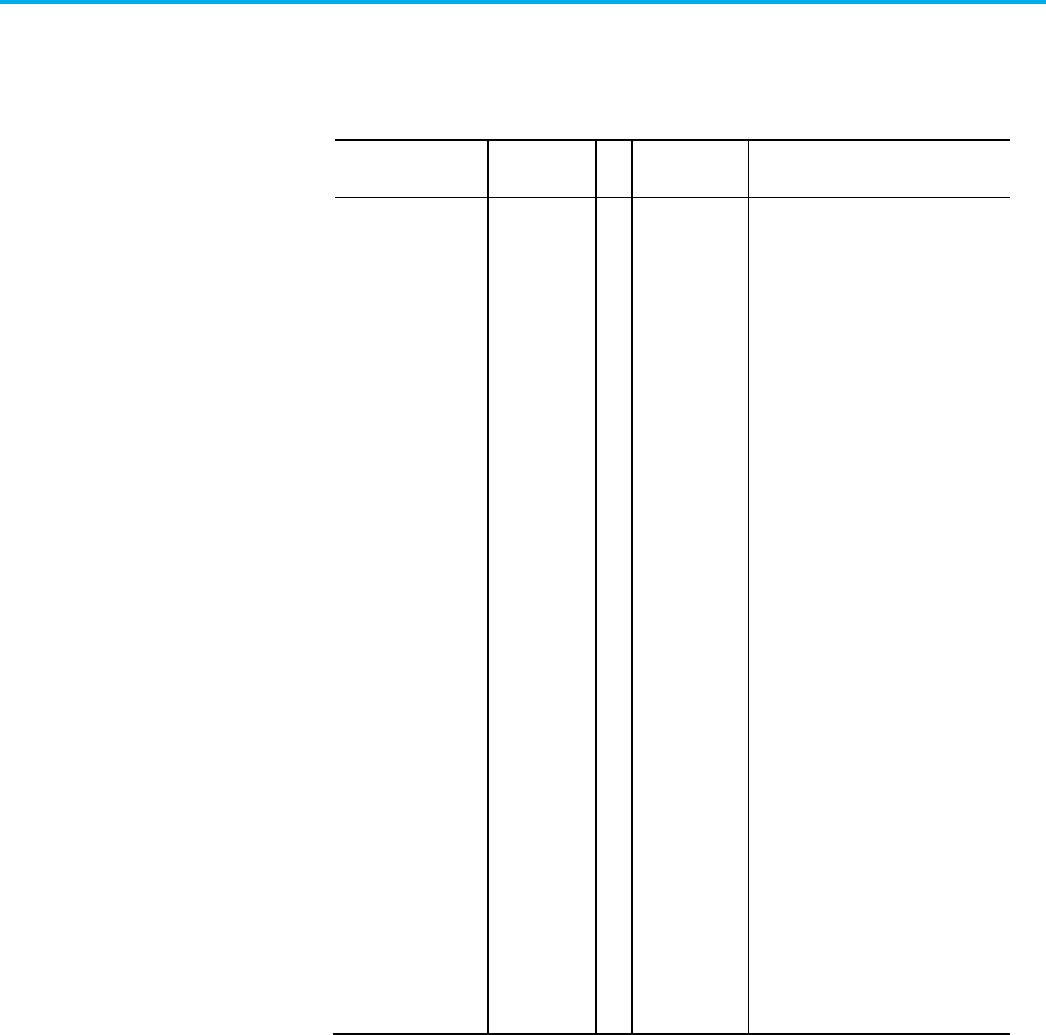
Chapter 4 CIP Axis Attributes
Rockwell Automation Publication MOTION-RM003O-EN-P - November 2023 661
Guard Status
Usage Access T Data Type Semantics of Values
Optional - D Get/GSV T DWORD Bitmap
0 = Guard OK
1 = Guard Config Locked
2 = Guard Gate Drive Output
3 = Guard Stop Input
4 = Guard Stop Request
5 = Guard Stop In Progress
6 = Guard Stop Decel
7 = Guard Stop Standstill
8 = Guard Stop Output
9 = Guard Limited Speed Input
10 = Guard Limited Speed Request
11 = Guard Limited Speed Monitor In
Progress
12 = Guard Limited Speed Output
13 = Guard Max Speed Monitor In
Progress
14 = Guard Max Accel Monitor In Progress
15 = Guard Direction Monitor In Progress
16 = Guard Door Control Lock
17 = Guard Door Control Output
18 = Guard Door Monitor Input
19 = Guard Door Monitor In Progress
20 = Guard Lock Monitor Input
21 = Guard Enabling Switch Input
22 = Guard Enabling Switch In Progress
23 = Guard Reset Input
24 = Guard Reset Required
25 = Guard Stop Input Cycle Required
26 = Reserved - Waiting for Stop Request
Removal
27...31 = Reserved
Collection of bits indicating the safety status of the motion axis.
Guard OK = indicates if the drive is free of any Guard Fault conditions.
Guard Config Locked = indicates that configuration data for the drive safety
core has been locked and cannot be modified.
Guard Gate Drive Output = indicates the state of the Gate Drive (MP OUT)
circuit used to disable the drive power structure.
Guard Stop Input = indicates the current state of the Safe Stop input.

Chapter 4 CIP Axis Attributes
662 Rockwell Automation Publication MOTION-RM003O-EN-P - November 2023
Guard Stop Request = indicates if a safe stop operation has been requested.
The safe stop request can be initiated by the Safe Stop Input or in response to
a Safety Fault. The bit is only cleared by a successful safety reset
Guard Stop In Progress = indicates if the Safe Stop (SS) function of the safety
core is in progress. This bit is set when the Safe Stop input transitions from
on to off and clears at the end of the stop delay or when a safety fault occurs.
Guard Stop Decel = indicates if the Safe Stop (SS) function of the safety core is
actively decelerating the axis. This bit is set after the monitoring delay expires
and clears at the end of the stop delay or when a fault occurs.
Guard Stop Standstill = indicates if the Safe Stop (SS) function of the safety
core is in the safe stopped mode, i.e. has successfully stopped the axis and is
performing zero speed monitoring. This bit is set after the stop delay expires
and clears when a fault occurs.
Guard Stop Output = indicates the current state of the Safe Stop output.
Guard Limited Speed Input = indicates the current state of the Safe Limited
Speed (SLS) input.
Guard Limited Speed Request = indicates if a safe speed operation has been
requested. The safe stop request can be initiated by the Safe Limited Speed
input. The bit is only cleared by a successful safety reset.
Guard Limited Speed Monitor In Progress = indicates if the Safe Speed
(SLS/SSM) monitoring function of the safety core is actively checking speed.
This bit is set when the Safe Limited Speed input transitions from on to off
and the associated monitoring delay has expired.
Guard Limited Speed Output = indicates the current state of the Safe Limited
Speed (SLS) output.
Guard Max Speed Monitor In Progress = indicates if the Safe Max Speed
(SMS) monitoring function of the safety core is in progress.
Guard Max Accel Monitor In Progress = indicates if the Safe Max Accel (SMA)
monitoring function of the safety core is in progress.
Guard Direction Monitor In Progress = indicates if the Safe Direction
Monitoring (SDM) function of the safety core is in progress. Guard Door
Output = indicates the current state of the Safe Door output.
Guard Door Control Lock = indicates if the Door Control Output is being
commanded to the Locked state.
Guard Door Control Output = indicates the current state of the Safe Door
Control output.
Guard Door Monitor Input = indicates the current state of the Door Monitor
(DM) input.

Chapter 4 CIP Axis Attributes
Rockwell Automation Publication MOTION-RM003O-EN-P - November 2023 663
Guard Door Monitor In Progress = indicates if the Safe Door Monitoring
(DM) function of the safety core is in progress.
Guard Lock Monitor Input = indicates the current state of the Safe Lock
Monitoring input.
Guard Enabling Switch Monitor Input = indicates the current state of the Safe
Enabling Switch Monitor input.
Guard Enabling Switch Monitor In Progress = indicates if the Safe Enabling
Switch Monitor (ESM) monitoring function of the safety core is in progress.
Guard Reset Input = indicates the state of the Safety Reset input use to initiate
return to normal operational state of the safety core.
Guard Reset Required = indicates that the drive’ safety function requires as
Safety Reset to permit return to normal operational state.
Guard Status Bit Descriptions
Bit
Name
Description
0 Guard OK Indicates if the drive is free of any Guard Fault conditions.
1 Guard Config Locked Indicates that configuration data for the drive safety core has
been locked and cannot be modified.
2 Guard Gate Drive Output Indicates the state of the Gate Drive (MP OUT) circuit used to
disable the drive power structure.
3 Guard Stop Input Indicates the current state of the Safe Stop input.
4 Guard Stop Request Indicates if a safe stop operation has been requested. The safe
stop request can be initiated by the Safe Stop Input or in
response to a Safety Fault. The bit is only cleared by a
successful safety reset.
5 Guard Stop In Progress Indicates if the Safe Stop (SS) function of the safety core is in
progress. This bit is set when the Safe Stop input transitions
from on to off and clears at the end of the stop delay or when a
safety fault occurs.
6 Guard Stop Decel Indicates if the Safe Stop (SS) function of the safety core is
actively decelerating the axis. This bit is set after the
monitoring delay expires and clears at the end of the stop delay
or when a fault occurs.
7 Guard Stop Standstill Indicates if the Safe Stop (SS) function of the safety core is in
the safe stopped mode, for example, when it has successfully
stopped the axis and is performing zero speed monitoring. This
bit is set after the stop delay expires and clears when a fault
occurs.
8 Guard Stop Output Indicates the current state of the Safe Stop output.
9 Guard Limited Speed Input Indicates the current state of the Safe Limited Speed (SLS)
input.
10 Guard Limited Speed Request Indicates if a safe speed operation has been requested. The
safe stop request can be initiated by the Safe Limited Speed
input. The bit is only cleared by a successful safety reset.

Chapter 4 CIP Axis Attributes
664 Rockwell Automation Publication MOTION-RM003O-EN-P - November 2023
Bit
Name
Description
11 Guard Limited Speed Monitor In
Progress
Indicates if the Safe Speed (SLS/SSM) monitoring function of
the safety core is actively checking speed. This bit is set when
the Safe Limited Speed input transitions from on to off and the
associated monitoring delay has expired.
12 Guard Limited Speed Output Indicates the current state of the Safe Limited Speed (SLS)
output.
13 Guard Max Speed Monitor In
Progress
Indicates if the Safe Max Speed (SMS) monitoring function of
the safety core is in progress.
14 Guard Max Accel Monitor In
Progress
Indicates if the Safe Max Accel (SMA) monitoring function of the
safety core is in progress.
15 Guard Direction Monitor In
Progress
Indicates if the Safe Direction Monitoring (SDM) function of the
safety core is in progress.
16 Guard Door Control Lock Indicates if the Door Control Output is being commanded to the
Locked state.
17 Guard Door Control Output Indicates the current state of the Safe Door Control output.
18 Guard Door Monitor Input Indicates the current state of the Door Monitor (DM) input.
19 Guard Door Monitor In Progress Indicates if the Safe Door Monitoring (DM) function of the safety
core is in progress.
20 Guard Lock Monitor Input Indicates the current state of the Safe Lock Monitoring input.
21 Guard Enabling Switch Input Indicates the current state of the Safe Enabling Switch Monitor
input.
22 Guard Enabling Switch Monitor In
Progress
Indicates if the Safe Enabling Switch Monitor (ESM) monitoring
function of the safety core is in progress.
23 Guard Reset Input Indicates the state of the Safety Reset input use to initiate
return to normal operational state of the safety core.
24
Guard Reset Required
Indicates that the drive safety function requires a Safety Reset
to permit return to normal operational state.
25
Guard Stop Input Cycle Required
Status
Indicates that the drive safety function requires a Stop Input
Cycle to permit return to normal operational state.
26
Reserved (Waiting for Stop
Request Removal)
27-31 Reserved

Chapter 4 CIP Axis Attributes
Rockwell Automation Publication MOTION-RM003O-EN-P - November 2023 665
Guard Faults
Usage
Access
T
Data Type
Semantics
Optional - D GSV T DWORD Bitmap
0 = (Reserved - Combined Faults)
1 = Guard Internal Fault
2 = Guard Configuration Fault
3 = Guard Gate Drive Fault
4 = Guard Reset Fault
5 = Guard Feedback 1 Fault
6 = Guard Feedback 2 Fault
7 = Guard Feedback Speed Compare Fault
8 = Guard Feedback Position Compare Fault
9 = Guard Stop Input Fault
10 = Guard Stop Output Fault
11 = Guard Stop Decel Fault
12 = Guard Stop Standstill Fault
13 = Guard Stop Motion Fault
14 = Guard Limited Speed Input Fault
15 = Guard Limited Speed Output Fault
16 = Guard Limited Speed Monitor Fault
17 = Guard Max Speed Monitor Fault
18 = Guard Max Accel Monitor Fault
19 = Guard Direction Monitor Fault
20 = Guard Door Monitor Input Fault
21 = Guard Door Monitor Fault
22 = Guard Door Control Output Fault
23 = Guard Lock Monitor Input Fault
24 = Guard Lock Monitor Fault
25 = Guard Enabling Switch Monitor Input Fault
26 = Guard Enabling Switch Monitor Fault
27 = Guard Feedback 1 Voltage Monitor Fault
28 = Guard Feedback 2 Voltage Monitor Fault
29 = Reserved (RLM Reset Fault)
30...31 = Reserved
The Guard Faults attribute is a collection of bits indicating the safety faults of
the drive axis. When a safety fault condition occurs the safety core processor
always requests a Safe Stop operation and notifies the drive controller to set
the appropriate Guard Faults bit. This bit remains latched even if the safety
fault condition is cleared in the safety core. A Fault Reset Request to the
associated axis clears the safety fault bits, but the bits set again immediately if
the underlying safety fault condition is still present.

Chapter 4 CIP Axis Attributes
666 Rockwell Automation Publication MOTION-RM003O-EN-P - November 2023
Guard Faults Bit Descriptions
Bit
Name
Description
0 Reserved - Combined Faults
1 Guard Internal Fault An internal fault has been detected by the Safety Core
hardware. This can includes safety processor faults,
inter-processor communications faults, safety power
supply faults, and gate drive circuitry.
2 Guard Configuration Fault The safety configuration data is invalid.
3 Guard Gate Drive Fault Indicates that the Gate Drive (MP OUT) circuit used to
disable the drive power structure has detected an error.
4 Guard Reset Fault The Safety Reset input was ON at power up.
5 Guard Feedback 1 Fault A problem has been detected with the feedback 1
device.
6 Guard Feedback 2 Fault A problem has been detected with the feedback 2
device.
7 Guard Feedback Speed Compare
Fault
A speed miss-compare was detected between the two
feedback devices.
8 Guard Feedback Position Compare
Fault
A position discrepancy was detected between the two
feedback devices.
9
Guard Stop Input Fault
A fault has been detected on the Safe Stop input(s).
10 Guard Stop Output Fault A fault has been detected on the Safe Stop cascading
outputs.
11 Guard Stop Decel Fault A speed fault was detected during the deceleration
monitoring.
12 Guard Stop Standstill Fault Zero speed was not detected by the end of the stop
delay.
13 Guard Stop Motion Fault Motion was detected after stop was detected and the
door unlocked.
14 Guard Limited Speed Input Fault A fault has been detected on the Safe Limited Speed
input(s).
15 Guard Limited Speed Output Fault A fault has been detected on the Safe Limited Speed
outputs.
16
Guard Limited Speed Monitor Fault
The Safe Limited Speed has been exceeded.
17
Guard Max Speed Monitor Fault
The Safe Maximum Speed has been exceeded.
18 Guard Max Accel Monitor Fault The Safe Maximum Acceleration has been exceeded.
19 Guard Direction Monitor Fault Motion in the restricted direction has been detected.
20 Guard Door Monitor Input Fault A fault has been detected on the Door Monitoring
input(s).
21 Guard Door Monitor Fault The Door Monitoring inputs were detected as OFF when
they should have been ON.
22 Guard Door Control Output Fault A fault has been detected on the Door Control outputs.
23
Guard Lock Monitor Input Fault
A fault has been detected on Lock Monitoring input(s).
24 Guard Lock Monitor Fault The Lock Monitoring Inputs were detected as OFF when
the Door should have been locked or the Lock
Monitoring Inputs were detected as ON when the Door
was opened.

Chapter 4 CIP Axis Attributes
Rockwell Automation Publication MOTION-RM003O-EN-P - November 2023 667
Bit
Name
Description
25 Guard Enabling Switch Monitor Input
Fault
A fault has been detected on the Enabling Switch
Monitor (ESM) input(s).
26 Guard Enabling Switch Monitor Fault The Enabling Switch Monitor (ESM) Inputs were detected
as OFF when they should have been ON.
27 Guard Feedback 1 Voltage Monitor
Fault
Monitored voltage level for the Feedback 1 device is out
of allowed range for operation.
28 Guard Feedback 2 Voltage Monitor
Fault
Monitored voltage level for the Feedback 2 device is out
of allowed range for operation.
29
Reserved (RLM Reset Fault)
30...31 Reserved
See also
Guard Safety Attributes on page 659
These are the drive safety attributes associated with a Motion Device Axis
Object.
Drive Safety Status
Usage
Access
T
Data
Type
Default
Min
Max
Semantics of Values
Drive Safety Attributes

Chapter 4 CIP Axis Attributes
668 Rockwell Automation Publication MOTION-RM003O-EN-P - November 2023
Usage
Access
T
Data
Type
Default
Min
Max
Semantics of Values
Optional - D Get T DWORD Bitmap:
0: Guard OK
1: Guard Config Locked
2: Guard Gate Drive Output
3: Guard Stop Input
4: Guard Stop Request
5: Guard Stop In Progress
6: Guard Stop Decel
7: Guard Stop Standstill
8: Guard Stop Output
9: Guard Limited Speed Input
10: Guard Limited Speed
Request
11: Guard Limited Speed
Monitor In Progress
12: Guard Limited Speed
Output
13: Guard Max Speed Monitor In
Progress
14: Guard Max Accel Monitor In
Progress
15: Guard Direction Monitor In
Progress
16: Guard Door Control Lock
17: Guard Door Control Output
18: Guard Door Monitor Input
19: Guard Door Monitor In
Progress
20: Guard Lock Monitor Input
21: Guard Enabling Switch
Input
Collection of bits indicating the safety status of the motion axis.
Guard OK = indicates if the drive is free of any Guard Fault conditions.
Guard Config Locked = indicates that configuration data for the drive safety
core has been locked and cannot be modified.
Guard Gate Drive Output = indicates the state of the Gate Drive (MP OUT)
circuit used to disable the drive power structure.
Guard Stop Input = indicates the current state of the Safe Stop input.
Guard Stop Request = indicates if a safe stop operation has been requested.
The safe stop request can be initiated by the Safe Stop Input or in response to
a Safety Fault. The bit is only cleared by a successful safety reset
Guard Stop In Progress = indicates if the Safe Stop (SS) function of the safety
core is in progress. This bit is set when the Safe Stop input transitions from
on to off and clears at the end of the stop delay or when a safety fault occurs.

Chapter 4 CIP Axis Attributes
Rockwell Automation Publication MOTION-RM003O-EN-P - November 2023 669
Guard Stop Decel = indicates if the Safe Stop (SS) function of the safety core is
actively decelerating the axis. This bit is set after the monitoring delay expires
and clears at the end of the stop delay or when a fault occurs.
Guard Stop Standstill = indicates if the Safe Stop (SS) function of the safety
core is in the safe stopped mode, i.e. has successfully stopped the axis and is
performing zero speed monitoring. This bit is set after the stop delay expires
and clears when a fault occurs.
Guard Stop Output = indicates the current state of the Safe Stop output.
Guard Limited Speed Input = indicates the current state of the Safe Limited
Speed (SLS) input.
Guard Limited Speed Request = indicates if a safe speed operation has been
requested. The safe stop request can be initiated by the Safe Limited Speed
input. The bit is only cleared by a successful safety reset.
Guard Limited Speed Monitor In Progress = indicates if the Safe Speed
(SLS/SSM) monitoring function of the safety core is actively checking speed.
This bit is set when the Safe Limited Speed input transitions from on to off
and the associated monitoring delay has expired.
Guard Limited Speed Output = indicates the current state of the Safe Limited
Speed (SLS) output.
Guard Max Speed Monitor In Progress = indicates if the Safe Max Speed
(SMS) monitoring function of the safety core is in progress.
Guard Max Accel Monitor In Progress = indicates if the Safe Max Accel (SMA)
monitoring function of the safety core is in progress.
Guard Direction Monitor In Progress = indicates if the Safe Direction
Monitoring (SDM) function of the safety core is in progress. Guard Door
Output = indicates the current state of the Safe Door output.
Guard Door Control Lock = indicates if the Door Control Output is being
commanded to the Locked state.
Guard Door Control Output = indicates the current state of the Safe Door
Control output.
Guard Door Monitor Input = indicates the current state of the Door Monitor
(DM) input.
Guard Door Monitor In Progress = indicates if the Safe Door Monitoring
(DM) function of the safety core is in progress.
Guard Lock Monitor Input = indicates the current state of the Safe Lock
Monitoring input.
Guard Enabling Switch Monitor Input = indicates the current state of the Safe
Enabling Switch Monitor input.

Chapter 4 CIP Axis Attributes
670 Rockwell Automation Publication MOTION-RM003O-EN-P - November 2023
Guard Enabling Switch Monitor In Progress = indicates if the Safe Enabling
Switch Monitor (ESM) monitoring function of the safety core is in progress.
Guard Reset Input = indicates the state of the Safety Reset input use to initiate
return to normal operational state of the safety core.
Guard Reset Required = indicates that the drive’ safety function requires as
Safety Reset to permit return to normal operational state.
Guard Stop Input Cycle Required = indicates that the drive’ safety function
requires as Safety Reset to permit return to normal operational state.

Chapter 4 CIP Axis Attributes
Rockwell Automation Publication MOTION-RM003O-EN-P - November 2023 671
Drive Safety Faults
Usage
Access
T
Data
Type
Default
Min
Max
Semantics of Values

Chapter 4 CIP Axis Attributes
672 Rockwell Automation Publication MOTION-RM003O-EN-P - November 2023
Usage
Access
T
Data
Type
Default
Min
Max
Semantics of Values
Optional - D Get T DWORD - - - Bitmap:
0: (Reserved– Combined
Faults)
1: Guard Internal Fault
2: Guard Configuration
Fault
3: Guard Gate Drive Fault
4: Guard Reset Fault
5: Guard Feedback 1
Fault
6: Guard Feedback 2
Fault
7: Guard Feedback
Speed Compare Fault
8: Guard Feedback
Position Compare Fault
9: Guard Stop Input Fault
10: Guard Stop Output
Fault
11: Guard Stop Decel
Fault
12: Guard Stop Standstill
Fault
13: Guard Stop Motion
Fault
14: Guard Limited Speed
Input Fault
15: Guard Limited Speed
Output Fault
16: Guard Limited Speed
Monitor Fault
17: Guard Max Speed
Monitor Fault
18: Guard Max Accel
Monitor Fault
19: Guard Direction
Monitor Fault
20: Guard Door Monitor
Input Fault
21: Guard Door Monitor
Fault
22: Guard Door Control
Output Fault
23: Guard Lock Monitor
Input Fault
24: Guard Lock Monitor
Fault
25: Guard Enabling
Switch Monitor Input
Fault
26: Guard Enabling
Switch Monitor Fault
27: Guard Feedback 1
Voltage Monitor Fault
28: Guard Feedback 2
Voltage Monitor Fault
29 : Reserved (RLM Reset

Chapter 4 CIP Axis Attributes
Rockwell Automation Publication MOTION-RM003O-EN-P - November 2023 673
Collection of bits indicating the safety fault status of the drive axis. When a
safety fault condition occurs the safety core processor always requests a Safe
Stop operation and notifies the drive controller to set the appropriate Guard
Faults bit. This bit shall remain latched even if the safety fault condition is
cleared in the safety core. A Fault Reset Request to the associated axis clears
the safety fault bits, but the bits sets again immediately if the underlying
safety fault condition is still present.
Guard Internal Fault = An internal fault has been detected by the Safety Core
hardware. This can includes safety processor faults, inter-processor
communications faults, safety power supply faults, and gate drive circuitry.
Guard Configuration Fault = The safety configuration data is invalid.
Guard Gate Drive Fault = Indicates that the Gate Drive (MP OUT) circuit used
to disable the drive power structure has detected an error.
Guard Reset Fault = The Safety Reset input was ON at power up.
Guard Feedback 1 Fault = A problem has been detected with the feedback 1
device.
Guard Feedback 2 Fault = A problem has been detected with the feedback 2
device.
Guard Feedback Speed Compare Fault = A speed miss-compare was detected
between the two feedback devices.
Guard Feedback Position Compare Fault = A position discrepancy was
detected between the two feedback devices.
Guard Stop Input Fault = A fault has been detected on the Safe Stop input(s).
Guard Stop Output Fault = A fault has been detected on the Safe Stop
cascading outputs.
Guard Stop Decel Fault = A speed fault was detected during the deceleration
monitoring.
Guard Stop Standstill Fault = Zero speed was not detected by the end of the
stop delay.
Guard Stop Motion Fault = Motion was detected after stop was detected and
the door unlocked.
Guard Limited Speed Input Fault = A fault has been detected on the Safe
Limited Speed input(s).
Guard Limited Speed Output Fault = A fault has been detected on the Safe
Limited Speed outputs(s).
Guard Limited Speed Monitor Fault = The Safe Limited Speed has been
exceeded.

Chapter 4 CIP Axis Attributes
674 Rockwell Automation Publication MOTION-RM003O-EN-P - November 2023
Guard Max Speed Monitor Fault = The Safe Maximum Speed has been
exceeded.
Guard Max Accel Monitor Fault = The Safe Maximum Acceleration has been
exceeded.
Guard Direction Monitor Fault = Motion in the restricted direction has been
detected.
Guard Door Monitor Input Fault = A fault has been detected on the Door
Monitoring input(s).
Guard Door Monitor Fault = The Door Monitoring inputs were detected as
OFF when they shall have been ON.
Guard Door Control Output Fault = A fault has been detected on the Door
Control outputs.
Guard Lock Monitor Input Fault = A fault has been detected on Lock
Monitoring input(s).
Guard Lock Monitor Fault = The Lock Monitoring Inputs were detected as
OFF when the Door shall have been locked or the Lock Monitoring Inputs
were detected as ON when the Door was opened.
Guard Enabling Switch Monitor Input Fault = A fault has been detected on the
Enabling Switch Monitor (ESM) input(s).
Guard Enabling Switch Monitor Fault = The Enabling Switch Monitor (ESM)
Inputs were detected as OFF when they shall have been ON.
Guard Feedback 1 Voltage Monitor Fault = monitored voltage level for the
Feedback 1 device is out of allowed range for operation.
Guard Feedback 2 Voltage Monitor Fault = monitored voltage level for the
Feedback 2 device is out of allowed range for operation.
See also
Drive Output Attributes on page 395
These are the active stopping and braking related attributes associated with a
Motion Control Axis.
AC Injection Brake Frequency Threshold
Usage
Access
Data
Type
Default
Min
Max
Semantics of Values
Optional - D (IM) Set/SSV REAL 1 0
Hz
Stopping and Braking
Attributes

Chapter 4 CIP Axis Attributes
Rockwell Automation Publication MOTION-RM003O-EN-P - November 2023 675
Value that sets the frequency that initiates the transition from AC injection
braking to DC injection braking when executing an “AC Injection Brake”
Stopping Action. When the output frequency drops below this threshold
during the braking operation, the transition from AC injection braking to DC
injection braking occurs.
AC Injection Brake Power Threshold
Usage
Access
Data
Type
Default
Min
Max
Semantics of Values
Optional - D (IM) Set/SSV REAL 1 0
%
Value that adjusts the drive’s internally defined power threshold that initiates
the transition from AC injection braking to DC injection braking when
executing an “AC Injection Brake” Stopping Action. When the output power
level drops below this threshold during the braking operation, the transition
from AC injection braking to DC injection braking occurs. A value of 100%
results in the drive using 100% of its internally defined power threshold when
checking for this transition condition.
AC Injection Brake Regulator Ki
Usage
Access
Data
Type
Default
Min
Max
Semantics of Values
Optional - D (IM) Set/SSV REAL 0.1 0
(Hz/Volt)/Sec
Value that sets the proportional gain of the regulator that controls the output
frequency applied to the motor based on the DC bus voltage when executing
an “AC Injection Brake” Stopping Action.
AC Injection Brake Regulator Kn
Usage
Access
Data
Type
Default
Min
Max
Semantics of Values
Optional - D (IM) Set/SSV REAL 0.1 0
Hz/Volt
Value that sets the proportional gain of the regulator that controls the output
frequency applied to the motor based on the DC bus voltage when executing
an “AC Injection Brake” Stopping Action.

Chapter 4 CIP Axis Attributes
676 Rockwell Automation Publication MOTION-RM003O-EN-P - November 2023

Chapter 4 CIP Axis Attributes
Rockwell Automation Publication MOTION-RM003O-EN-P - November 2023 677
Stopping Action
Usage
Access
Data
Type
Default
Min
Max
Semantics of Values
Required - XD Set/SSV# USINT Eq 23
1 for C
0 for F
0 for X
- - Enumeration:
0 = Disable & Coast
1 = Current Decel & Disable
2 = Ramped Decel & Disable
3 = Current Decel & Hold
4 = Ramped Decel & Hold
5-127 = (reserved)
128-255 = (vendor specific)
128 = DC Injection Brake
129 = AC Injection Brake
#
Indicates the attribute cannot be set while the tracking command (Tracking Command bit in CIP Axis
Status is true).
When disabling or aborting an axis, through a Disable Request or an Abort
Request this value determines the stopping method to apply to the motor.
Each supported Stopping Action initiates one of three Stopping Sequences
(IEC60204-1 Category Stops 0, 1, and 2).
• In the case of a Disable Request, the stopping method is applied while
in the Stopping state and the final state after the stopping method is
completed is the Stopped state.
• In the case of an Abort Request, the stopping method is applied while
in the Aborting state and the final state after the stopping method
completes is the Major Faulted state.
In either final state the device's inverter power structure will either be
Disabled (Disable selection) and free of torque or actively held (Hold selection)
in a static condition. This attribute has no impact or relationship to the
planner generated acceleration and deceleration profiles. This attribute does
not, in any way, determine the stopping actions applied in response to fault
conditions.
Connection Loss Stopping Action
Usage
Access
Data
Type
Default
Min
Max
Semantics of Values

Chapter 4 CIP Axis Attributes
678 Rockwell Automation Publication MOTION-RM003O-EN-P - November 2023
Usage
Access
Data
Type
Default
Min
Max
Semantics of Values
Optional - XD Set/SSV# USINT Eq 23
1 for C
0 for F
0 for X
- - 0 = Disable and Coast
1 = Current Decel and Disable
2 = Ramped Decel and Disable
3 = Current Decel and Hold
4 = Ramped Decel and Hold
5-127 = Reserved
128 = DC Injection Brake
129 = AC Injection Brake
130-255 = Vendor Specific
#
Indicates the attribute cannot be set while the tracking command (Tracking Command bit in CIP Axis
Status is true).
When a CIP Motion connection loss is detected, this value determines the
stopping method to apply to the motor. Each supported Stopping Action
initiates the associated Stopping Sequence (IEC60204-1 Category Stops 0, 1,
and 2). If the connection is closed intentionally using a Forward Close service,
the selected stopping method is applied while in the Stopping state and the
final state after the stopping method completes is the Initializing state. If the
connection is unintentionally lost and the resulting Node Fault generated
(Node Fault Codes 1 or 6), the selected stopping method is applied while in the
Aborting state and the final state after the stopping method completes is the
Major Faulted state. In either final state the device’s inverter power structure
will either be Disabled (Disable selection) and free of torque or actively held
(Hold selection) in a static condition.
Stopping Action Enumeration Definitions
Enum.
Usage
Name
Description
0 R/XD Disable and
Coast
Disable and Coast immediately disables the device power
structure and active control loops, which causes the motor to
coast unless some form of external braking is applied. This is
equivalent to an IEC-60204-1 Category 0 Stop.

Chapter 4 CIP Axis Attributes
Rockwell Automation Publication MOTION-RM003O-EN-P - November 2023 679
Enum.
Usage
Name
Description
1 R/C
O/XF
Current Decel
and Disable
Current Decel and Disable leaves the power structure and any
active control loops enabled while stopping.
If configured for position control mode, the drive forces the
position reference to hold its current value until the axis
reaches zero speed. Once at zero speed the position reference
is immediately set equal to the actual position to hold the axis
at standstill.
If in velocity control mode, the drive forces the velocity
reference to zero.
In either case, forcing the position or velocity reference signals
to a fixed value results in a rapid increase in control loop error
of the moving axis that saturates the output current of the
drive to the configured Stopping Torque that brings the motor
to a stop.
In torque control mode, the drive directly applies the configured
Stopping Torque to the torque command signal to decelerate
the motor. When the velocity feedback value reaches zero
speed, the torque command is set to zero.
Once stopped, or the configured Stopping Time or factory time
limit expires, the drive disables the power structure and control
loops. This stop mode complies with the IEC-60204-1 Category 1
Stop.
In frequency control mode the operative current limit, rather
than the Stopping Torque attribute, is used to regulate the
stopping current.
When applied to track sections, this stopping action leaves the
power structure enabled for the configured Stopping Time and
Mechanical Brake Engage Delay to allow time for movers local
to the section to be brought to a stop by their associated
remotes sections.
2 O/FV Ramped Decel
and Disable
Ramped Decel and Disable also leaves the power structure and
any active control loops enabled while stopping but uses the
Ramp Generator associated with the Velocity Fine Command
Generator block to decelerate the motor to a stop. When
initiating a Ramped Decel and Disable Stop, the Ramp
Generator is immediately activated and the drive no longer
follows command from the controller. The Ramp Generator
input is initialized to zero and the output is initialized to the
current speed of the motor, thus causing the Ramp Generator
output to ramp the motor from its current speed down to zero
according to the ramp control parameters. Once stopped, or the
configured Stopping Time or factory timeout limit expires, the
device disables the power structure and control loops. This stop
mode also complies with the IEC-60204-1 Category 1 Stop.
3
O/PV
Current Decel
and Hold
Current Decel and Hold behaves like Current Decel and Disable,
but leaves the power structure active with holding torque to
maintain the stopped condition. The method for generating
holding torque is left to the drive vendor's discretion. This stop
mode complies with the IEC-60204-1 Category 2 Stop.
The Current Decel and Hold stopping action is not allowed if a
Start Inhibit condition is present. If a Start Inhibit condition is
present, a Current Decel and Disable will be initiated instead.

Chapter 4 CIP Axis Attributes
680 Rockwell Automation Publication MOTION-RM003O-EN-P - November 2023
Enum.
Usage
Name
Description
4 O/V Ramped Decel
and Hold
Ramped Decel and Hold behaves like Ramped Decel and
Disable, but leaves the power structure with holding torque to
maintain the stopped condition. This stop modes also complies
with the IEC-60204-1 Category 2 Stop.
The Ramped Decel and Hold stopping action is not allowed if a
Start Inhibit condition is present. If a Start Inhibit condition is
present, a Ramped Decel and Disable will be initiated instead.
5-127 Reserved
128-255
Vendor Specific
128 O/D DC Injection
Brake
DC Injection Brake immediately applies the configured DC
Injection Brake Current to the motor to create a static flux field
to bring the motor to a stop before disabling the power
structure.
129 O/D AC Injection
Brake
AC Injection Brake decreases the device output frequency
according from its present value to zero at the rate determined
by the configured Deceleration Limit. Stopping action is
accomplished by lowering the output frequency below the
motor rotor speed where regeneration does not occur and
instead mechanical energy is dissipated in the motor as heat.
Stopping Torque
Usage
Access
Data
Type
Default
Min
Max
Semantics of Values
Required - C Set/SSV REAL 100
FD
0 10
3
% Motor Rated
When disabling or aborting an axis, this value determines the maximum
amount of torque producing current available to stop the motor when the
Stopping Action is set to Current Decel. If this attribute is not supported, the
drive device will use the configured Positive and Negative Peak Current
Limits.
Stopping Time Limit
Usage
Access
Data
Type
Default
Min
Max
Semantics of Values
Optional - XD Set/SSV REAL 1 0 10
3
Seconds
When disabling or aborting an axis, this parameter determines the maximum
amount of time the drive allows to reach zero speed as part of the Category 1
or Category 2 Stop sequence. Action taken by the drive once the time limit is
reached depends on the Stop Category. For a Category 1 Stop, the drive
continues to apply Stopping Torque while engaging the brake. For a Category
2 Stop the drive continues to apply Stopping Torque but does not engage the
brake. If Stopping Time Limit is not supported a factory set timeout may be
applied.

Chapter 4 CIP Axis Attributes
Rockwell Automation Publication MOTION-RM003O-EN-P - November 2023 681
Coasting Time Limit
Usage
Access
Data
Type
Default
Min
Max
Semantics of Values
Optional - XD Set/SSV REAL Eq 23
0
0 10
3
Seconds
When disabling or aborting an axis, this parameter determines the maximum
amount of time the drive allows to reach zero speed as part of the Category 0
"Disable and Coast" Stop sequence. Action taken by the drive if the time limit
is reached is to engage the brake and advance to the Stopped state. If this
attribute is not supported, the Coasting Time Limit applies the Stopping Time
Limit value. If Stopping Time Limit is not supported a factory set timeout may
be applied.
Resistive Brake Contact Delay
When an external resistive brake is used, an external contactor switches the
UVW motor leads from the inverter power structure to an energy dissipating
resistor to stop the motor. This switching does not occur instantaneously and
enabling the power structure too early can cause electrical arcing across the
contactor. To prevent this condition, the Resistive Brake Contact Delay can be
set to the maximum time that it takes to fully close the contactor across the
UVW motor lines so when the axis is enabled, the inverter power structure is
not enabled until after the Resistive Brake Contact Delay Time has expired.
Resistive Brake operation is only applicable to PM Motor types.
The following sequence further defines how the Resistive Brake Contact Delay
factors into the overall Enable Sequence that may also include the operation of
a Mechanical Brake. Note that the Resistive Brake Contact Delay and the
Mechanics Brake Release Delay attributes apply even if there is no external
contactor or mechanical brake connected to the drive.
Enable Sequence:
1. Switch to Starting state.
2. Activate Resistive Brake contactor to connect motor to inverter power
structure.
3. Wait for "Resistive Brake Contact Delay" while Resistive Brake contacts
close.
4. Enable inverter power structure.
5. (Optional) Perform Torque Proving operation to verify motor control
of load.
6. Activate Mechanical Brake output to release brake.
7. Wait for "Mechanical Brake Release Delay" while brake releases.
8. Transition to Running state.

Chapter 4 CIP Axis Attributes
682 Rockwell Automation Publication MOTION-RM003O-EN-P - November 2023
Mechanical Brake Control
Usage
Access
Data
Type
Default
Min
Max
Semantics of Values
Optional - D Set/SSV USINT 0 - - Enumeration
0 = Automatic
1 = Brake Release
2-225 = Reserved
The Mechanical Brake Control attribute governs the operation of the
Mechanical Brake Output of the drive. The Mechanical Brake Output controls
the mechanical brake mechanism. When set to Automatic, the Mechanical
Brake is under the control of the axis state machine. The Mechanical Brake
Engage Delay and Mechanical Brake Release Delay attributes describe the
sequencing for the brake. To release the brake, set the brake to Brake Release.
The axis state machine releases control of the brake.
Mechanical Brake Release Delay
When enabling the axis with an engaged mechanical brake, the Mechanical
Brake Release Delay value determines the amount of time the drive shall delay
transition from the Starting state to the Running or Testing states. This delay
prevents any commanded motion until the external mechanical brake has had
enough time to disengage. If supported, a Torque Proving operation is
included in this sequence prior to releasing the brake. Note that the Resistive
Brake Contact Delay and the Mechanical Brake Release Delay attributes apply
even if there is no external contactor or mechanical brake connected to the
drive.
Enable Sequence:
1. Switch to Starting state.
2. Activate Resistive Brake contactor to connect motor to inverter power
structure.
3. Wait for "Resistive Brake Contact Delay" while Resistive Brake contacts
close.
4. Enable inverter power structure.
5. (Optional) Perform Torque Proving operation to verify motor control
of load.
6. Activate Mechanical Brake output to release brake.
7. Wait for "Mechanical Brake Release Delay" while brake releases.
8. Transition to Running (or Testing) state.
Mechanical Brake Engage Delay
Usage
Access
Data
Type
Default
Min
Max
Semantics of Values

Chapter 4 CIP Axis Attributes
Rockwell Automation Publication MOTION-RM003O-EN-P - November 2023 683
Usage
Access
Data
Type
Default
Min
Max
Semantics of Values
Optional - XD Set/SSV REAL Eq 23
0
0 10
3
Seconds
When disabling the motion axis using a Category 1 Stopping Action, the
Mechanical Brake Engage Delay value determines the amount of time the
device power structure will remain enabled after the axis has decelerated to
standstill. This attribute allows time for an external mechanical brake to
engage. The configured Stopping Action determines the type of stopping
sequence applied. If supported, a Brake Proving operation is included in the
Category 1 stopping sequence prior to disabling the power structure. Note
that the Mechanical Brake Release Delay attribute applies even if there is
mechanical brake connected to the drive.
Zero Speed
Usage
Access
Data
Type
Default
Min
Max
Semantics of Values
Optional - D Set/SSV REAL 1
FD
0
% Motor Rated
This attribute sets the speed threshold associated with the zero speed criteria
of the stop sequence. Zero Speed is specified as a percent of motor rated
speed. When Zero Speed Time attribute is supported, this attribute sets the
speed threshold where the zero speed timer starts. When the axis speed has
been below the Zero Speed threshold for Zero Speed Time the axis has
satisfied the zero speed criteria. In all but Category 2 stops, this results in
action to engage the mechanical brake. If this attribute is not supported, the
zero speed threshold is left to the vendor’s discretion and typically set to 1% of
motor rated speed. Axis speed in the above description is based on the
Velocity Feedback signal, or in the case of a Frequency Control drive, axis
speed is based on Velocity Reference signal.
When supporting a Load Observer, the zero speed criteria is not based on the
Velocity Estimate since that signal can differ considerably from the actual
speed of the motor. When the Load Observer is configured to apply the
Velocity Estimate to the velocity loop summing junction as Velocity Feedback,
the zero speed criteria must be based on the velocity feedback signal input to
the Load Observer.
Zero Speed Time
Usage
Access
Data
Type
Default
Min
Max
Semantics of Values
Optional - D Set/SSV REAL 0 0 10
3
Sec

Chapter 4 CIP Axis Attributes
684 Rockwell Automation Publication MOTION-RM003O-EN-P - November 2023
This attribute sets the amount of time that the axis speed must be below the
zero speed threshold, set by the Zero Speed attribute or established by the
drive vendor, before satisfying the zero speed criteria. In all but Category 2
stops, when this attribute is set it results in action to engage the mechanical
brake. If this attribute is not supported, the amount of time needed to satisfy
the zero speed criteria is left to the vendor’s discretion and typically is
immediate (0). Axis speed in the above description is based on the Velocity
Feedback signal, or in the case of a Frequency Control drive, axis speed is
based on Velocity Reference signal.
When supporting a Load Observer, the zero speed criteria is not based on the
Velocity Estimate since that signal can differ considerably from the actual
speed of the motor. When the Load Observer is configured to apply the
Velocity Estimate to the velocity loop summing junction as Velocity Feedback,
the zero speed criteria must be based on the velocity feedback signal input to
the Load Observer.
Vertical Load Control
Usage
Access
Data
Type
Default
Min
Max
Semantics of Values
Optional - FPV Set/GSV USINT 0 - - Enumeration:
0 = Disabled
1 = Enabled
2 - 255 = Reserved
This enumerated value allows the drive to tailor motor control behavior for
vertical load applications. When the Enabled enumeration is selected, the
drive attempts, whenever possible, to avoid applying Category 0 stop actions
in response to Major Fault conditions. The drive may tailor other aspects of its
behavior to best handle vertical loads.
Proving Configuration
Usage
Access
Data
Type
Default
Min
Max
Semantics of Values
Optional - D Set/SSV USINT 0
FD
- - Enumeration:
0 = Disabled
1 = Enabled
2 - 255 = Reserved
This attribute enables the operation of the drive's Torque Proving and Brake
Proving functions that work in conjunction with mechanical brake control.
When Proving is enabled, the mechanical brake must be set as soon as the
drive is disabled. When the brake is under the control of the axis state
machine this is automatic. But when controlled externally, failure to set the
brake when the drive is disabled can cause a free fall condition on a vertical
application.

Chapter 4 CIP Axis Attributes
Rockwell Automation Publication MOTION-RM003O-EN-P - November 2023 685
When enabled, the drive performs a Torque Prove test of the motor current
while in the Starting state to "prove" that current is properly flowing through
each of the motor phases before releasing the brake. Should the Torque Prove
test fail, a Motor Phase Loss exception is generated.
While Torque Proving functionality is applicable to drive Control Modes that
are not capable of generating reliable holding torque based on a feedback
device, such as Frequency Control and Sensorless Velocity Control, Torque
Proving should not be used in these modes for applications where holding
torque is critical to safe operation, such as in a typical lift or crane application.
If the optional Brake Test Torque attribute is supported, the Torque Prove test
also includes a proactive Brake Test to ensure the mechanical brake is
functioning properly. Should the Brake Test detect brake slip, a Brake Slip
exception is generated.
When Proving is enabled, the drive also performs a Brake Prove test while in
the Stopping or Aborting states to "prove" proper mechanical brake function
before the drive power structure is disabled. Should the Brake Prove test
detect brake slip a Brake Slip exception is generated.
Unless another vendor specific method is used to address a Brake Slip
condition in the Stopping or Aborting state, the appropriate Fault Action for
the Brake Slip exception is Torque Limited Stop and Hold. This Fault Action
applies holding torque to arrest the brake slip and transitions the axis to the
Major Faulted state.
In general, Brake Proving functionality is only applicable to drive Control
Modes that are capable of generating holding torque based on a feedback
device. Brake Proving is therefore not applicable to Frequency Control or
Sensorless Velocity Control modes.
When Proving is enabled, and the Auto-Sag feature is supported, upon
detection of a brake slip condition, the drive has the capability of safely
lowering the load to the ground in a controlled series of increments. The Auto
Sag Configuration attribute is used to enable this feature. In addition to Brake
Slip initiating a Brake Slip exception, the drive also generates a Brake
Malfunction start inhibit when the Auto Sag feature is enabled.
When Proving, Auto Sag, and Auto Sag Start are all enabled, the drive also
monitors for brake slip in the Stopped or Faulted states. If brake slip is
detected, the drive power structure is automatically started to arrest the slip
allowing the Auto Sag function to safely lower the load to the ground. Upon
detection of brake slip, a Brake Slip exception is generated along with a Brake
Malfunction start inhibit.
The sequencing of the torque and brake "prove" tests are described in detail by
the Mechanical Brake Engage Delay and Mechanical Brake Release Delay
attributes.

Chapter 4 CIP Axis Attributes
686 Rockwell Automation Publication MOTION-RM003O-EN-P - November 2023
The Proving feature includes a number of optional Sub-Features, many of
which depend on support of other Proving feature attributes. The following
table defines these attribute dependencies.
Proving Sub-Feature
Controlling Attributes
Attribute Prerequisites
Torque Prove
Torque Prove Current
Proving Configuration
Brake Test Brake Test Torque
Brake Slip Tolerance
Proving Configuration
Brake Prove Brake Prove Ramp Time
Brake Slip Tolerance
Proving Configuration
Auto Sag
Auto Sag Configuration
Auto Sag Slip Increment
Proving Configuration
Brake Prove Ramp Time
Brake Slip Tolerance
Auto Sag Start Auto Sag Start Proving Configuration
Brake Prove Ramp Time
Brake Slip Tolerance
Auto Sag Configuration
Auto Sag Slip Tolerance
Proving tests are performed when enabling or disabling the drive axis. During
these state transitions a series of operations are performed by the drive to
ensure the proper function of the motor (Torque Proving) and the brake
(Brake Proving).
Torque Prove Current
Usage Access Data
Type
Default Min Max Semantics of Values
Optional - D Set/SSV REAL 0
FD
0 10
3
% Motor Rated
This attribute sets the percent of motor rated torque applied to the motor by
the Torque Prove test as part of the Torque Proving function executed in the
Starting state. The Torque Prove test applies current to the motor to "prove"
that current is properly flowing through each of the motor phases before
releasing the brake.
Brake Test Torque
Usage
Access
Data
Type
Default
Min
Max
Semantics of Values
Optional - DE Set/SSV REAL 0
FD
0 10
3
% Motor Rated
This attribute sets the percent of motor rated torque applied to the motor by
the Brake Test as part of the Torque Proving function executed in the Starting
state. This Brake Test proactively tests the ability of the mechanical brake to
hold the maximum anticipated load before releasing the brake and allowing
operation. Should the Brake Test detect brake slip, a Brake Slip exception is
generated.

Chapter 4 CIP Axis Attributes
Rockwell Automation Publication MOTION-RM003O-EN-P - November 2023 687
If the Brake Test Torque attribute value is 0 the Brake Test is not performed in
the Starting state.
Brake Prove Ramp Time
Usage
Access
Data
Type
Default
Min
Max
Semantics of Values
Optional - DE Set/SSV REAL 0
FD
0 10
3
Seconds
This attribute determines the amount of time the drive will take to ramp the
applied torque of the motor down to zero during the Brake Proving test in the
Stopping or Aborting state. The Brake Prove Ramp Time determines the ramp
down rate of the applied torque output by dividing the Torque Limit by the
Brake Prove Ramp Time. The Torque Limit in this case is the maximum of the
configured Torque Limit Positive and Torque Limit Negative values. The
Brake Prove test is performed to check for brake slip before the power
structure is disabled.
Brake Slip Tolerance
Usage
Access
Data
Type
Default
Min
Max
Semantics of Values
Optional - DE Set/SSV REAL 0
FD
0
Position Units
This attribute determines the amount of brake slip allowed after the brake is
engaged. If this tolerance is exceeded while the brake is engaged, a Brake Slip
exception is generated. Brake slip can therefore be monitored in any axis state
where the brake is engaged.
DC Injection Brake Current
Usage
Access
Data
Type
Default
Min
Max
Semantics of Values
Optional - D Set/SSV REAL 0 0 10
3
% Motor Rated
The DC Injection Brake Current attribute defines the brake current level
injected into an induction motor stator when DC Injection Brake is selected as
the Stopping Action. This attribute is specified as a percent of motor rated
speed.
DC Injection Brake Time
Usage
Access
Data
Type
Default
Min
Max
Semantics of Values
Optional - D Set/SSV REAL 0 0 10
3
Seconds

Chapter 4 CIP Axis Attributes
688 Rockwell Automation Publication MOTION-RM003O-EN-P - November 2023
The DC Injection Brake Time attribute defines the amount of time that the DC
brake current is injected into an induction motor stator when DC Injection
Brake is selected as the Stopping Action. This attribute is specified in seconds.
Flux Braking Enable
Usage
Access
Data
Type
Default
Min
Max
Semantics of Values
Optional - D
(IM)
Set/SSV USINT 0 - - 0 = Flux Braking Disabled
1 = Flux Braking Enabled
The Flux Braking Enable attribute value determines if the drive device is to
apply additional flux current to the induction motor in an effort to increase
motor losses and reduce the deceleration time while in the Stopping state.
This feature is useful when there is no Shunt Regulator or Regenerative Brake
available.
Auto Sag Configuration
Usage Access Data
Type
Default Min Max Semantics of Values
Optional - DE
Set/SSV
USINT
0
-
-
Enumeration:
0 = Disabled
1 = Enabled
2-255 = (reserved)
This attribute is used to enable the optional Auto Sag feature that, in the event
of detected a brake slip condition, safely lowers the load to the floor in a series
of controlled Auto Sag Slip Increments. When a brake slip condition is
detected and Auto Sag is enabled, the drive not only sets the standard Brake
Slip exception, but the drive also sets the Brake Malfunction start inhibit. This
prevents the drive from restarting after the load has been safely lowered to the
floor.
Auto Sag Slip Increment
Usage
Access
Data
Type
Default
Min
Max
Semantics of Values
Optional - DE Set/SSV REAL 0 0
Position Units
This attribute sets the incremental amount of brake slip allowed by the drive's
optional Auto Sag function before restoring holding torque. When brake slip
occurs, the drive allows this amount of displacement and then automatically
enables the power structure and applies holding torque to arrest the slip. The
drive then ramps the motor torque to zero based on the Brake Prove Ramp
Time while checking for slip. Should brake slip continue, the cycle repeats. In

Chapter 4 CIP Axis Attributes
Rockwell Automation Publication MOTION-RM003O-EN-P - November 2023 689
crane and lift applications, this repeating "Auto Sag" cycle is designed to lower
the load in a controlled series of Auto Sag Slip Increments until the load
reaches the ground.
Auto Sag Time Limit
Usage
Access
Data
Type
Default
Min
Max
Semantics of Values
Optional - DE Set/SSV REAL 0.25 0
Seconds
This attribute sets the time limit over which the drive checks for brake slip as
performed by the Auto Sag function before restoring holding torque. When
brake slip occurs, the drive allows this amount of time before automatically
enabling the power structure and applying holding torque. The drive then
ramps the motor torque to zero based on the Brake Prove Ramp Time while
checking for slip. Generally, in a brake slip situation, the Auto Sag Slip Time
Limit expires when the load reaches the ground after one or more Auto Sag
Slip Increment cycles. With no further slip occurring while the motor torque
is ramping to zero, the Auto Sag feature transitions the axis to the Major
Faulted state and the drive power structure is disabled.
The optional Auto Sag Slip Time Limit attribute is not required by the Auto
Sag feature. If not supported, a vendor specific value for the Auto Sag Slip
Time is applied, typically 0.25 seconds.
Auto Sag Start
Usage
Access
Data
Type
Default
Min
Max
Semantics of Values
Optional - DE Set/SSV USINT 0 - - Enumeration:
0 = Disabled
1 = Enabled
2-255 = (reserved)
When the Auto Sag Configuration attribute is set to Enabled, this attribute is
used to enable the Auto Sag function in the Stopped or Faulted state. When
Auto Sag Start is enabled, the drive monitors the load for possible brake slip
and should the amount of brake slip exceed the Brake Slip Tolerance a Brake
Slip exception is generated, along with a Brake Malfunction start inhibit.
When this occurs, the drive power structure is enabled (Started) without
holding torque and the axis transitions to the Aborting State. The drive
continues to monitor brake slip and when the amount of slip exceeds the Auto
Sag Slip Increment holding torque is applied to the motor to arrest the brake
slip. The drive then ramps the motor torque to zero based on the Brake Prove
Ramp Time while again checking for slip. Should brake slip continue and
exceed the Auto Sag Slip Increment, holding torque is applied and the cycle

Chapter 4 CIP Axis Attributes
690 Rockwell Automation Publication MOTION-RM003O-EN-P - November 2023
repeats. In crane and lift applications, this repeating "Auto Sag" cycle is
designed to lower the load in a controlled series of Auto Sag Slip Increments
until the load reaches the ground.
See also
Stopping Sequences on page 690
Proving Operation Sequences on page 693
State Behavior on page 74
Motor Attributes on page 69
CIP Axis Attributes on page 261
There are three different stopping sequences defined for stopping and
braking related attributes. These three stopping sequences align with the
following IEC-60204-1 Stop Categories:
• Category 0 Stop: Drive immediately disables inverter power structure.
• Category 1 Stop: Drive decelerates motor to a stop and then disables
power structure.
• Category 2 Stop: Drive decelerates motor to a stop and then applies
holding torque.
All actions initiated by the control or the drive to stop the axis or disable its
associated inverter power structure must execute one of these three stopping
sequences. Category 0 and Category 1 Stop sequences coordinate the
disabling of the drive power structure with brake operation and in some cases,
optional Brake Proving functionality.
The above stopping sequences are listed in order of precedence should a
stopping sequence be initiated while another stopping sequence is in
progress. For example, a Category 0 stopping sequence shall preempt a
Category 1 stopping sequence in progress, but a Category 1 stopping sequence
shall not supersede a Category 0 stopping sequence in progress. This rule of
precedence holds true regardless of the source that initiated the stopping
sequence.
The following stopping sequences are defined in the context of a Disable
Request generated stop, where the stopping methods are applied in the
Stopping state and the stopping sequences ends up in the Stopped state. In
the context of a Major Fault action, these same stopping methods are applied
in the Aborting state and the stopping sequences end up in the Major Faulted
state. In the context of a Shutdown Request, the Category 0 stopping method
below is applied in the Stopping state and the stopping sequence ends up in
Shutdown state.
Stopping Sequences

Chapter 4 CIP Axis Attributes
Rockwell Automation Publication MOTION-RM003O-EN-P - November 2023 691
Category 0 Stop Sequence
Inverter is immediately disabled. Brake Proving is not applicable.
1. Switch to Stopping state
2. Disable inverter power structure.
3. Deactivate Resistive Brake contactor to connect motor to brake
resistor, if applicable.
4. Wait for zero speed or "Coasting Time Limit" or a factory set timeout,
whichever occurs first.
5. Transition to Stopped state.
6. Deactivate Mechanical Brake output to engage brake, if applicable.
The following diagram illustrates Category 0 Stop Sequence:
Category 1 Stop Sequence
Torque applied to stop the motor before the inverter is disabled. Brake
Proving is applicable.
1. Switch to Stopping state.
2. Apply "Current Decel" or "Ramp Decel" method to stop motor.
3. Wait for zero speed or 'Stopping Time Limit' or a factory set timeout,
whichever occurs first.
4. Deactivate Mechanical Brake output to engage brake.
5. Wait for "Mechanical Brake Engage Delay" while brake engages.
6. Perform (optional) Brake Proving operation to verify brake control of
load.
7. Disable inverter power structure.
8. Transition to Stopped state.
9. Deactivate Resistive Brake contactor to disconnect motor from
inverter power structure.
The following diagram illustrates a Category 1 Stop Sequence:

Chapter 4 CIP Axis Attributes
692 Rockwell Automation Publication MOTION-RM003O-EN-P - November 2023
Category 2 Stop Sequence
Torque is applied to stop the motor and inverter is left enabled to provide
holding torque. The mechanical brake is not used. Brake Proving is not
applicable. A Category 2 Stop is only allowed in no Start Inhibit condition is
present.
1. Switch to Stopping state.
2. Apply "Current Decel" or "Ramp Decel" method to stop motor.
3. Wait for zero speed or "Stopping Time Limit" or a factory set timeout,
whichever occurs first.
4. Transition to Stopped state.
A Category 2 stop sequence is not allowed if initiated by a Disable Request or
fault action with a Start Inhibit condition present. If a Start Inhibit condition
is present, a Category 1 stop sequence is initiated instead, using the same
stopping method (Current Decel or Ramped Decel) that would have been
applied by the Category 2 stop sequence. Category 2 stop sequences are also
not allowed if initiated by a Start Inhibit condition with the axis in the
Stopped state or Major Faulted state with Holding torque. In this case, the
drive initiates a Category 1 stop sequence instead, using the same stopping
method (Current Decel or Ramped Decel) that would have been applied by the
configured Category 2 Stopping Action.
The following diagram illustrates a Category 2 Stop Sequence:

Chapter 4 CIP Axis Attributes
Rockwell Automation Publication MOTION-RM003O-EN-P - November 2023 693
Tip:
Recommended criteria for Zero Speed is based on Velocity Feedback, or in
the case of Frequency Control drive, based on Velocity Reference. Zero
Speed criteria can be established explicitly through optional Zero Speed and
Zero Speed Time attributes or implicitly as 1% of motor rated speed or left
to the drive vendor’s discretion.
See also
Stopping and Braking Attributes on page 674
Proving tests are performed when enabling or disabling the drive axis.
During these state transitions a series of operations are performed by the
drive to ensure the proper function of the motor (Torque Proving) and the
brake (Brake Proving).
The following flow charts define these operational sequences in the context of
a drive enable transition and a drive disable or abort transition.
Proving Operational
Sequences

Chapter 4 CIP Axis Attributes
694 Rockwell Automation Publication MOTION-RM003O-EN-P - November 2023
Drive Enable Sequence with Proving Tests

Chapter 4 CIP Axis Attributes
Rockwell Automation Publication MOTION-RM003O-EN-P - November 2023 695
Drive Disable Sequence with Proving Test
See also
Stopping and Braking Attributes on page 674
Stopping Sequences on page 690
These are the Start Inhibit related attributes associated with a Motion Control
Axis Object instance. Start Inhibits are conditions that prevent transition of
Start Inhibits Attributes
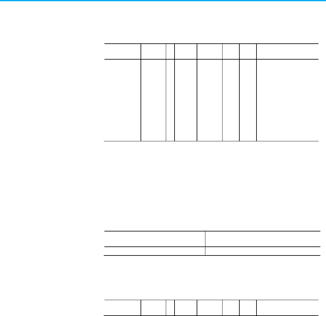
Chapter 4 CIP Axis Attributes
696 Rockwell Automation Publication MOTION-RM003O-EN-P - November 2023
the axis from the Stopped State into any of the operational states.
CIP Start Inhibits
Usage Access T Data
Type
Default Min Max Semantics of Values
Required - All Get/GSV T WORD - - - Enumeration:
0 = Reserved
1 = Axis Enable Input
2 = Motor Not Configured
3 = Feedback Not Configured
4 = Commutation Not
Configured
5 = Safe Torque Off Active
6 = Converter Bus Unload
7 - 15 = Reserved
A bit map that specifies the current state of all standard conditions that
inhibits starting of the axis.
Axis Test Mode
Axes with the Test Mode attribute set to Enabled and that are configured for
Controller Loop Back simulate these enumerated values for the CIP Start
Inhibit attribute.
Enumeration
Axis Test Mode
(Test Mode Configuration)
5 = Safe Torque Off Active
Controller Loop Back: V36
CIP Start Inhibits - RA
Usage
Access
T
Data
Type
Default
Min
Max
Semantics of Values

Chapter 4 CIP Axis Attributes
Rockwell Automation Publication MOTION-RM003O-EN-P - November 2023 697
Usage
Access
T
Data
Type
Default
Min
Max
Semantics of Values
Required - All Get/GSV T WORD - - - Enumeration:
0 = Reserved
1 = Volts Hertz Curve Definition
2 = Motor Feedback Required
3 = Speed Limit Configuration
4 = Torque Prove
Configuration
5 = Safe Torque Off
6 = Safety Reset Required
7 = Safety Not Configured
8 = Stop Command Active
9 = Feedback Device Reset
10 = Brake Malfunction
11 = AC Line Contactor Input
12 - 15 = Reserved
A bit map that specifies the current state of all Rockwell Automation specific
conditions that inhibits starting of the axis.
See also
Standard Start Inhibits on page 697
Rockwell Automation Specific Start Inhibits on page 698
CIP Axis Attributes on page 261
This table defines the list of standard start inhibits associated with the Start
Inhibits attribute.
Bit
Inhibit Condition
Description
0 -- Reserved -- This bit cannot be used since the Start Inhibit Code is defined by
the associated bit number and Start Inhibit Code of 0 means no
fault condition is present.
1 Axis Enable Input The Enable Input is not active.
2 Motor Not Configured The associated motor has not been configured for use.
3 Feedback Not Configured The associated feedback device has not been configured. The
offending feedback channel is encoded in the associated
Fault/Alarm Sub Code.
4 Commutation Not Configured The associated PM motor commutation function has not been
configured for use.
5 Safe Torque Off Active The integrated Safe Torque Off safety function is active based on
the Safe Torque Off Active bit (bit 3) of the Axis Safety Status
attribute being set.
6 Converter Bus Unload The Converter Bus Unload bit (bit 3) of the Control Status attribute
from the controller is set, indicating that the converter supplying
power to this drive axis has requested that it not draw power from
the DC Bus.
7 Bus Input Overcurrent The DC Bus Input Current exceeds the factory set limit given by the
Bus Input Overcurrent Factory Limit.
Standard Start Inhibits

Chapter 4 CIP Axis Attributes
698 Rockwell Automation Publication MOTION-RM003O-EN-P - November 2023
Bit
Inhibit Condition
Description
8 Invalid Slip Speed The configured Induction Motor Rated Slip Speed is less than or
equal to zero.
15
--Reserved--
This table maps the Standard Start Inhibit bits with their Logix Designer Start
Inhibit tag names. Start Inhibit bit names always end with an Inhibit suffix.
Bit Tag
0 NA
1 AxisEnableInputInhibit
2 MotorNotConfiguredInhibit
3
FeedbackNotConfiguredInhibit
4 CommutationNotConfiguredInhibit
5 SafeTorqueOffActiveInhibit
6 ConverterBusUnload
7 Bus Input Overcurrent Inhibit
8 Invalid Slip Speed Inhibit
See also
Start Inhibit Attributes on page 695
Rockwell Automation Specific Start Inhibits on page 698
Axis Safety Status Attributes on page 641
The following table defines a list of standard start inhibits associated with the
Start Inhibits attribute.
Bit
Inhibit Condition
Description
0 -- Reserved -- No fault condition is present.
1 Volts Hertz Curve
Definition
Conflict exists in the V/Hz curve definition.
2 Motor Feedback
Required
Cannot run using the selected motor control mode with Primary Feedback
or Alternate Feedback set as open loop.
3 Speed Limit
Configuration
Speed Ref Limit Conflict, either Minimum Forward Speed Limit exceeds
Maximum Forward Speed Limit, or Minimum Reverse Speed Limit exceeds
Maximum Reverse Speed Limit.
4 Torque Prove
Configuration
When Torque Prove Configuration is enabled, Control Mode, Feedback Mode,
Motor Feedback Type and Motor Option Configuration must be properly set.
5 Safe Torque Off The safety function has disabled the power structure.
6 Safety Reset
Required
The safety reset input needs to be toggled before the safety board will allow
motion again.
7 Safety Not
Configured
The embedded safety function of the drive has not been configured.
Rockwell Automation
Specific Start Inhibits

Chapter 4 CIP Axis Attributes
Rockwell Automation Publication MOTION-RM003O-EN-P - November 2023 699
Bit
Inhibit Condition
Description
8 Stop Command
Active
There is an active Stop Command present. For example, the Stop button on
the drive is behind held active. This inhibit condition prevents the drive
from starting when the Stop Command is active.
9 Feedback Device
Reset
The feedback device is being reset. A feedback device reset process is
typically performed after a Feedback Loss condition. This inhibit condition
prevents the drive from Starting until the feedback reset process is
completed.
10 Brake Malfunction The start inhibit is set when the Auto Sag function is enabled, and the brake
slip is detected based on motor movement exceeding the configured Brake
Slip Tolerance while the mechanical brake is engaged. This typically
indicates that the mechanical brake may not be capable of holding the load.
11 AC Line Contactor
Input
The start inhibit is set when state of the AC Line Contactor OK digital input
differs from the state of Contactor Enable Digital Output. When this start
inhibit is set it generally indicates that AC Line Contactor is not working
correctly and is not capable of charging the dc bus. This start inhibit is
checked only when a digital input is configured for the AC Line Contactor
OK function.
12 Track Section Not
Enabled
This start inhibit is set on a track cart or mover axis when the track section
axes associated with the current position of this cart or mover are not in
the Running state and therefore cannot apply force to this cart or mover..
13 Track Mover Motor
Mismatch
There is a track-wide mismatch in mover motor configuration.
14-15 --Reserved--
This table maps the Start Inhibit bits with their Logix Designer Start Inhibit
tag names. Start Inhibit bit names always end with an Inhibit suffix.
Bit Tag
0 -
1 VoltsHertzCurveDefinitionInhibit
2 MotorFeedbackRequiredInhibit
3
SpeedLimitConfigurationInhibit
4 TorqueProveConfigurationInhibit
5 SafeTorqueOffInhibit
6 SafetyResetRequiredInhibit
7 SafetyNotConfiguredInhibit
8
StopCommandActiveInhibit
9
FeedbackDeviceResetInhibit
10
BrakeMalfunctionInhibit
11 ACLineContactorInputInhibit
12
TrackSectionNotEnabledInhibit
13 TrackMoverMotorMismatchInhibit
See also
Start Inhibit Attributes on page 695

Chapter 4 CIP Axis Attributes
700 Rockwell Automation Publication MOTION-RM003O-EN-P - November 2023
Standard Start Inhibits on page 697
CIP Axis Attributes on page 261
These are Motion Control Axis attributes associated with the DC Bus
including functionality to address both under-voltage and over-voltage
conditions.
DC Bus Input Current
Usage
Access
T
Data
Type
Default
Min
Max
Semantics of Values
Optional - XD
Get/SSV T REAL - - - Amps
Measured DC Bus current flowing into a drive device. For a drive device with
multiple inverter axis instances, this DC Bus Input Current represents the
total current supplied by the DC Bus to all the inverters within the device. The
DC Bus Input Current also may include DC Bus current passing through the
drive device to additional downstream drive devices connected to the
common DC Bus in a daisy-chain configuration.
DC Bus Voltage
Usage
Access
T
Data
Type
Default
Min
Max
Semantics of Values
Required – XBD
!LTM
Get T REAL - - - Volts
Measured DC Bus Voltage. For inverters and DC Converter Types, the DC Bus
measured is an input to the device. For all other Converter Types, the DC Bus
measured is an output of the device.
DC Bus Condition Attributes

Chapter 4 CIP Axis Attributes
Rockwell Automation Publication MOTION-RM003O-EN-P - November 2023 701
DC Bus Voltage - Nominal
Usage Access T Data
Type
Default Min Max Semantics of Values
Optional - XBD Get T REAL - - - Volts
Normal DC Bus Voltage during operation as determined by averaging the DC
Bus Voltage over a device specific time interval. This value is used as the basis
for Bus Overvoltage and Undervoltage limits.
Tip:
If the device does not support this bus voltage averaging concept, hard code this value.
For inverters and DC Converter Types, the DC Bus measured is an input to the
device. For all other Converter Types, the DC Bus measured is an output of the
device.
Bus Regulator Reference
Usage Access T Data
Type
Default Min Max Semantics of Values
Optional - XBD Get REAL - - - % of Nominal Bus Voltage
The Bus Regulator Reference attribute returns the current turn on voltage
threshold for the bus regulator.
Bus Regulator Voltage Level
Usage
Access
T
Data
Type
Default
Min
Max
Semantics of Values
Optional - D Set REAL 110 100
% Drive Rated Bus Voltage
The Bus Regulator Voltage Level attribute sets the DC Bus voltage level for the
DC Bus Regulator when the Bus Regulator Set Point Source is set to Bus
Regulator Voltage Level.
Bus Regulator Set Point Source
Usage
Access
T
Data
Type
Default
Min
Max
Semantics of Values

Chapter 4 CIP Axis Attributes
702 Rockwell Automation Publication MOTION-RM003O-EN-P - November 2023
Usage
Access
T
Data
Type
Default
Min
Max
Semantics of Values
Optional - D Set USINT Enumeration:
0 = DC Bus Voltage Nominal
1 = Bus Regulator Voltage Level
2-255 = (reserved)
The Bus Regulator Set Point Source attribute is the enumerated value that
determines the source of the DC Bus voltage level to be used by the DC Bus
Regulator.The DC Bus Voltage Nominal selection sets the DC Bus voltage level
used by the DC Bus Regulator to a vendor specific percentage above the time
averaged DC Bus voltage given by the DC Bus Voltage Nominal attribute.
The Bus Regulator Voltage Level selection sets the DC Bus voltage level used
by the DC Bus Regulator to the voltage determined by the configured Bus
Regulator Voltage Level attribute.
Bus Regulator Kp
Usage
Access
T
Data
Type
Default
Min
Max
Semantics of Values
Optional - C Set REAL 10 0
% Motor Rated/Volt
The Bus Regulator Kp attribute sets the proportional gain for the DC Bus
Regulator.
The DC Bus Regulator is used in cases where the drive does not have the
ability to regulate the DC Bus voltage through other means (regenerative
converter or shunt regulator) while the motor is decelerating and driving
energy into the DC Bus. It does this by limiting the amount of torque
producing current, Iq, and thereby limiting the deceleration rate of the motor
to keep the DC Bus voltage under the level that produces a DC Bus overvoltage
condition.
When actively limiting current, the Current Limit Source attribute indicates
Bus Regulator Limit.
The DC Bus Regulator is only applicable when the Bus Regulator Action
attribute is set to either Adjust Frequency or Both – Frequency First.
Bus Regulator Ki
Usage
Access
T
Data
Type
Default
Min
Max
Semantics of Values
Optional - C Set REAL 100 0
(% Motor Rated/Volt)/Seconds
The Bus Regulator Ki attribute sets the integral gain for the DC Bus Regulator.

Chapter 4 CIP Axis Attributes
Rockwell Automation Publication MOTION-RM003O-EN-P - November 2023 703
Bus Limit Regulator Kp
Usage
Access
T
Data
Type
Default
Min
Max
Semantics of Values
Optional - F Set REAL 1170 0
% Motor Rated/Volt
The Bus Limit Regulator Kp attribute sets the proportional gain for the DC
Bus Limit Regulator.
The DC Bus Regulator is used in cases where the drive does not have the
ability to regulate the DC Bus voltage through other means (regenerative
converter or shunt regulator) while the motor is decelerating and driving
energy into the DC Bus. It does this by limiting the rate of change of the
velocity reference signal into the frequency control function of the drive.
When used with the Bus Limit Active Current regulator, this regulator keeps
the DC Bus voltage under the level that produces a DC Bus overvoltage
condition.
The DC Bus Limit Regulator is only applicable when the Bus Regulator Action
attribute is set to either Adjust Frequency or Both – Frequency First.
Bus Limit Regulator Kd
Usage
Access
T
Data
Type
Default
Min
Max
Semantics of Values
Optional - F Set REAL (% Motor Rated/Volt) - Sec
The Bus Limit Regulator Kd attribute sets the derivative gain for the DC Bus
Limit Regulator
Bus Limit Active Current Regulator Kp
Usage
Access
T
Data
Type
Default
Min
Max
Semantics of Values
Optional - F Set REAL 524 0
Hz/Amp
The Bus Limit Active Current Regulator Kp attribute sets the proportional
gain for the DC Bus Limit Active Current Regulator.
The DC Bus Limit Active Current Regulator is used in cases where the drive
does not have the ability to regulate the DC Bus voltage through other means
(regenerative converter or shunt regulator) while the motor is decelerating
and driving energy into the DC Bus. It does this by adjusting the output
frequency in response to error in the active (torque producing) current. When
used with the Bus Limit regulator, this regulator keeps the DC Bus voltage
under the level that produces a DC Bus overvoltage condition.

Chapter 4 CIP Axis Attributes
704 Rockwell Automation Publication MOTION-RM003O-EN-P - November 2023
The DC Bus Limit Active Current Regulator is only applicable when the Bus
Regulator Action attribute is set to either Adjust Frequency or Both –
Frequency First.
Bus Limit Active Current Regulator Ki
Usage
Access
T
Data
Type
Default
Min
Max
Semantics of Values
Optional - F Set REAL 2045 0
(Hz/Amp)/Seconds
The Bus Limit Active Current Regulator Ki attribute sets the integral gain for
the DC Bus Limit Active Current Regulator.
External Bus Capacitance
Usage
Access
T
Data
Type
Default
Min
Max
Semantics of Values
Optional - G
(Derived from
External DC Bus
Capacitance)
Get/SSV REAL 0 0
µF
The External Bus Capacitance attribute represents the external DC Bus
capacitance when the associated AFE converter or drive acts as a Bus Master,
supplying DC Bus power to one or more Common Bus Followers. This
attribute might also be applicable to standalone AFE converters that allow
connection to an external capacitor.
Bus Configuration
Usage
Access
T
Data
Type
Default
Min
Max
Semantics of Values
Optional - XBD
Set
USINT
-
-
-
Enumeration:
0 = Standalone
1 = Shared AC/DC
2 = Shared DC
3 = Shared DC - Non CIP Converter
4 = Shared DC/DC
5-255 = (reserved)
The Bus Configuration attribute is an enumerated selection that specifies how
the DC Bus is used.
Standalone specifies that DC Bus power supplied by the drive's converter
section is applied only to this drive’s power structure.

Chapter 4 CIP Axis Attributes
Rockwell Automation Publication MOTION-RM003O-EN-P - November 2023 705
Shared AC/DC specifies that the converter associated with this CIP Motion
device is to supply and share DC Bus power with other drives. This would
typically result in de-rating of the converter’s continuous current rating when
there are multiple converter devices paralleled in a bus sharing group.
Shared DC specifies that this drive is sharing DC bus power generated by
another Shared AC/DC or Shared DC/DC CIP Motion drive, or external
Non-CIP converter. Shared DC axes generally participate in a bus sharing
group.
Shared DC - Non CIP Converter specifies that this drive is receiving DC bus
power generated by an external AC/DC converter that is not CIP Motion
compliant and distributing its DC bus power to other CIP Motion drives. A
drive configured for Shared DC - Non CIP Converter is responsible for
communicating the status of the external converter to the control system as if
the external converter were integrated with the drive. Specifically, this
communication includes the DC Bus Up and DC Bus Unload status bits
reflecting the current state of associated external converter.
Shared DC/DC specifies that the converter associated with this CIP Motion
device supplies and shares DC bus power with other Shared DC devices.
DC/DC converters may convert input power from a primary DC bus, generally
supplied by a Shared AC/DC converter, to a secondary DC bus output at a
different voltage level supplying one or more Shared DC drives. It may also
simply distribute primary DC bus power from a Shared AC/DC converter to
multiple Shared DC drives on a secondary DC bus without any conversion. A
Shared DC/DC converter has a unique capability in that it can be both a bus
master for a bus group and a bus slave in a different bus group. Thus, Shared
DC/DC axes generally participate in two bus sharing groups.
Bus Voltage Select
Usage
Access
T
Data
Type
Default
Min
Max
Semantics of Values
Optional - BD Set T USINT - - - Enumeration:
0 = High (115V, 230V, 460V, 690V)
1 = Low (100V, 200V, 400V, 600V)
2-255 = (reserved)
The Bus Voltage Select value indicates the expected bus voltage level of the
drive application. High bus voltage selection is usually associated with drive
running on the North American power grid, while operating in Europe a Low
Bus Voltage selection would be appropriate. This parameter can be used to
compensate for these different bus voltage levels in the current loop.

Chapter 4 CIP Axis Attributes
706 Rockwell Automation Publication MOTION-RM003O-EN-P - November 2023
Bus Regulator Action
Usage
Access
T
Data
Type
Default
Min
Max
Semantics of Values
Optional - XBD Set USINT - - - Enumeration:
0 = Disabled (O)
1 = Shunt Regulator (O)
2-127 = (reserved)
128-255 = (vendor specific)
128 = Adj. Frequency (O/IM)
129 = Both - Shunt first (O/IM)
130 = Both - Freq first (O/IM)
131 = Bus Follower (O)
The Bus Regulator Action attribute controls the method of operation of the
DC Bus Regulator that addresses the regenerative over-voltage conditions
that can occur when decelerating a motor. If Disabled, no regulation is
applied to the DC Bus level by this device to control regenerative energy
sourced by the motor. When Shunt Regulator is selected the associated shunt
regulation hardware is applied to the DC Bus to dissipate regenerative energy
via an internal or external resistor. When controlling Induction Motors,
additional bus regulation methods are available that do not require a shunt
regulator. When Adjust Frequency is selected, the output frequency of the
device is controlled relative to the speed of the motor to control the amount of
regenerative energy pumped into the DC Bus. Different sequential
application of shunt regulation and frequency control can be applied to
motor. When Bus Follower is selected, the DC Bus is generated by an external
converter rather than an integral converter. No bus regulation is applied to
the DC Bus level and the drive does not generate an exception if the DC Bus is
still active when the DC Bus contactor of the integrated converter is open. In
this context, the integral converter is not connected to AC power.
Regenerative Power Limit
Usage
Access
T
Data
Type
Default
Min
Max
Semantics of Values
Optional - XD Set REAL - - - % Motor Rated
The Regenerative Power Limit attribute limits the amount of power allowed to
transfer between the motor and the DC Bus during regenerative braking of
the motor load. Since this is regenerative power, the value of the limit is
negative.
Converter Regenerative Power Limit
Usage Access T Data
Type
Default Min Max Semantics of Values

Chapter 4 CIP Axis Attributes
Rockwell Automation Publication MOTION-RM003O-EN-P - November 2023 707
Usage
Access
T
Data
Type
Default
Min
Max
Semantics of Values
Optional - B Set/SSV REAL -200DB
-
0 % Converter Rated
The Converter Regenerative Power Limit attribute limits the amount of
regenerative power allowed to transfer from the DC Bus to the converter.
Since this is regenerative power, the value of the limit is negative.
Converter Rated is defined as the Converter Rated Input Power attribute
value.
When the Bus Voltage Reference Source is configured for Dynamic Bus
Control (DBC), this attribute sets the maximum regenerative power the
converter is allowed to transfer to the AC line while the DC bus voltage is
above the DBC High Voltage Threshold during DBC Regen operation.
Converter Motoring Power Limit
Usage
Access
T
Data
Type
Default
Min
Max
Semantics of Values
Optional - B Set/SSV REAL 200DB 0
% Converter Rated
The Converter Motoring Power Limit attribute limits the amount of motoring
power allowed to transfer from the AC Line to the motor via the DC Bus.
Converter Rated is defined as the Converter Rated Input Power attribute
value.
When the Bus Voltage Reference Source is configured for Dynamic Bus
Control (DBC), this attribute sets the maximum motoring power the
converter is allowed to transfer to the DC Bus while the DC bus voltage is
below the DBC Low Voltage Threshold during DBC Motoring operation.
Shunt Regulator Resistor Type
Usage
Access
T
Data
Type
Default
Min
Max
Semantics of Values
Optional - BD Set USINT - - - Enumeration:
0 = Internal
1 = External
2-255 = (reserved)
The Shunt Regulator Resistor Type defines using either the Internal or
External Shunt resistor.

Chapter 4 CIP Axis Attributes
708 Rockwell Automation Publication MOTION-RM003O-EN-P - November 2023
External Shunt Regulator ID
Usage
Access
T
Data
Type
Default
Min
Max
Semantics of Values
Optional - BD Set INT - - - -1 = None
0 = Custom
1-32767 = Shunt Regulator ID
The External Shunt Regulator ID is the Rockwell specific identifier for the
External Shunt Regulator. A value of 0 indicates use of a custom shunt
regulator that requires user configuration.
External Shunt Power
Usage
Access
T
Data
Type
Default
Min
Max
Semantics of Values
Optional - BD Set REAL - - - Kilowatts
Use the External Shunt Power attribute after configuring the external shunt
resistor. The External Shunt Power attribute value specifies the power rating
of the external shunt resistor, in Kilowatts.
External Shunt Pulse Power
Usage
Access
T
Data
Type
Default
Min
Max
Semantics of Values
Optional - BD Set REAL - - - Kilowatts
Use the External Shunt Pulse Power attribute after configuring the external
shunt resistor. The attribute value specifies the power for delivering to the
external shunt resistor for one second, without exceeding the rated element
temperature. There are approximations to help determine this attribute if this
information is not available
from your vendor. Shunt Pulse Power (Kilowatts) = 75,000 * lbs, where lbs is the
weight of the resistor wire element.
Tip:
Shunt Pulse Power is not the weight of the resistor.
Another is that the thermal time constant = Shunt Pulse Power (Kilowatts) /
'Shunt Power’ (Kilowatts) sometimes referred to as thermal mass.- the time
for the resistor element to reach 63% of rated temperature with applied rated
Kilowatts. A third method for determining this value: The pulse Kilowatts for 1
second is twice the watt rating of a 2 second pulse. In other words, the
watt*sec rating is a constant if the pulse duration is short compared to the
thermal time constant of the resistor and is a function of the element mass.

Chapter 4 CIP Axis Attributes
Rockwell Automation Publication MOTION-RM003O-EN-P - November 2023 709
External Bus Capacitance
Usage
Access
T
Data
Type
Default
Min
Max
Semantics of Values
Optional - BD Set REAL - - - F
The External Bus Capacitance attribute represents the external DC Bus
capacitance when the associated converter or drive:
• Acts as a Bus Master
• Supplies DC Bus power to one or more Common Bus Followers.
The External Bus Capacitance attribute also is applicable with standalone
drives that allow connection to an external capacitor. This attribute is not
applicable when the Bus Regulator Action is set to Bus Follower.
External Shunt Resistance
Usage
Access
T
Data
Type
Default
Min
Max
Semantics of Values
Optional - BD Set REAL 200
DB
0
Ohms
The External Shunt Resistance attribute represents the resistance of the
External Shunt Regulator resistor.
Power Loss Action
Usage
Access
T
Data
Type
Default
Min
Max
Semantics of Values
Optional - XBD Set USINT 0 (N)
1 (D)
3 (G)
- - Enumeration:
0 = Continue (Ignore) (R)
1 = Coast Thru (R/XD)
2 = Decel Regen (O/D)
3 = Ride Thru (R/G)
4-127 = Reserved
128-255 = Vendor Specific
The Power Loss Action attribute sets the reaction to a DC Bus under-voltage
condition when the DC Bus voltage or AC Line RMS voltage drops below a
hard-coded threshold in the device or the configured Power Loss Threshold.
This provides a specific (configured) response to an incoming power loss
while the drive/motor is running.
A Continue action selection configures the drive to ignore the power loss
condition and continue to run for as long as possible. A Bus Undervoltage
exception may occur if the DC Bus Voltage falls below the Factory or User
Limits. Otherwise, operation will continue until the low voltage power
supplies drop out. There may be concerns operating the power structure
below the point where the gate drives start to lose power potentially resulting

Chapter 4 CIP Axis Attributes
710 Rockwell Automation Publication MOTION-RM003O-EN-P - November 2023
in damage to the device. The Bus Undervoltage Exception Actions will be set
accordingly.
A Coast Thru action selection configures the drive to zero the PWM output of
the drive while leaving the axis in the Running state. For a drive, this
effectively disable power flow to the motor through the devices power
structure. If the incoming power returns before the timeout period, given by
the Power Loss Time, the drive automatically starts to control the motor again.
If, however, the power doesn't return before Power Loss Timeout period
expires, a Bus Power Loss exception is generated.
A Decel Regen action selection configures the drive to regeneratively charge
the DC bus by decelerating the motor using the bus regulator to regulate the
bus voltage at a predetermined level. When incoming power is restored the
drive returns to normal operation. If, however, the drive reaches zero speed or
the Power Loss Time period expires before the incoming power has restored,
the drive power structure is disabled and a Bus Power Loss exception is
generated.
A Ride Thru action selection configures the device to zero the PWM output of
the device while leaving the axis in the Running state. For a regenerative
converter, this disables regenerative power flow through the devices power
structure to the AC line. If the incoming power returns before the timeout
period, given by the Power Loss Time, the device automatically restarts PWM
modulation. If, however, the power does not return before Power Loss
Timeout period expires, a Converter AC Power Loss exception is generated.
Power Loss Threshold
Usage
Access
T
Data
Type
Default
Min
Max
Semantics of Values
Optional - XBD
Set
REAL
0
0
10
3
% of nominal
Sets the Level for Power Loss as percent of nominal DC Bus Voltage or
nominal AC Line Voltage.
Shutdown Action
Usage
Access
T
Data
Type
Default
Min
Max
Semantics of Values
Optional - BD Set
USINT 0 (D)
1 (B)
- -
Enumeration:
0 = Disable (R/D)(O/G)
1 = Drop DC Bus (R/B) (O/D)
2-127 = Reserved
128-255 = Vendor Specific

Chapter 4 CIP Axis Attributes
Rockwell Automation Publication MOTION-RM003O-EN-P - November 2023 711
Shutdown Action selects the action for the device when a Shutdown Request
initiates.
Disable, the default action for a drive, immediately disables the device's power
structure according to the Category 0 Stop Sequence. For a regenerative
converter, this action immediately disables the converter’s power structure to
stop regenerative power flow.
If Drop DC Bus is selected, action can be taken to drop the DC Bus voltage as
well. This is generally done by opening an AC Contactor Enable output
provided by the device that controls power to the converter.
The Shutdown Action executes the Category 0 Stop Sequence for a drive.
Power Loss Time
Usage
Access
T
Data
Type
Default
Min
Max
Semantics of Values
Optional - XBD Set REAL 0 0
Seconds
When the Power Loss Action is set to Coast Thru, Ride Thru, or Decel Regen,
this attribute sets the timeout value before a Bus Power Loss exception is
generated by the drive, or a Converter AC Power Loss exception is generated
by the converter, in response to a Power Loss condition. For details, see the
Power Loss Action attribute table earlier in this topic.
Pre-Charge Hold Control
Usage
Access
T
Data
Type
Default
Min
Max
Semantics of Values
Optional - BD Set USINT 0 - - Enumerations:
0 = Disabled
1 = Enabled
The Pre-Charge Hold Control attribute controls the axis state transition out of
the Pre-Charge state. When set to Enabled by the controller during device
initialization, the axis remains in the Pre-Charge state, even after all other
pre-charge conditions are met, and remains in the Pre-Charge state until the
Pre-Charge Hold Control is set to Disabled by the controller. When this
transition from Enabled to Disabled occurs, and all other Pre-Charge
conditions are met, the Pre-Charge Hold Delay is applied prior to
transitioning out of the Pre-Charge state.
When set to Disabled by the controller during device initialization, the normal
axis state transition out of Pre-Charge occurs when pre-charge conditions are
met.

Chapter 4 CIP Axis Attributes
712 Rockwell Automation Publication MOTION-RM003O-EN-P - November 2023
This attribute allows programmable control of the completion of the
pre-charge function and may be used to coordinate the pre-charge of a system
with multiple converters and drives.
Pre-Charge Hold Delay
Usage
Access
T
Data
Type
Default
Min
Max
Semantics of Values
Optional - BD Set REAL 0 0
Seconds
When entering the Pre-Charge state with Pre-Charge Hold Control Enabled,
the Pre-Charge Hold Delay attribute determines the delay time after the
Pre-Charge Hold Control is set to Disabled (assuming all other pre-charge
conditions are met) before the axis state is allowed to transition out of the
Pre-Charge state.
This attribute has no effect on Pre-Charge state transition if entering the
Pre-Charge state with Pre-Charge Hold Control Disabled.
Use this configurable delay to control the sequence of pre-charge completion
of a system with multiple converters and drives.
See also
Motion Planner Configuration Attributes on page 590
State Behavior on page 74
The following attribute tables contain attributes related to the AC Line input
to a Converter.
These are the converter AC line monitoring attributes associated with the AC
Line input to a Converter.
AC Line Frequency
Usage
Access
T
Data
Type
Default
Min
Max
Semantics of Values
Required - G Get T REAL - - - Hertz
The AC Line Frequency attribute represents the measured AC line frequency.
AC Line Current
Usage Access T Data
Type
Default Min Max Semantics of Values
Required - G Get T REAL - - - Amps (RMS)
Converter AC Line Input
Attributes
Converter AC Line Monitor
Attributes

Chapter 4 CIP Axis Attributes
Rockwell Automation Publication MOTION-RM003O-EN-P - November 2023 713
The AC Line Current attribute represents the average RMS AC line current for
all three phases as measured over an AC cycle.

Chapter 4 CIP Axis Attributes
714 Rockwell Automation Publication MOTION-RM003O-EN-P - November 2023
AC Line Voltage
Usage Access T Data
Type
Default Min Max Semantics of Values
Required - G Get T REAL - - - Volts (RMS)
The AC Line Voltage attribute represents the average RMS AC line-to-line
voltage for all three phases as measured over an AC cycle.
AC Line Voltage - Nominal
Usage
Access
T
Data
Type
Default
Min
Max
Semantics of Values
Optional - G Get REAL - - - Volts (RMS)
The AC Line Voltage - Nominal attribute represents the filtered average RMS
AC line-to-line voltage based on a time constant. The low pass filter time
constant is factory set or configurable using the optional AC Line Voltage
Filter Time Constant.
AC Line Voltage Time Constant
Usage
Access
T
Data
Type
Default
Min
Max
Semantics of Values
Optional - G Set REAL 360 0
Seconds
The AC Line Voltage Time Constant attribute sets the low pass filter time
constant applied to the AC Line Voltage to determine the AC Line Voltage
Nominal attribute value.
AC Line Active Power
Usage Access T Data
Type
Default Min Max Semantics of Values
Optional - G Get REAL - - - Kilowatts
The AC Line Active Power attribute represents the measured active AC Line
power. A positive value indicates motoring power and a negative value
indicates regenerative power. See diagram below.
AC Line Reactive Power
Usage
Access
T
Data
Type
Default
Min
Max
Semantics of Values

Chapter 4 CIP Axis Attributes
Rockwell Automation Publication MOTION-RM003O-EN-P - November 2023 715
Usage
Access
T
Data
Type
Default
Min
Max
Semantics of Values
Optional - G Get REAL - - - kVAR
The AC Line Reactive Power attribute represents the measured reactive AC
Line power. A positive value indicates lagging power is consumed by the
converter and negative value indicates leading power is produced by the
converter. See diagram below.
AC Line Apparent Power
Usage
Access
T
Data
Type
Default
Min
Max
Semantics of Values
Optional - G Get REAL - - - kVA
The AC Line Apparent Power attribute represents the measured apparent AC
Line power representing the magnitude of the vector sum of active and
reactive power. This value is strictly positive.
The following diagram illustrates the definition for Leading and Lagging
Power Factor, Active Power, and Reactive Power for Regenerative Converters.
Apparent Power, Sc, is the vector sum of active and reactive power and is
always a positive value. It is specified in Volt-Amperes. Active power, Pc, is the
real or active component of apparent power delivered to the load and can be
positive (motoring) or negative (regenerating). Reactive power, Qc, is the
imaginary or reactive component of apparent power delivered to the AC line.
A positive value of reactive power indicates that reactive power is absorbed
(lagging reactive power) from the line by the converter. A negative value of
reactive power indicates that reactive power is delivered (leading reactive) to
the AC line from the converter.

Chapter 4 CIP Axis Attributes
716 Rockwell Automation Publication MOTION-RM003O-EN-P - November 2023
AC Line Power Factor
Usage
Access
T
Data
Type
Default
Min
Max
Semantics of Values
Optional - G Get REAL - - -
The AC Line Power Factor attribute represents the measured input power
factor defined as the ratio of active power over apparent power. The value
ranges from -1 to +1. A positive value indicates motoring power and a negative
value indicates regenerative power.
AC Line 1 Current
Usage
Access
T
Data
Type
Default
Min
Max
Semantics of Values
Optional - G Get REAL - - - Amps (RMS)
The AC Line 1 Current attribute represents the AC Line current in phase L1 on
the converter-side of the AC Line Filter measured over an AC cycle.
AC Line 2 Current
Usage
Access
T
Data
Type
Default
Min
Max
Semantics of Values
Optional - G Get REAL - - - Amps (RMS)
The AC Line 2 Current attribute represents the AC Line current in phase L2 on
the converter-side of the AC Line Filter measured over an AC cycle.
AC Line 3 Current
Usage Access T Data
Type
Default Min Max Semantics of Values
Optional - G Get REAL - - - Amps (RMS)
The AC Line 3 Current attribute represents the AC Line current in phase L3 on
the converter-side of the AC Line Filter measured over an AC cycle.
AC Line Current Unbalance
Usage
Access
T
Data
Type
Default
Min
Max
Semantics of Values
Optional - G Get REAL - - - % Rated (RMS)
The AC Line Current Unbalance attribute represents the estimated AC Line
current unbalance, which is the ratio of negative sequence current
(counter-clockwise) to positive sequence current (clockwise). When AC Line is

Chapter 4 CIP Axis Attributes
Rockwell Automation Publication MOTION-RM003O-EN-P - November 2023 717
in perfect balance and properly phased, negative sequence current is zero and
positive sequence current is the full magnitude of the AC line current vector in
RMS units. The AC Line Current Unbalance value can be approximated by the
following equation:
Where:
I
avg
= (I
L1
+I
L2
+I
L3
)/3
I
L#(max)
= Max(I
L1
,I
L2
,I
L3
)
AC Line Ground Current
Usage
Access
T
Data
Type
Default
Min
Max
Semantics of Values
Optional - G Get REAL - - - Amps
The AC Line Ground Current attribute represents the ground current typically
measured as the instantaneous sum of the AC Line currents for all three
phases.
AC Line 1 Voltage
Usage
Access
T
Data
Type
Default
Min
Max
Semantics of Values
Optional - G Get REAL - - - Volts (RMS)
The AC Line 1 Voltage attribute represents the AC Line-to-Line voltage
between phase L1 and L2 on the grid-side of the AC Line Filter.
AC Line 2 Voltage
Usage Access T Data
Type
Default Min Max Semantics of Values
Optional - G Get REAL - - - Volts (RMS)
The AC Line 2 Voltage attribute represents the AC Line-to-Line voltage
between phase L2 and L3 on the grid-side of the AC Line Filter.
AC Line 3 Voltage
Usage
Access
T
Data
Type
Default
Min
Max
Semantics of Values
Optional - G Get REAL - - - Volts (RMS)

Chapter 4 CIP Axis Attributes
718 Rockwell Automation Publication MOTION-RM003O-EN-P - November 2023
The AC Line 3 Voltage attribute represents the AC Line-to-Line voltage
between phase L3 and L1 on the grid-side of the AC Line Filter.
AC Line Voltage Unbalance
Usage
Access
T
Data
Type
Default
Min
Max
Semantics of Values
Optional - G Get REAL - - - % of Volts (RMS)
The AC Line Voltage Unbalance attribute represents the estimated AC Line
voltage unbalance. Voltage unbalance is defined as the ratio of negative
sequence voltage (counter-clockwise) to positive sequence voltage (clockwise).
When AC Line is in perfect balance and properly phased, negative sequence
voltage is zero and positive sequence voltage is the full magnitude of the AC
line voltage vector (line to line) in RMS units. The AC Line Voltage Unbalance
value can be approximated by the following equation:
Where:
V
LL
(
avg)
= (V
L1
+V
L2
+V
L3
)/3
V
LL(max)
= Max(V
L1
,V
L2
,V
L3
)
AC Line Sync Error
Usage
Access
T
Data
Type
Default
Min
Max
Semantics of Values
Optional - G Get REAL - - - Degrees
The AC Line Sync Error attribute represents the phase error associated with
the AC line synchronization function of the regenerative converter.
AC Line Filter Derating
Usage Access T Data
Type
Default Min Max Semantics of Values
Optional - G Get REAL - - - % Converter Rated
The AC Line Filter Derating attribute indicates the percent derating applied to
the converter power when the AC Line Filter is operating above its rated
thermal capacity and the converter’s Bus Voltage Reference Source is set to
Manual. Derating shall not be applied when Bus Voltage Reference Source is
set to Automatic. When applied in an AC Line filter overload condition, the AC
Line Filter Derating value directly impacts attribute values for Reactive Power
Available, Converter Rated Output Power, Converter Rated Input Power, and
Converter Capacity.

Chapter 4 CIP Axis Attributes
Rockwell Automation Publication MOTION-RM003O-EN-P - November 2023 719
The AC Line Filter Derating value is calculated based on the time averaged
voltage difference between the DC Bus Voltage and the optimal Bus Voltage
Reference determined by the Converter based on AC line input voltage and
the thermal limits of the AC Line Filter. For example, a value of 70% indicates
that the converter can only run at 70% rated continuous power when the AC
line filter has reached its rated thermal capacity. If converter power exceeds
the 70% derating, the converter’s thermal overload protection function is
activated leading to the configured Converter Overload Action or a Converter
Thermal Overload FL or UL exception.
Converter Rated is defined as the Converter Rated Input Power attribute
value.
See also
Converter AC Line Configuration Attributes on page 719
These are the regenerative converter AC Line configuration attributes
associated with the AC Line input to a converter.
Converter AC Input Frequency
Usage
Access
T
Data
Type
Default
Min
Max
Semantics of Values
Optional - G Set/SSV USINT 1 - - Enumeration:
0 = 50 Hz
1 = 60 Hz
2-255 = Reserved
The Converter AC Input Frequency attribute determines the nominal
frequency of the AC Line connected to the converter.
Converter AC Input Phasing
Usage Access T Data
Type
Default Min Max Semantics of Values
Optional - G
Set/SSV
USINT
0
-
-
Enumeration:
0 = Three-Phase (R)
1 = Single-Phase (O)
2-255 = Reserved
The Converter AC Input Phasing attribute determines whether the Converter
input power to AC line is Single-Phase or Three-Phase.
Converter AC Input Voltage
Usage
Access
T
Data
Type
Default
Min
Max
Semantics of Values
Converter AC Line Config
Attributes

Chapter 4 CIP Axis Attributes
720 Rockwell Automation Publication MOTION-RM003O-EN-P - November 2023
Usage
Access
T
Data
Type
Default
Min
Max
Semantics of Values
Optional - G Set/SSV UINT 480 0 maxint Volts (RMS)
The Converter AC Input Voltage attribute configures the converter for the
intended AC line voltage during normal operation.
AC Line Voltage Unbalance Limit
Usage
Access
T
Data
Type
Default
Min
Max
Semantics of Values
Optional - G Set/SSV REAL 3 0 100 % of Nominal
The AC Line Voltage Unbalance Limit attribute sets the maximum allowed
voltage unbalance between the AC line phases. Exceeding this limit results in
a Converter AC Unbalance exception. Nominal voltage is defined by the AC
Line Voltage Nominal attribute.
AC Line Current Unbalance Limit
Usage
Access
T
Data
Type
Default
Min
Max
Semantics of Values
Optional - G
Set/SSV
REAL
3
0
100
% of Rated
The AC Line Current Unbalance Limit attribute sets the maximum allowed
current unbalance between the AC line phases. Exceeding this limit results in
a Converter AC Unbalance exception. Rated current is defined by the
Converter Rated Input Current attribute.
AC Line Resonance Damping Gain
Usage
Access
T
Data
Type
Default
Min
Max
Semantics of Values
Optional - G Set/SSV REAL 0 DB 0
Volts/Amp
The AC Line Resonance Damping Gain sets the gain for active damping of
resonant currents in the AC line filter.
AC Line Sync Kn
Usage
Access
T
Data
Type
Default
Min
Max
Semantics of Values
Optional - G Set/SSV REAL 500 0
Radians/Volt/Sec
The AC Line Sync Kn sets the proportional g

Chapter 4 CIP Axis Attributes
Rockwell Automation Publication MOTION-RM003O-EN-P - November 2023 721
AC Line Sync Configuration
Usage
Access
T
Data
Type
Default
Min
Max
Semantics of Values
Optional - G Set BYTE 0x04
0:0
1:0
2:1
- - Bit Field:
0: Ig
nore Voltage Unbalance
1: Ignore Voltage DC Offset
2: Use Internal Center Frequency
3-7: Reserved
The AC Line Sync configuration controls the operation of the AC Line
Synchronization function of regenerative converters.
Ignore Voltage Unbalance: When this bit is set the line synchronization
ignores measured voltage unbalance.
Ignore Voltage DC Offset: When this bit is set the line synchronization
ignores measured DC voltage offset.
Use Internal Center Frequency: When this bit is set the line synchronization
uses an internal vendor specific value as the center frequency. When this bit is
clear, the line synchronization uses the Converter AC Input Frequency as the
center frequency.
AC Line Sync Error Tolerance
Usage
Access
T
Data
Type
Default
Min
Max
Semantics of Values
Optional - G Set/SSV REAL 10 0 90 Degrees
The AC Line Sync Error Tolerance attribute sets the maximum allowed phase
error associated with the AC line synchronization function of the regenerative
converter. Exceeding this limit results in an AC Line Sync Loss exception.
AC Line Sync Kj
Usage
Access
T
Data
Type
Default
Min
Max
Semantics of Values
Optional - G Set/SSV REAL 86666 0
Radians/Volt/Sec
2
The AC Line Sync Kj sets the integral gain of the AC Line Synchronization
function in a regenerative converters.
AC Line Sync Kn
Usage
Access
T
Data
Type
Default
Min
Max
Semantics of Values
Optional - G Set/SSV REAL 500 0
Radians/Volt/Sec

Chapter 4 CIP Axis Attributes
722 Rockwell Automation Publication MOTION-RM003O-EN-P - November 2023
The AC Line Sync Kn sets the proportional gain of the AC Line
Synchronization function in a regenerative converters.
Demonstration Mode Select
Usage
Access
T
Data
Type
Default
Min
Max
Semantics of Values
Optional - BD Set USINT 10 0 90 Enumeration:
0 = Inactive
1 = Active
2-255 = (reserved)
Activating Demonstration Mode, or ‘Demo Mode’, allows the associated
converter and inverter power structures to operate using Single-Phase,
110/120 VAC, 50/60Hz, AC line input. Converter and inverter performance is
significantly limited as compared to standard operation with Demo Mode
inactive. All converter and inverter modules in a common DC bus
configuration should have the same Demo Mode setting to avoid faulting.
The purpose of Demo Mode is to allow demonstration of products in
non-industrial environments. It is not intended for use in real motion
applications.
See also
Converter Bus Voltage Control Signal Attributes on page 740
Converter Current Reference Signal Attributes on page 745
AC Line Condition Attributes on page 724
These are the converter AC Line source configuration attributes associated
with the AC Line input to a Converter.
AC Line Source Select
Usage
Access
T
Data
Type
Default
Min
Max
Semantics of Values
Optional - G Set/SSV USINT 0 - - Enumeration:
0 = AC Line A
1 = AC Line B (Alternate)
2-255 = Reserved
The AC Line Source Select attribute determines which AC Line source is active
for the converter and applies the configured impedance and power rating of
that source to the converter's control structure.
Convert AC Line Source
Config Attrib

Chapter 4 CIP Axis Attributes
Rockwell Automation Publication MOTION-RM003O-EN-P - November 2023 723
AC Line Source Impedance
Usage
Access
T
Data
Type
Default
Min
Max
Semantics of Values
Optional - G Set/SSV REAL 5 0 100 % Rated Impedance
The AC Line Source Impedance attribute determines the impedance of the AC
line source as a percent of the transformer or generator impedance rating.
AC Line Source Power
Usage
Access
T
Data
Type
Default
Min
Max
Semantics of Values
Optional - G Set/SSV REAL 2500
10*Converte
r Rated
Power
0
kVA
The AC Line Source Power attribute sets the power rating of the transformer
or generator feeding power to the converter as a percentage of the converter's
power rating.
AC Line Source Impedance - Alternate
Usage
Access
T
Data
Type
Default
Min
Max
Semantics of Values
Optional - G Set/SSV REAL 5 0 100 % Rated Impedance
The AC Line Source Impedance - Alternate attribute determines the
impedance of the alternate AC line source as a percent of the transformer or
generator impedance rating.
AC Line Source Power - Alternate
Usage
Access
T
Data
Type
Default
Min
Max
Semantics of Values
Optional - G Set/SSV REAL 100
10*Converte
r Rated
Power
0
kVA
The AC Line Source Power - Alternate attribute selects the power rating of the
alternate transformer or generator feeding power to the converter as a
percentage of the converter's power rating.

Chapter 4 CIP Axis Attributes
724 Rockwell Automation Publication MOTION-RM003O-EN-P - November 2023
See also
Converter AC Line Monitoring Attributes on page 712
These are the Motion Control Axis attributes pertaining to various conditions
of the AC Line input primarily for a Regenerative Converter.
AC Line Voltage Sag Action
Usage
Access
Data
Type
Default
Min
Max
Semantics of Values
Optional - G Set/SSV USINT 1 - - Enumeration:
0 = Continue (O)
1 = Ride Thru (R)
2-127 = Reserved
128-255 = Vendor Specific
The AC Line Voltage Sag Action sets the reaction to a Voltage Sag condition
when any one of the AC Line phase voltages drops below a hard-coded
threshold in the device or the configured AC Line Voltage Sag Threshold. This
provides a specific (configured) response to an incoming AC Line Voltage Sag
condition while the device is running.
See Power Loss Action for semantics of these enumerated actions.
AC Line Voltage Sag Threshold
Usage
Access
Data
Type
Default
Min
Max
Semantics of Values
Optional - G Set/SSV REAL 50 0 10
3
% of Nominal
The AC Line Voltage Sag Threshold attribute sets the level for AC Line Voltage
Sag as percent of nominal AC Line Voltage. Nominal voltage is defined by the
AC Line Voltage Nominal attribute. Measured AC Line Voltage values less than
this threshold indicate an AC Line Voltage Sag condition.
AC Line Voltage Sag Time
Usage
Access
Data
Type
Default
Min
Max
Semantics of Values
Optional - G Set/SSV REAL 1 0
Seconds
When the AC Line Voltage Sag Action is set to Ride Thru, this attribute sets
the timeout value before an AC Line Voltage Sag exception is generated by the
device in response to a Voltage Sag condition. A value of 0 in this case results
in an immediate exception.
AC Line Condition Attributes

Chapter 4 CIP Axis Attributes
Rockwell Automation Publication MOTION-RM003O-EN-P - November 2023 725
Converter Input Phase Loss Action
Usage
Access
Data
Type
Default
Min
Max
Semantics of Values
Optional - G Set/SSV USINT 1 - - Enumeration:
0 = Continue (O)
1 = Ride Thru (R)
2-127 = Reserved
128-255 = Vendor Specific
The Converter Input Phase Loss Action attribute sets the reaction to an AC
input phase loss condition. This provides a specific (configured) response to
an incoming phase loss while the converter is running.
See Power Loss Action for semantics of these enumerated actions.
Converter Input Phase Loss Threshold
Usage
Access
Data
Type
Default
Min
Max
Semantics of Values
Optional - ND Set REAL 1 0 % Harmonic Ratio
100 * (Magnitude of 2nd
harmonic / Magnitude of 6th
harmonic)
The Converter Input Phase Loss Threshold attribute sets the detection level of
an AC input phase loss condition when using a Passive AC/DC converter. The
phase loss is detected by analyzing DC Bus voltage harmonics.
The function measures the DC Bus voltage and calculates the % Harmonic
Ratio of the 2nd and 6th harmonics. The axis asserts the Converter AC Single
Phase Loss Exception when the calculated % Harmonic Ratio exceeds this
threshold.
When three phases are connected, the 6th harmonic is larger than the 2nd
harmonic. When one phase is disconnected, the second harmonic is larger
than the 6th harmonic. Therefore, the % Harmonic Ratio of 2nd / 6th will be
less than 100% when three phases are connected and will be greater than 100%
when one phase is connected.
Converter Input Phase Loss Time
Usage
Access
Data
Type
Default
Min
Max
Semantics of Values
Optional - G Set/SSV REAL 1 0
Seconds
When the Converter Input Phase Loss Action is set to Ride Thru, this attribute
sets the timeout value before a Converter AC Phase Loss Exception is

Chapter 4 CIP Axis Attributes
726 Rockwell Automation Publication MOTION-RM003O-EN-P - November 2023
generated by the device in response to the Converter Input Phase Loss
condition. A value of 0 in this case results in an immediate exception.
AC Line Frequency Change Action
Usage
Access
Data
Type
Default
Min
Max
Semantics of Values
Optional - G Set/SSV USINT 1 - - Enumeration:
0 = Continue (O)
1 = Ride Thru (R)
2-127 = Reserved
128-255 = Vendor Specific
The AC Line Frequency Change Action attribute sets the converter’s reaction
when the rate of change of the AC line frequency exceeds a hard-coded
threshold or the configured Frequency Change Threshold.
See Power Loss Action for details of these enumerated actions.
AC Line Frequency Change Threshold
Usage
Access
Data
Type
Default
Min
Max
Semantics of Values
Optional - G Set/SSV REAL 100 0 10
3
Hertz/Seconds
The AC Line Frequency Change Threshold attribute sets the level of AC line
frequency change that results in the AC Line Frequency Change condition.
AC Line Frequency Change Time
Usage
Access
Data
Type
Default
Min
Max
Semantics of Values
Optional - G Set/SSV REAL 1 0
Seconds
When the AC Line Frequency Change Action is set to Ride Thru, this attribute
sets the timeout value before an AC Line Frequency Change exception is
generated by the converter in response to an AC Line Frequency Change
condition. A value of 0 in this case results in an immediate exception.
AC Line Sync Loss Action
Usage
Access
Data
Type
Default
Min
Max
Semantics of Values
Optional - G Set/SSV USINT 1 - - Enumeration:
0 = Continue (O)
1 = Ride Thru (R)
2-127 = Reserved
128-255 = Vendor Specific

Chapter 4 CIP Axis Attributes
Rockwell Automation Publication MOTION-RM003O-EN-P - November 2023 727
The AC Line Sync Loss Action attribute sets the reaction to a loss of AC line
synchronization by the converter’s line synchronization function (for
example, PLL). This provides a specific (configured) response to an incoming
line synchronization loss condition while the converter is running.
See Power Loss Action for details of these enumerated actions.
AC Line Sync Loss Time
Usage
Access
Data
Type
Default
Min
Max
Semantics of Values
Optional - G Set/SSV REAL 1 0
Seconds
When the AC Line Sync Loss Action is set to Ride Thru, this attribute sets the
timeout value before an AC Line Sync exception is generated by the converter
in response to an AC Line Sync Loss condition. A value of 0 in this case results
in an immediate exception.
See also
DC Bus Condition Attributes on page 700
These are the structural vibration attributes associated with a Motion Control
Axis.
Accelerometer Feedback Device X
Usage
Access
T
Data
Type
Default
Min
Max
Semantics of Values
Optional - All Get/GSV T REAL 0 - - g’s
1g = 9.8 m/sec
2
The Accelerometer Feedback Device X attribute is measured instantaneous
acceleration in the X direction of the mechanical structure of a converter,
inverter, or drive. The X direction of an XYZ Cartesian coordinate system is
vendor specific and defined in vendor documentation.
Accelerometer Feedback Device Y
Usage Access T Data
Type
Default Min Max Semantics of Values
Optional - All
Get/GSV
T
REAL
0
-
-
g’s
1g = 9.8 m/sec
2
Structural Vibration
Attributes

Chapter 4 CIP Axis Attributes
728 Rockwell Automation Publication MOTION-RM003O-EN-P - November 2023
The Accelerometer Feedback Device Y is measured instantaneous acceleration
in the Y direction of the mechanical structure of a converter, inverter, or drive.
The Y direction of an XYZ Cartesian coordinate system is vendor specific and
defined in vendor documentation.
Accelerometer Feedback Device Z
Usage
Access
T
Data
Type
Default
Min
Max
Semantics of Values
Optional - All Get/GSV T REAL 0 - - g’s
1g = 9.8 m/sec
2
The Accelerometer Feedback Device Z attribute is measured instantaneous
acceleration in the Z direction of the mechanical structure of a converter,
inverter, or drive. The Z direction of an XYZ Cartesian coordinate system is
vendor specific and defined in vendor documentation.
Accelerometer Feedback Device X-RMS
Usage Access T Data
Type
Default Min Max Semantics of Values
Optional - All Get/GSV T REAL 0 - - g’s
1g = 9.8 m/sec
2
The Accelerometer Feedback Device X-RMS attribute is calculated RMS
acceleration in the X direction of the mechanical structure of a converter,
inverter, or drive. The X direction of an XYZ Cartesian coordinate system is
vendor specific and defined in vendor documentation.
Accelerometer Feedback Device Y-RMS
Usage
Access
T
Data
Type
Default
Min
Max
Semantics of Values
Optional - All Get/GSV T REAL 0 - - g’s
1g = 9.8 m/sec
2
The Accelerometer Feedback Device Y-RMS attribute is calculated RMS
acceleration in the Y direction of the mechanical structure of a converter,
inverter, or drive. The Y direction of an XYZ Cartesian coordinate system is
vendor specific and defined in vendor documentation.

Chapter 4 CIP Axis Attributes
Rockwell Automation Publication MOTION-RM003O-EN-P - November 2023 729
Accelerometer Feedback Device Z-RMS
Usage
Access
T
Data
Type
Default
Min
Max
Semantics of Values
Optional - All Get/GSV T REAL 0 - - g’s
1g = 9.8 m/sec
2
The Accelerometer Feedback Device Z-RMS attribute is calculated RMS
acceleration in the Z direction of the mechanical structure of a converter,
inverter, or drive. The Z direction of an XYZ Cartesian coordinate system is
vendor specific and defined in vendor documentation.
These attribute tables contain Axis Test mode-related attributes associated
with a Motion Control Axis Object instance.
These attributes are the configuration-related attributes associated with a
Motion Control Axis.
Axis Test Mode Configuration
Usage Access Data
Type
Default Min Max Semantics of Values
Required Set/GSV USINT - - - Enumeration:
0 = Controller Loop Back
1-255 = Reserved
The Axis Test Mode Configuration attribute allows the selection of the desired
test mode model that determines how the axis simulation is performed.
Currently, only the Controller Loopback model is supported.
Axis Test Mode Enable
Usage
Access
Data
Type
Default
Min
Max
Semantics of Values
Required Set/GSV USINT - - - Enumeration:
0 = Disabled
1 = Enabled
2-255 = Reserved
The Axis Test Mode Enable attribute allows the enabling or disabling of the
Axis Test Mode on a certain axis.
Axis Test Mode Attributes
Axis Test Mode Config
Attributes

Chapter 4 CIP Axis Attributes
730 Rockwell Automation Publication MOTION-RM003O-EN-P - November 2023
Cyclic Read Update List
Axis Test Mode
Axes with the Test Mode attribute set to Enabled and that are configured for
Controller Loop Back simulate Axis Safety Data A and B attributes.
Attribute Name
Axis Test Mode Support
(Test Mode Configuration)
Safety Data A
Controller Loop Back: v36
Safety Data B
Controller Loop Back: v36
These are the Motion Device Axis Object attributes related to the Converter
function of a CIP Motion device.
The Converter function of a CIP Motion device covers a wide range of power
conversion technologies from simple non-regenerative AC/DC converters,
typically known as diode rectifiers, to sophisticated regenerative AC/DC
converters that provide closed loop control of DC bus voltage as well as active
and reactive current flow back to the grid. This also includes support for
DC/DC power converters.
The following attribute table is used to identify the type of Converter function.
Converter Type
Usage
Access
T
Data
Type
Default
Min
Max
Semantics of Values
Optional - BD Get/GSV USINT - - - Enumeration:
0 = Passive AC/DC
1 = Active AC/DC
2 = DC/DC
3-127 = Reserved
128-255 = Vendor Specific
The term Converter applies to any device function that converts AC or DC
input power to DC Bus output power that may be used by Inverter power
structures to drive motors.
Passive AC/DC represents the class of devices that convert AC input power to
DC output power using passive electronics. A diode bridge rectifier is an
example of a Passive AC/DC converter. They do not have the capability to
transfer energy back to the AC main supply.
Active AC/DC represents the class of devices that transfer power between AC
and DC sources using active electronics. For example, Active AC/DC
converters include both regenerative converters that regulate bi-directional
Converter Control
Attributes
Converter Types

Chapter 4 CIP Axis Attributes
Rockwell Automation Publication MOTION-RM003O-EN-P - November 2023 731
power transfer between AC and DC sources and low harmonic converters that
regulate power flow from the AC source to the DC bus.
DC/DC represents the class of devices that convert power between a primary
DC input source and one or more secondary DC buses using active
electronics, or simply distribute primary DC input power to secondary DC
buses. DC/DC converters with active electronics are capable of transferring
energy between a primary DC input source and one or more secondary DC
buses, each with different voltage levels.
See also
Converter Control Mode Attributes on page 731
The attribute table contains attributes that govern the overall control behavior
of a converter in the Motion Control Axis.
Converter Configuration
Usage
Access
T
Data
Type
Default
Min
Max
Semantics of Values
Required - G Set USINT AOP* - - Enumeration
0 = Bus Voltage Control
1 = Active Current Control (O)
2-255 = Reserved
* The default value can specified by the specific drive profile (AOP).
The Converter Configuration attribute determines the general control
behavior of the regenerative or low harmonic AC/DC converter axis instance.
This attribute is used by the controller to set the Converter Control Mode
attribute that is sent to the drive during initial configuration. When the
Converter Configuration is configured in Logix Designer application, the
Converter Control Mode is also updated.
This table provides descriptions of the Converter Configuration
enumerations.
Enumeration
Required/
Optional
Name
Description
0 R/G Bus Voltage Control The Bus Voltage Control provides closed loop control of
DC bus voltage, and includes closed loop control of
Active and Reactive components of AC line current. This
value is applied by the controller to the Converter
Control Mode attribute and sent to the drive.
1 O/G Active Current Control The Active Current Control provides closed loop control
of Active and Reactive components of AC line current.
This value is applied by the controller to the Converter
Control Mode attribute and sent to the drive.
2-255 Reserved -
Converter Control Mode
Attributes

Chapter 4 CIP Axis Attributes
732 Rockwell Automation Publication MOTION-RM003O-EN-P - November 2023
When modified programmatically, via SSV, the Converter Control Mode value
cannot be set to an enumeration that the current Converter Configuration
cannot support. For example, if the Converter Configuration is set for Active
Current Control, the Converter Control Mode cannot be changed to Bus
Voltage Control since bus voltage loop attributes have not been configured.
Refer to the following table for a list of valid Converter Control Modes for a
Converter Configuration:
Converter Configuration
Valid Converter Control Modes
Bus Voltage Control Bus Voltage Control
Active Current Control
Active Current Control
Active Current Control
Converter Control Mode
Usage
Access
T
Data
Type
Default
Min
Max
Semantics of Values
Required - G
Derived from
Converter
Configuration
Get/SSV USINT 0 - - Enumeration
0 = Bus Voltage Control
1 = Active Current Control (O)
2-255 = Reserved
The Converter Control Mode attribute determines the basic mode of
operation for the regenerative converter.
When Bus Voltage Control is selected, the converter controls the DC bus
voltage output of the converter. The output of the DC bus control loop drives
an inner Active AC Line current control loop to maintain the commanded DC
bus voltage level established by the Bus Voltage Reference. The Bus Voltage
Reference Source determines which source is used to establish the Bus
Voltage Reference.
When Active Current Control is selected, the converter disables DC bus
voltage regulation and directly controls the Active AC Line current component
based on the Active Current Command. During initial configuration, the
controller derives this value from the Converter Configuration attribute value.
Converter Disable Delay
Usage
Access
T
Data
Type
Default
Min
Max
Semantics of Values
Optional - G Set REAL 0 0 10
3
Sec
When disabling the converter, the Converter Disable Delay value determines
the amount of time the converter power structure shall remain enabled in the
Running state after the inverter Power Structure Enabled status has
transitioned to false on all inverters connected to the DC Bus.

Chapter 4 CIP Axis Attributes
Rockwell Automation Publication MOTION-RM003O-EN-P - November 2023 733
This only applies when the Converter Startup Method is set to Follow Inverter
Enabled.
Reactive Power Control
Usage
Access
T
Data
Type
Default
Min
Max
Semantics of Values
Optional - G
Set/SSV USINT 0 - - Enumeration
0 = Disabled
1 = Enabled
2-255 = Reserved
When Reactive Power Control attribute is enabled, the regenerative converter
works solely as a reactive power compensation device by injecting reactive
power to the grid. This is typically done to improve the power factor on the
plant floor or to stabilize AC line voltage. In this mode, the converter does not
transfer active power to associated drives on the DC Bus. Instead all of the
converter’s rating capacity is dedicated to reactive power correction to the
grid. The Reactive Power Control operates by manipulating the Motoring
Power Limit and the Regenerative Power Limit in the converter current loop.
When enabled, the Reactive Power Control function is effective regardless of
the configured Converter Control Mode.
Converter Startup Method
Usage
Access
T
Data
Type
Default
Min
Max
Semantics of Values
Optional - G
Set USINT 0 - - Enumeration
0 = Enable Request
1 = Enable Input (O)
2 = Automatic (O)
3 = Follow Inverter Enabled (O)
4- 255 = Reserved
The Converter Startup Method attribute specifies the method to use to initiate
transition of the regenerative converter axis from the Stopped state to the
Starting state.
If Enable Request is selected, assuming a successful Pre-charge and transition
to the Stopped state, the converter stays in the Stopped state until it receives
an Enable Request from the controller. After the converter receives Enable
Request, it transitions to Starting state and checks for proper AC line
synchronization. Once ready for regenerative control, the converter
transitions to the Running state with all configured control loops operational.
If Enable Input is selected, assuming a successful Pre-charge and transition to
the Stopped state, the converter checks the status of the Enable Input. If the
Enable Input is active, the converter axis transitions from the Stopped state to
the Starting state and checks for proper AC line synchronization. Once ready

Chapter 4 CIP Axis Attributes
734 Rockwell Automation Publication MOTION-RM003O-EN-P - November 2023
for regenerative control, the converter then transitions to the Running state
with all configured control loops operational. If the Enable Input is not active,
then the converter axis transitions from the Stopped state to Start Inhibited
state. The converter axis remains in the Start Inhibited state until such time
as the Enable Input is activated. Once activated, the axis state transitions
from Start Inhibited to the Stopped state and then, without receiving any
Enable Request from the controller, automatically transitions to the Starting
state. Once ready for regenerative control, the converter then transitions to
the Running state with all configured control loops operational. If the Enable
Input is either not supported by the converter or the Enable Input Checking
attribute is set to Disabled, the Enable Input is effectively inactive and the
converter axis remains in the Start Inhibited state indefinitely. While waiting
for Enable Input activation in the Start Inhibited state, the converter can
optionally set the DC Bus Unload bit in Axis Status that is sent to the
controller. Setting the DC Bus Unload bit causes the controller to set the
Converter Bus Unload bit that is sent to all drives that can draw power from
the converter’s DC bus. In this way, the converter can prevent DC bus power
draw while the converter axis is in the Start Inhibited state.
If Automatic is selected, assuming a successful Pre-charge and transition to
the Stopped state, the converter automatically transitions to Starting state
and checks for proper AC line synchronization. Once ready for regenerative
control, the converter transitions to the Running state with all configured
control loops operational.
If Follow Inverter Enabled is selected, assuming a successful Pre-Charge and
transition to the Stopped state, the converter shall monitor the Power
Structure Enabled status of all inverters connected to the DC bus. When any
inverter Power Structure Enabled transitions to true, (inverter enters the
Starting state), the converter shall transition to the Starting state and check
for proper AC line synchronization. Once ready for regenerative control, the
converter transitions to the Running state with all configured control loops
operational. In the Running state, the converter shall monitor the Power
Structure Enabled status of all inverters connected to the DC bus. After
waiting for the Converter Disable Delay time from the time when all inverter
Power Structure Enabled statuses are false, (all inverters have entered the
Stopping state), the converter shall transition to the Stopping state.
This version of the object does not support passing Power Structure Enabled
status information from inverters to converters through the CIP Motion
Connection data structure. Therefore, use of this enumerated value is limited
to a device that includes an Active AC/DC converter (G) and an inverter
(FPVT). The Power Structure Enabled status is passed between the converter
and inverter internally. This enumerated value may also be used in a system
where the converter and inverter modules on the DC bus can communicate
Power Structure Enabled status through some intermodule communications
mechanism.

Chapter 4 CIP Axis Attributes
Rockwell Automation Publication MOTION-RM003O-EN-P - November 2023 735
Axis Test Mode
Axes with the Test Mode attribute set to Enabled and that are configured for
Controller Loop Back read the Converter startup method attribute and
simulate converter behavior by supporting these axis states.
Enumeration
Description
Axis Test Mode Support
(Test Mode Configuration)
0 = Enable Request Converter axis supports STOPPPED, SHUTDOWN and
RUNNING state
Controller Loop Back: v35
1 = Enable Input (O)
2 = Automatic (O)
Converter axis supports SHUTDOWN and RUNNING
state
Controller Loop Back: v35
See also
Drive General Purpose I/O Attributes on page 397
CIP Axis Status Attributes on page 373
State Behavior on page 74
These are the bus voltage control configuration attributes associated with a
regenerative converter.
Convert BusVolt
ControlConfig Attrib

Chapter 4 CIP Axis Attributes
736 Rockwell Automation Publication MOTION-RM003O-EN-P - November 2023
Bus Voltage Set Point
Usage Access T Data Type Default Min Max Semantics of Values
Required - G
Optional - N
Voltage Control
only - G
Set/SSV T REAL 1000
Eq 27
0
Volts
The Bus Voltage Set Point attribute sets the reference voltage used to actively
regulate the DC Bus Voltage of the converter when in the Running state and
the Bus Voltage Reference Source is set to Manual.
Bus Voltage Reference Source
Usage
Access
T
Data Type
Default
Min
Max
Semantics of Values
Optional - G
Voltage Control
only
Set/SSV USINT 0 - - Enumeration
0 = Automatic
1 = Manual
2-127 = Reserved
128 = Droop Control (O)
129 = Reactive Power Bus Control
(O)
130 = Dynamic Bus Control (DBC)
(O)
131-255 = (Vendor Specific)
The Bus Voltage Reference Source attribute selects between Automatic and
Manual source for the Bus Voltage Reference. Other source selections for the
Bus Voltage Reference that are tailored to specific applications may be
optionally supported by the converter.
Automatic (default) selection allows converter to optimize the Bus Voltage
Reference for best converter performance. In this case the Bus Voltage
Reference is automatically adjusted based on the AC Line Voltage, e.g. 102% of
AC Line Voltage
With the Manual selection, the converter uses the user configured Bus Voltage
Set Point value for the Bus Voltage Reference signal.
Bus Voltage Loop Bandwidth
Usage
Access
T
Data Type
Default
Min
Max
Semantics of Values
Required - G
Voltage Control
only
Set/SSV REAL 0
Eq 24
0
Loop Bandwidth Units

Chapter 4 CIP Axis Attributes
Rockwell Automation Publication MOTION-RM003O-EN-P - November 2023 737
The Bus Voltage Loop Bandwidth attribute value determines the proportional
gain, Kbp, of the bus voltage loop that multiplies the Bus Voltage Error signal.
This value represents the unity gain bandwidth of the bus voltage loop.
Bus Voltage Integrator Bandwidth
Usage
Access
T
Data Type
Default
Min
Max
Semantics of Values
Required - G
Voltage Control
only
Set/SSV REAL 0
Eq 24
0
Loop Bandwidth Units
The Bus Voltage Integrator Bandwidth attribute value determines the bus
voltage loop integral gain, Kbi, which together with the Kbp, multiplies the
integrated Bus Voltage Error signal. This value represents the bandwidth of
the bus voltage integrator beyond which the integrator is ineffective. A value
of 0 for this attribute disables the integrator.
Bus Voltage Rate Limit
Usage
Access
T
Data Type
Default
Min
Max
Semantics of Values
Optional - G
Voltage Control
only
Set/SSV REAL 10
6
Eq 28
0
Volts/Second
The Bus Voltage Rate Limit attribute sets the DC Bus rate limit for the Bus
Voltage Set Point that becomes the DC Bus Reference signal when the Bus
Voltage Reference Source is set to Manual.
Bus Voltage Error Tolerance
Usage
Access
T
Data Type
Default
Min
Max
Semantics of Values
Optional - B
Voltage Control
only - G
Set/SSV REAL 0
Eq 30
0
Volts
The Bus Voltage Error Tolerance attribute determines the absolute maximum
Bus Voltage Error value that can be tolerated without causing an Excessive
Bus Voltage Error exception.
Bus Voltage Error Tolerance Time
Usage
Access
T
Data Type
Default
Min
Max
Semantics of Values
Optional - B
Voltage Control
only - G
Set/SSV REAL 0.01 0
Second

Chapter 4 CIP Axis Attributes
738 Rockwell Automation Publication MOTION-RM003O-EN-P - November 2023
The Bus Voltage Error Tolerance Time attribute determines the maximum
amount of time that the Bus Voltage Error Tolerance can be exceeded without
generating an exception.

Chapter 4 CIP Axis Attributes
Rockwell Automation Publication MOTION-RM003O-EN-P - November 2023 739
Bus Observer Configuration
Usage Access T Data Type Default Min Max Semantics of Values
Optional - G
Voltage Control
only
Set/SSV USINT 0 - - Enumeration
0 = Disabled (R)
1 = Bus Observer Only (O)
2 = Bus Observer with Voltage
Estimate (O)
3 = Voltage Estimate Only (O)
4-255 = Reserved
The Bus Observer Configuration attribute enumerated value configures the
operation of the Bus Observer. The Bus Observer dynamically measures the
active current applied to the DC Bus for the purpose of bus impedance
compensation. Selecting the Voltage Estimate configures the observer to
dynamically estimate voltage based on an internal model of the DC Bus. When
Voltage Estimate is selected, this signal is applied to the voltage loop to
provide superior control loop performance. The Voltage Estimate may be used
in combination with the Bus Observer by selecting Bus Observer with Voltage
Estimate.
Bus Observer Bandwidth
Usage
Access
T
Data Type
Default
Min
Max
Semantics of Values
Optional - G
Voltage Control
only
Set/SSV REAL Eq 26 0
Loop Bandwidth Units
The Bus Observer Bandwidth attribute value determines the proportional
gain, Kbop, of the Bus Observer. This value represents the unity gain
bandwidth of the Bus Observer.
Bus Observer Integrator Bandwidth
Usage
Access
T
Data Type
Default
Min
Max
Semantics of Values
Optional - G
Voltage Control
only
Set/SSV REAL 0 0
Loop Bandwidth Units
The Bus Observer Integrator Bandwidth attribute value determines the Bus
Observer integral gain, Kboi, that together with the Kbop, multiplies the
integrated error signal within the observer. This value represents the
bandwidth of the integrator beyond which the integrator is ineffective. A
value of 0 for this attribute disables the integrator.

Chapter 4 CIP Axis Attributes
740 Rockwell Automation Publication MOTION-RM003O-EN-P - November 2023
When configured for Nonlinear Mode, the piece-wise linear k1 and k2
segments shown in Figure 3-20 that define the relationship between the Bus
Voltage Reference, Vdc_ref, and the Active Current Reference, Iq, are
smoothed into a non-linear curve. The Bus Voltage Droop Gain No Load
attribute still tends to dictate the slope of the curve for lower currents levels,
while Bus Voltage Droop Gain Full Load establishes the k2 segment tends to
dictate the slope of the curve for higher current levels. The transition current
level between the k1 and k2 segments is still determined by the Bus Voltage
Droop Transition Current attribute.
See also
Converter Current Reference Signal Attributes on page 745
These are the attributes of the bus voltage control loop associated with a
regenerative converter.
Bus Voltage Reference
Usage
Access
T
Data
Type
Default
Min
Max
Semantics of Values
Required - G
Optional - N
Voltage Control
only - G
Get/GSV Real - - - Volts
ConvertBus VoltControl
Signal Attrib

Chapter 4 CIP Axis Attributes
Rockwell Automation Publication MOTION-RM003O-EN-P - November 2023 741
The Bus Voltage Reference attribute is the converter DC bus voltage reference
signal into the bus voltage regulation summing junction to be compared with
the bus voltage feedback signal. When the Bus Voltage Reference Source is set
to Manual, the Bus Voltage Reference value shall equal the rate limited Bus
Voltage Set Point when the axis is in the Running state. In all other axis states,
or when the Bus Voltage Reference Source is set to Automatic, the Bus Voltage
Reference is under local control of the Converter and typically derived from
the AC Line Voltage.
Bus Voltage - High Limit
Usage
Access
T
Data
Type
Default
Min
Max
Semantics of Values
Optional - G
Voltage Control
only
Get/GSV Real - - - Volts
The Bus Voltage - High Limit attribute is the high limit for the Bus Voltage
Reference signal established by the regenerative converter.
Bus Voltage - Low Limit
Usage
Access
T
Data
Type
Default
Min
Max
Semantics of Values
Optional - G
Voltage Control
only
Get/GSV Real - - - Volts
The Bus Voltage - Low Limit attribute is the low limit for the Bus Voltage
Reference signal established by the regenerative converter. This limit is
typically derived from the AC Line Voltage Nominal attribute value.
Bus Voltage Feedback
Usage Access T Data
Type
Default Min Max Semantics of Values
Required - G
Voltage Control
only
Get/GSV T Real - - - Volts
The Bus Voltage Feedback attribute is the measured DC bus voltage of the
converter output that is applied to the bus voltage summing junction.
Bus Voltage Error
Usage
Access
T
Data
Type
Default
Min
Max
Semantics of Values

Chapter 4 CIP Axis Attributes
742 Rockwell Automation Publication MOTION-RM003O-EN-P - November 2023
Usage
Access
T
Data
Type
Default
Min
Max
Semantics of Values
Required - G
Voltage Control
only
Get/GSV T Real - - - Volts
The Bus Voltage Error attribute is the error between the Bus Voltage
Reference and Bus Voltage Feedback signals that is the output of the bus
voltage loop summing junction.
Bus Voltage Loop Output
Usage
Access
T
Data
Type
Default
Min
Max
Semantics of Values
Optional - G
Voltage Control
only
Get/GSV Real - - - Volts/Seconds
The Bus Voltage Loop Output attribute is the output of the bus voltage loop
forward path representing the total control effort of the bus voltage control
loop.
Bus Observer Voltage Rate Estimate
Usage
Access
T
Data
Type
Default
Min
Max
Semantics of Values
Optional - G
Voltage Control
only
Get/GSV T Real - - - Volts/Seconds
The Bus Observer Voltage Rate Estimate attribute is the output of the Bus
Observer that, when the Bus Observer block is enabled, is applied to the
voltage rate summing junction. When the Bus Observer is enabled, this signal
compensates for disturbances to the DC Bus relative to an ideal DC Bus model
with fixed capacitance. When the Bus Observer is disabled, this signal is 0.
Bus Observer Current Estimate
Usage Access T Data
Type
Default Min Max Semantics of Values
Optional - G
Voltage Control
only
Get/GSV T Real - - - % Rated
The Bus Observer Current Estimate attribute is the product of the Bus
Observer Voltage Rate Estimate signal and the current System Capacitance
value, Kc. In the Bus Observer configuration, this signal represents the
estimated current disturbances to the DC Bus relative to an ideal DC Bus
model. When the Load Observer is disabled, this signal is 0.

Chapter 4 CIP Axis Attributes
Rockwell Automation Publication MOTION-RM003O-EN-P - November 2023 743
See also
Converter Bus Voltage Control Configuration Attributes on page 740
Converter Current Reference Configuration Attributes on page 743
Converter AC Line Monitoring Attributes on page 712
These are the current reference configuration attributes associated with a
Regenerative Converter.
System Capacitance
Usage
Access
T
Data
Type
Default
Min
Max
Semantics of Values
Required - G
Voltage Control
only
Set/SSV REAL 0
FD
0
% Rated (Volts/Second)
The System Capacitance attribute is the scaling gain value that converts
voltage rate commanded by the bus voltage control loop into equivalent active
current, expressed as a percent of the converter's current rating. Properly set,
this value represents the total system capacitance of the DC bus.
Active Current Command
Usage
Access
T
Data
Type
Default
Min
Max
Semantics of Values
Optional - G Set REAL 0
-
% Rated
The Active Current Command attribute sets the reference current used to
actively regulate the Active Current of the converter when in the Running
state and configured for AC Line Current Control mode. A positive value
implies motoring current. A negative value implies regenerative current.
Reactive Current Command
Usage
Access
T
Data
Type
Default
Min
Max
Semantics of Values
Optional - G Set REAL 0
-
% Rated
The Reactive Current Command attribute sets the reference current used to
actively regulate the Reactive Current of the converter when in the Running
state and configured for AC Line Current Control mode. A positive value
implies reactive current (lagging relative to voltage) is consumed by the
converter. A negative value implies reactive current (leading relative to
voltage) is produced by the converter.
Converter Current Ref
Config Attrib

Chapter 4 CIP Axis Attributes
744 Rockwell Automation Publication MOTION-RM003O-EN-P - November 2023
Active Current Trim
Usage
Access
T
Data
Type
Default
Min
Max
Semantics of Values
Optional - G Set/ REAL 0
-
% Rated
The Active Current Trim attribute is the additional current command added
to the active current reference summing junction.
Active Current Low Pass Filter Bandwidth
Usage
Access
T
Data
Type
Default
Min
Max
Semantics of Values
Optional - G Set REAL 0
FD
0 10
4
Radians/Sec
The Active Current Low Pass Filter Bandwidth attribute is the break frequency
for the low pass filter applied to active current reference signal. A value of 0
for this attribute disables this feature.
Active Current Notch Filter Frequency
Usage
Access
T
Data
Type
Default
Min
Max
Semantics of Values
Optional - G Set REAL 0 0 10
4
Radians/Sec
The Active Current Notch Filter Frequency attribute is the center frequency of
the notch filter applied to the active current reference signal. A value of 0 for
this attribute disables this feature.
Active Current Rate Limit
Usage
Access
T
Data
Type
Default
Min
Max
Semantics of Values
Optional - G Set REAL 100 0
% Rated/Second
The Active Current Rate Limit attribute sets the magnitude limit on the rate of
change of the converter's active current reference signal. This attribute
applies only when configured for AC Line Current Control mode.
Reactive Current Rate Limit
Usage
Access
T
Data
Type
Default
Min
Max
Semantics of Values
Optional - G Set REAL 100 0
% Rated/Second

Chapter 4 CIP Axis Attributes
Rockwell Automation Publication MOTION-RM003O-EN-P - November 2023 745
The Reactive Current Rate Limit sets the magnitude limit on the rate of
change of the converter's reactive current reference signal. This attribute
applies only when configured for AC Line Current Control mode.
Kc
Usage
Access
T
Data
Type
Default
Min
Max
Semantics of Values
Required - G
Voltage Control
only
Set REAL - - - % Rated/(Volts/Second)
The Kc attribute is the scaling gain value that converts voltage rate
commanded by the bus voltage control loop into equivalent active current,
expressed as a percent of the converter’s current rating. Properly set, this
value represents the total system capacitance of the DC bus.
See also
Converter Control Mode Attributes on page 731
Converter Types on page 730
These are the current reference signal attributes associated with a
Regenerative Converter.
Active Current Reference
Usage Access T Data
Type
Default Min Max Semantics of Values
Required - G
Get/GSV
T
Real
-
-
-
% Rated
The Active Current Reference attribute is the commanded active current
sourced by the DC bus voltage control loop or the Active Current Command
depending on Converter Control Mode. % Rated is defined as percent of the
Converter Rated Input Current.
Active Current Reference - Filtered
Usage
Access
T
Data
Type
Default
Min
Max
Semantics of Values
Required - G Get/GSV T Real - - - % Rated
The Active Current Reference - Filtered attribute is the commanded active
current reference signal after passing through the active current reference
filters.
Converter Current Ref
Signal Attrib

Chapter 4 CIP Axis Attributes
746 Rockwell Automation Publication MOTION-RM003O-EN-P - November 2023
Active Current Reference - Compensated
Usage
Access
T
Data
Type
Default
Min
Max
Semantics of Values
Required - G Get/GSV T Real - - - % Rated
The Active Current Reference - Compensated attribute is the commanded
active current reference signal after passing through the AC Line Filter
Compensation block.
Reactive Current Reference
Usage
Access
T
Data
Type
Default
Min
Max
Semantics of Values
Required - G Get/GSV T Real - - - % Rated
The Reactive Current Reference attribute is the commanded reactive current
output of the Reactive Power Control block and the rate limited Reactive
Current Command.
Reactive Current Reference - Compensated
Usage
Access
T
Data
Type
Default
Min
Max
Semantics of Values
Required - G Get/GSV T Real - - - % Rated
The Reactive Current Reference - Compensated attribute is the commanded
reactive current reference signal after passing through the AC Line Filter
Compensation block.
See also
Converter Control Mode Attributes on page 731
Converter Current Control Signal Attributes on page 748
Converter Current Reference Configuration Attributes on page 743
These are the current control configuration attributes for the Regenerative
Converter.
Converter Current Loop Bandwidth
Usage
Access
T
Data
Type
Default
Min
Max
Semantics of Values
Optional - G Set/SSV REAL 0
Eq 24
0
Loop Bandwidth Units
ConvertCurrent Control
Config Attrib

Chapter 4 CIP Axis Attributes
Rockwell Automation Publication MOTION-RM003O-EN-P - November 2023 747
The Converter Current Loop Bandwidth attribute is the AC Line Current Loop
Proportional Gain value that multiplies the active and reactive AC Line
Current Error signals. This value directly determines the bandwidth of the
active and reactive AC line current loops.
Converter Current Integrator Bandwidth
Usage
Access
T
Data
Type
Default
Min
Max
Semantics of Values
Optional - G Set/SSV REAL 0
24
0
Loop Bandwidth Units
The Converter Current Integrator Bandwidth attribute is the AC Line Current
Loop Integral Gain value that, together with Kcp, multiplies the active and
reactive AC Line Current Error signals before applying them to the active and
reactive AC Line Current Integrator Error accumulators. This value represents
the bandwidth of the velocity integrator beyond which the integrator is
ineffective. A value of 0 for this attribute disables the integrators.
Converter Current Vector Limit
Usage
Access
T
Data
Type
Default
Min
Max
Semantics of Values
Optional - G Set/SSV REAL 100
Eq 29
0 10
3
% Rated
The Converter Current Vector Limit attribute sets the value applied to
converter current vector limiter to provide a configurable limit to the
magnitude of the converter's active and reactive current reference signals.
Converter Current Loop Tuning Method
Usage
Access
T
Data
Type
Default
Min
Max
Semantics of Values
Optional - G Set/SSV USINT 0 - - Enumeration:
0 = Direct
1 = Calculated
2-255 = Reserved
Use the Converter Current Loop Tuning Method attribute to configure the
responsiveness of the active and reactive current loops.
With the Direct method, the current loop response is determined directly by
the Converter Current Integrator Bandwidth value that maps to the integral
gain, Kci, of the converter’s current loop. When configured for the Direct
tuning method, the Converter Current Loop Damping attribute value has no
effect on the current control loops.
With the Calculated method, the loop response is determined by the
Converter Current Loop Damping value. The converter uses this value to

Chapter 4 CIP Axis Attributes
748 Rockwell Automation Publication MOTION-RM003O-EN-P - November 2023
calculate the appropriate internal current loop integral gain, Kci, based on the
Converter Current Loop Bandwidth and known load characteristics of the AC
Line. When configured for the Calculated tuning method, the Converter
Current Loop Integrator Bandwidth attribute value has no effect on the
current control loops.
Converter Current Loop Damping
Usage
Access
T
Data
Type
Default
Min
Max
Semantics of Values
Optional - G Set/SSV REAL 1 0.5 2.0
The Converter Current Loop Damping attribute is the Damping factor that,
together with the specified Converter Current Loop Bandwidth value,
determines responsiveness of the active and reactive AC line current loops.
This attribute may be used as an alternative to directly setting the Kci gain
value for the current loops. A damping factor of 1 results in a critically damped
current loop.
Keff
Usage
Access
T
Data
Type
Default
Min
Max
Semantics of Values
Optional - G Set REAL %
The Keff attribute is the AC Line Current Power Feedforward Gain value that
multiplies the inverter’s Output Power signal to form a feedforward signal
that is applied to the line-side current control loop of the regenerative
converter. A value of 100% Converter Power Feedforward applies the inverter’s
full Output Power signal to the converter’s current control loop. A value of 0
disables the Converter Power Feedforward function.
This attribute is only applicable to integrated drive devices that include a
regenerative converter and one or more inverters.
See also
Converter Current Control Signal Attributes on page 748
These are the active and reactive current control attributes for the associated
Motion Device Axis of a Regenerative Converter.
ConvertCurrent Control
Signal Attrib

Chapter 4 CIP Axis Attributes
Rockwell Automation Publication MOTION-RM003O-EN-P - November 2023 749
Converter Operative Current Limit
Usage
Access
T
Data
Type
Default
Min
Max
Semantics of Values
Optional - G Get T REAL - - - % Rated
The Converter Operative Current Limit attribute represents the current limit
value applied to the magnitude of the compensated current reference vector,
consisting of Active and Reactive components. This value represents the
minimum of all Converter Current Limit Sources.
% Rated is defined as percent of the Converter Rated Input Current.
Active Power Limit
Usage
Access
T
Data
Type
Default
Min
Max
Semantics of Values
Optional - G Get REAL - - - % Rated
The Active Power Limit attribute is the current limit that corresponds to the
maximum active power transfer between the AC Line and the converter. This
value is calculated by the converter based on the value of the source
impedance between the converter and the AC Line, and the DC Bus Voltage
level.
% Rated is defined as percent of the Converter Rated Input Current.
Reactive Power Limit
Usage
Access
T
Data
Type
Default
Min
Max
Semantics of Values
Optional - G Get REAL - - - % Rated
The Reactive Power Limit attribute is the current limit that corresponds to the
maximum reactive power transfer between the AC Line and the converter.
This value is calculated by the converter based on the value of the source
impedance between the converter and the AC Line, and the DC Bus Voltage
level.
% Rated is defined as percent of the Converter Rated Input Current.
Converter Current Limit Source
Usage Access T Data
Type
Default Min Max Semantics of Values

Chapter 4 CIP Axis Attributes
750 Rockwell Automation Publication MOTION-RM003O-EN-P - November 2023
Usage
Access
T
Data
Type
Default
Min
Max
Semantics of Values
Optional - G Get T USINT - - - Enumeration:
0 = Not Limited
1 = Motoring Power Limit
2 = Regenerative Power Limit
3 = Converter current Vector
Limit
4 = Converter thermal Current
Limit
5 = Active Power Limit
6 = Reactive Power Limit
7-127 = Reserved
128-255 = Vendor specific
The Converter Current Limit Source attribute represents the operative source
of a converter current limit when a current limit condition occurs.
Active Current Reference - Limited
Usage
Access
T
Data
Type
Default
Min
Max
Semantics of Values
Required - G Get T REAL - - - % Rated
The Active Current Reference - Limited attribute is the commanded active
current reference signal after passing through the Current Limiter block.
Reactive Current Reference - Limited
Usage
Access
T
Data
Type
Default
Min
Max
Semantics of Values
Required - G Get T REAL - - - % Rated
The Reactive Current Reference - Limited attribute is the commanded reactive
current reference signal after passing through the Current Limiter block.
Active Current Error
Usage Access T Data
Type
Default Min Max Semantics of Values
Optional - G
Get
T
REAL
-
-
-
% Rated
The Active Current Error attribute is the error between active current
reference and active current feedback signals that is the output of the active
power producing current loop summing junction.

Chapter 4 CIP Axis Attributes
Rockwell Automation Publication MOTION-RM003O-EN-P - November 2023 751
Reactive Current Error
Usage
Access
T
Data
Type
Default
Min
Max
Semantics of Values
Optional - G Get T REAL - - - % Rated
The Reactive Current Error attribute is the error between reactive current
reference and reactive current feedback signals that is the output of the
reactive power producing current loop summing junction.
Active Decoupling Voltage
Usage
Access
T
Data
Type
Default
Min
Max
Semantics of Values
Optional - G Get REAL - - - Volts
The Active Decoupling Voltage attribute is the voltage signal added to the
active current control loop output to compensate for the effects of reactive
current and apply an active feedforward signal.
Reactive Decoupling Voltage
Usage
Access
T
Data
Type
Default
Min
Max
Semantics of Values
Optional - G Get REAL - - - Volts
The Reactive Decoupling Voltage attribute is the voltage signal added to the
reactive current control loop output to compensate for the effects of active
current and apply a reactive feedforward signal.
Active Voltage Output
Usage
Access
T
Data
Type
Default
Min
Max
Semantics of Values
Optional - G Get REAL - - - Volts
The Active Voltage Output attribute is the active power producing output
voltage from the active current control loop.
Reactive Voltage Output
Usage
Access
T
Data
Type
Default
Min
Max
Semantics of Values
Optional - G Get REAL - - - Volts
The Reactive Voltage Output attribute is the reactive power producing output
voltage from the reactive current control loop.

Chapter 4 CIP Axis Attributes
752 Rockwell Automation Publication MOTION-RM003O-EN-P - November 2023
AC Line 1 Voltage Output
Usage
Access
T
Data
Type
Default
Min
Max
Semantics of Values
Optional - G Get REAL - - - Volts
The AC Line 1 Voltage Output attribute is the instantaneous output voltage
applied between the L1 and L2 phases of AC line by the PWM modulator and
power structure. The resultant modulated output voltage is applied on the
converter side of the AC Line Filter.
AC Line 2 Voltage Output
Usage
Access
T
Data
Type
Default
Min
Max
Semantics of Values
Optional - G Get REAL - - - Volts
The AC Line 2 Voltage Output attribute is the instantaneous output voltage to
be applied between the L2 and L3 phases of AC line by the PWM generator and
power structure. The resultant modulated output voltage is applied on the
converter-side of the AC Line Filter.
AC Line 3 Voltage Output
Usage
Access
T
Data
Type
Default
Min
Max
Semantics of Values
Optional - G Get REAL - - - Volts
The AC Line 3 Voltage Output attribute is the instantaneous output voltage to
be applied between the L3 and L1 phases of AC line by the PWM generator and
power structure. The resultant modulated output voltage is applied on the
converter-side of the AC Line Filter.
AC Line 1 Current Feedback
Usage
Access
T
Data
Type
Default
Min
Max
Semantics of Values
Optional - G Get REAL - - - Amps
The AC Line 1 Current Feedback attribute is the measured instantaneous
current applied to the L1 phase of AC Line from sensors on the converter-side
of the AC Line Filter.
AC Line 2 Current Feedback
Usage
Access
T
Data
Type
Default
Min
Max
Semantics of Values

Chapter 4 CIP Axis Attributes
Rockwell Automation Publication MOTION-RM003O-EN-P - November 2023 753
Usage
Access
T
Data
Type
Default
Min
Max
Semantics of Values
Optional - G Get REAL - - - Amps
The AC Line 2 Current Feedback attribute is the measured instantaneous
current applied to the L2 phase of AC Line from sensors on the converter-side
of the AC Line Filter.
AC Line 3 Current Feedback
Usage
Access
T
Data
Type
Default
Min
Max
Semantics of Values
Optional - G Get REAL - - - Amps
The AC Line 3 Current Feedback attribute is the measured instantaneous
current applied to the L3 phase of AC Line from sensors on the converter-side
of the AC Line Filter.
Active Current Feedback
Usage
Access
T
Data
Type
Default
Min
Max
Semantics of Values
Optional - G
Get
T
REAL
-
-
-
% Rated
The Active Current Feedback attribute is the measured active power
producing current of the AC line based on transformed AC Line Current
Feedback from the three phases. A positive value indicates motoring current
and negative value indicates regenerative current.
Reactive Current Feedback
Usage
Access
T
Data
Type
Default
Min
Max
Semantics of Values
Optional - G Get T REAL - - - % Rated
The Reactive Current Feedback attribute is the reactive power producing
current of the AC line based on transformed AC Line Current Feedback from
the three phases. A positive value indicates lagging current and negative value
indicates leading current.
AC Line 1 Voltage Feedback
Usage
Access
T
Data
Type
Default
Min
Max
Semantics of Values
Optional - G Get REAL - - - Volts

Chapter 4 CIP Axis Attributes
754 Rockwell Automation Publication MOTION-RM003O-EN-P - November 2023
The AC Line 1 Voltage Feedback attribute is the measured instantaneous
voltage applied between the L1 and L2 phases of AC Line from sensors on the
grid-side of the AC Line Filter.
AC Line 2 Voltage Feedback
Usage
Access
T
Data
Type
Default
Min
Max
Semantics of Values
Optional - G Get REAL - - - Volts
The AC Line 2 Voltage Feedback attribute is the measured instantaneous
voltage applied between the L2 and L3 phases of AC Line from sensors on the
grid-side of the AC Line Filter.
AC Line 3 Voltage Feedback
Usage
Access
T
Data
Type
Default
Min
Max
Semantics of Values
Optional - G Get REAL - - - Volts
The AC Line 3 Voltage Feedback attribute is the measured instantaneous
voltage applied between the L3 and L1 phases of AC Line from sensors on the
grid-side of the AC Line Filter.
Active Voltage Feedback
Usage
Access
T
Data
Type
Default
Min
Max
Semantics of Values
Optional - G Get REAL - - - Volts
The Active Voltage Feedback attribute is the active power producing voltage of
the AC line based on transformed AC Line Voltage Feedback from the three
phases.
Reactive Voltage Feedback
Usage
Access
T
Data
Type
Default
Min
Max
Semantics of Values
Optional - G Get REAL - - - Volts
The Reactive Voltage Feedback attribute is the reactive power producing
voltage of the AC line based on transformed AC Line Voltage Feedback from
the three phases.

Chapter 4 CIP Axis Attributes
Rockwell Automation Publication MOTION-RM003O-EN-P - November 2023 755
AC Line Electrical Angle
Usage
Access
T
Data
Type
Default
Min
Max
Semantics of Values
Optional - G Get T REAL - - - Degrees
The AC Line Electrical Angle attribute is the estimated electrical angle of the
AC line voltage.
See also
Converter Current Reference Signal Attributes on page 745
Axis Info Attributes on page 363
These are the reactive power control attributes for the Motion Device Axis
Object for a Regenerative Converter.
Reactive Power Set Point
Usage Access T Data
Type
Default Min Max Semantics of Values
Optional - G Set REAL 0
-
% Rated
The Reactive Power Set Point attribute sets the reference current used to
actively regulate the AC Line Reactive Power of the converter when in the
Running state. Attribute units are expressed in percent for Converter Rated
Output Power (Attr ID 724).
Positive value indicates lagging kVAR and negative value indicates leading
kVAR.
Reactive Power Reference
Usage Access T Data
Type
Default Min Max Semantics of Values
Optional - G
Get
REAL
-
-
-
% Rated
The Reactive Power Reference attribute is the rate limited reference signal
into the Reactive Power Control function. Attribute units are expressed in
percent for Converter Rated Output Power (Attr ID 724).
Reactive Power Available
Usage
Access
T
Data
Type
Default
Min
Max
Semantics of Values
Converter
ReactivePowerControlAttrib

Chapter 4 CIP Axis Attributes
756 Rockwell Automation Publication MOTION-RM003O-EN-P - November 2023
Usage
Access
T
Data
Type
Default
Min
Max
Semantics of Values
Optional - G Get REAL - - - % Rated
The Reactive Power Available attribute represents available Reactive Power
based on the converter rating and the load on the converter. Attribute units
are expressed in percent for Converter Rated Output Power (Attr ID 724).
Reactive Power Rate Limit
Usage
Access
T
Data
Type
Default
Min
Max
Semantics of Values
Optional - G Set REAL 100 0
% Rated/Second
The Reactive Power Rate Limit attribute sets the active current rate limit for
AC Line Reactive Power Set Point input. The output of the Reactive Power
Rate Limit function is the AC Line Reactive Power Reference signal. Attribute
units are expressed in percent for Converter Rated Output Power (Attr ID 724)
per second.
See also
Axis Info Attributes on page 363
These are the converter output related attributes associated with Motion
Control Axis.
Converter Output Current
Usage
Access
T
Data
Type
Default
Min
Max
Semantics of Values
Optional - BD Get T REAL - - - Amps
The Converter Output Current attribute is the output current generated by
the Bus Converter. A positive value indicates current flow out of the converter,
where the converter is supplying DC bus power to attached loads. A negative
value indicates current flow into the converter, where the converter is
absorbing “regenerative” power from attached loads.
Converter Output Power
Usage
Access
T
Data
Type
Default
Min
Max
Semantics of Values
Optional - BD Get T REAL - - - Kilowatts
Converter Output Attributes

Chapter 4 CIP Axis Attributes
Rockwell Automation Publication MOTION-RM003O-EN-P - November 2023 757
The Converter Output Power attribute is the output power generated by the
Bus Converter. This value is based on the product of the Converter Output
Current and DC Bus Voltage. A positive value indicates power flow out of the
converter, where the converter is supplying DC bus power to attached loads. A
negative value indicates power flow into the converter, where the converter is
absorbing "regenerative" power from attached loads.
See also
DC Bus Condition Attributes on page 700
The various motion attributes can result in exceptions that can be configured
to present either a fault or alarm.
The following table lists the standard exception conditions associated with
the CIP Axis Exceptions, CIP Axis Faults, and CIP Axis Alarms attributes and
their extension attributes, Axis Exceptions 2, Axis Faults 2, and Axis Alarms 2.
While the CIP Axis Exceptions, CIP Axis Faults, and CIP Axis Alarms
attributes and their extensions are all required in the CIP Motion device
implementation, support for each individual exception condition is optional.
The Rule column in the following table indicates the Device Function Codes
where the associated exception is applicable.
• B = Converters
• D = Frequency, Position, Velocity, and Torque Control modes
• E = Feedback Only
The enumerations for exceptions is as follows:
• 0 = Ignore (All)
• 1 = Alarm (All)
• 2 = Fault Status Only (B, D)
• 3 = Stop Planner (D)
Standard exceptions
Array
Index
Rule Exception Description
0 - Reserved This bit cannot be used since the alarm codes and fault code are defined by the
associated exception bit number and an alarm code or fault code of 0 means no
alarm or fault condition is present.
1 XD Motor Overcurrent Motor current has exceeded its rated peak or instantaneous current limit.
2 XD Motor Commutation Permanent magnet motor commutation problem detected, such as an illegal state
'111' or '000' for UVW commutation signals, S1, S2, and S3.
3 D Motor Overspeed FL Motor speed has exceeded the Motor Overspeed Factory Limit attribute associated
with the motor type.
4 D Motor Overspeed UL Motor speed has exceeded the user-defined speed limit given by Motor Overspeed
User Limit.
Exceptions
Standard Axis Exceptions

Chapter 4 CIP Axis Attributes
758 Rockwell Automation Publication MOTION-RM003O-EN-P - November 2023
Array
Index
Rule
Exception
Description
5 XD Motor Overtemperature FL Motor temperature has exceeded the Motor Overtemperature Factory Limit, or the
integrated motor thermal switch has tripped.
6 XD Motor Overtemperature UL Motor temperature has exceeded the user defined temperature limit given by Motor
Overtemperature User Limit.
7 XD Motor Thermal Overload FL Motor thermal model or I
2
T overload value has exceeded its factory set thermal
capacity limit given by Motor Thermal Overload Factory Limit.
8 XD Motor Thermal Overload UL Motor thermal model or I
2
T overload value has exceeded its user-defined thermal
capacity given by Motor Thermal Overload User Limit.
9 XD Motor Phase Loss The current in one or more motor phases is lost, or is below a factory setting
threshold or, if supported, the configured Motor Phase Loss Limit. This exception is
also associated with the optional Torque Prove function that tests motor current
against an engaged mechanical brake.
During normal operation in the Running state, the motor phase loss test cycles
through the three motor currents checking that current in each motor phase
exceeds the threshold level. When the phase being checked exceeds the level, the
check is advanced to the next phase. If any phase fails to exceed the level within a
vendor specific time period, for example, one second, this exception is issued. The
motor phase loss test only runs when the motor is running above a vendor
specified speed.
When Torque Proving is enabled, the motor phase current is checked during the
Starting state. The current is applied to the motor at a fixed angle that is known to
produce current in all three motor phases; hence this test takes very little time to
execute. The Motor Phase Loss Limit is used to determine if the drive can produce
torque. The measured current in all three phases need to exceed this level for a
pass to occur.
10 XD Inverter Overcurrent Inverter current has exceeded the factory set peak or instantaneous current limit.
11
XD
Inverter Overtemperature FL
Inverter temperature has exceeded its factory set temperature limit given by the
Inverter Overtemperature Factory Limit.
12
XD
Inverter Overtemperature UL
Inverter temperature has exceeded the user defined temperature limit given by
Inverter Overtemperature User Limit.
13 XD Inverter Thermal Overload FL Inverter thermal model or I
2
T overload value has exceeded its factory set thermal
capacity limit given by the Inverter Thermal Overload Factory Limit.
14 XD Inverter Thermal Overload UL Inverter thermal model or I
2
T overload value has exceeded its user-defined thermal
capacity given by the Inverter Thermal Overload User Limit.
15 BD Converter Overcurrent Converter current has exceeded the factory set peak or instantaneous current
limit.
16 BD Converter Ground Current FL Ground Current has exceeded its factory set current limit given by the Converter
Ground Current Factory Limit.
17 BD Converter Ground Current UL Ground Current has exceeded user-defined limit given by the Converter Ground
Current User Limit.
18 BD Converter Overtemperature
FL
Converter temperature has exceeded its factory set temperature limit given by the
Converter Overtemperature Factory Limit.
19 BD Converter Overtemperature
UL
Converter temperature has exceeded the user-defined temperature limit given by
the Converter Overtemperature User Limit.
20 BD Converter Thermal Overload
FL
Converter thermal model or I
2
T overload value has exceeded its factory set thermal
capacity limit given by the Converter Thermal Overload Factory Limit.
21 BD Converter Thermal Overload
UL
Converter thermal model or I
2
T overload value has exceeded its user-defined
thermal capacity given by the Converter Thermal Overload User Limit.

Chapter 4 CIP Axis Attributes
Rockwell Automation Publication MOTION-RM003O-EN-P - November 2023 759
Array
Index
Rule
Exception
Description
22 XBD Converter AC Power Loss Multiple AC phases have been lost on the AC line to the converter, usually as a result
of opening an AC line contactor. For regenerative converters, this exception is
generated at the expiry of the configured Power Loss Time while attempting to
Ride Thru a Power Loss condition. When associated with an external converter in a
Shared AC/DC or Shared DC bus configuration, the AC Power Loss condition
detected by the converter can be conveyed using the CIP Motion connection's
Control Status element. Generally, this exception is not asserted unless the device's
power structure is enabled.
23 BD Converter AC Single Phase
Loss
One AC phase have been lost on the AC line to the converter.
24 BD Converter AC Phase Short A short has been detected between an AC phase and another AC phase or ground.
25 BD Converter Pre-Charge Failure A problem has been detected in the pre-charge circuitry of the converter
preventing the DC Bus from charging to an acceptable voltage level.
26 --Reserved-- -
27 XBD Bus Regulator
Overtemperature FL
Bus Regulator temperature has exceeded its factory set temperature limit given by
the Bus Regulator Overtemperature Factory Limit.
28 XBD Bus Regulator
Overtemperature UL
Bus Regulator temperature has exceeded the user-defined temperature limit given
by the Bus Regulator Overtemperature User Limit.
29 XBD Bus Regulator Thermal
Overload FL
Bus Regulator thermal model or I
2
T overload value has exceeded its factory set
thermal capacity limit given by the Bus Regulator Thermal Overload Factory Limit.
30 XBD Bus Regulator Thermal
Overload UL
Bus Regulator thermal model or I
2
T overload value has exceeded its user-defined
thermal capacity given by the Bus Regulator Thermal Overload User Limit.
31 XBD Bus Regulator Failure The bus regulator (shunt) has a failed.
32 XBD Bus Module Failure The bus module failed. Fault/Alarm Sub Code identifies the specific type of bus
module that failed.
33 XBD Bus Undervoltage FL DC Bus voltage level is below the factory set limit given by Bus Undervoltage
Factory Limit.
34 XBD Bus Undervoltage UL DC Bus voltage level is below user defined limit given by Bus Undervoltage User
Limit, or device defined limit if the user limit attribute is not supported.
35 XBD Bus Overvoltage FL DC Bus voltage level is above the factory set limit given by the Bus Overvoltage
Factory Limit.
36 XBD Bus Overvoltage UL DC Bus voltage level is above user-defined limit given by Bus Overvoltage User
Limit, or device defined limit if the user limit attribute is not supported.
37 XBD Bus Power Loss DC Bus voltage level is below the Bus Power Loss Threshold for more than the
timeout period specified by the Bus Power Loss Time value.
38 XBD Bus Power Fuse Blown DC bus power loss due to blown fuse.
39 D Bus Power Leakage DC Bus power leak has been detected when configured for Standalone operation.
This can occur when the drive, configured for Standalone operation, is incorrectly
wired to share DC bus power.

Chapter 4 CIP Axis Attributes
760 Rockwell Automation Publication MOTION-RM003O-EN-P - November 2023
Array
Index
Rule
Exception
Description
40 XBD Bus Power Sharing An external converter sharing DC Bus power with this drive in a Shared AC/DC or
Shared DC configuration has requested that this drive stop consuming power from
the shared DC Bus. This may require that the drive be disabled to remove its DC
Bus Power load from the failed converter. When there is no communication link
between this drive and the external converter, the controller can monitor the DC
Bus Unload bit of the converter axes and, if set, it can initiate Bus Power Sharing
exceptions on all drives associated with the failed converter. See the DC Bus
Unload status bit definition associated with the Axis Status attribute for a detailed
description of this behavior.
41 E Feedback Signal Noise FL Noise induced A/B channel state changes (illegal states) from a feedback device
were detected by the drive. Specifically, the number of these noise events that
have occurred on this channel has exceeded the Feedback Noise Factory Limit. The
offending feedback channel number is encoded in the associated fault/alarm sub
code.
42 E Feedback Signal Noise UL Noise induced A/B channel state changes (illegal states) from a feedback device
were detected on a feedback channel. Specifically, the number of these noise
events that have occurred on this channel has exceeded the Feedback Noise User
Limit. The offending feedback channel is encoded in the associated fault/alarm
sub code.
43 E Feedback Signal Loss FL One or more A/B channel signals from a feedback device are open, shorted,
missing, or severely attenuated. Specifically, the detected voltage levels of the
signals are below the Feedback Loss Factory Limit. The offending feedback
channel is encoded in the associated fault/alarm sub code.
44 E Feedback Signal Loss UL One or more A/B channel signals from a feedback device are open, shorted,
missing, or severely attenuated. Specifically, the detected voltage levels of the
signals are below the Feedback Loss User Limit. The offending feedback channel is
encoded in the associated fault/alarm sub code.
45 E Feedback Data Loss FL The number of consecutive missed or corrupted serial data packets over the serial
data channel from a feedback device has exceeded the Feedback Data Loss
Factory Limit. The offending feedback channel is encoded in the associated
fault/alarm sub code.
46 E Feedback Data Loss UL The number of consecutive missed or corrupted serial data packets over the serial
data channel from a feedback device has exceeded the Feedback Data Loss User
Limit. The offending feedback channel is encoded in the associated fault/alarm
sub code.
47 E Feedback Device Failure The feedback device has detected an internal error. The offending feedback
channel is encoded in the associated Fault/Alarm Sub Code. Additional feedback
device specific internal error information, if available, can be accessed via the
optional “Feedback Error Code” attribute.
48 XBD Sensor Failure A failure condition has been detected that is related to a sensor or associated
sensor circuitry. This exception typically applies to temperature sensors.
49 D Brake Slip Motor displacement exceeds the brake slip tolerance while the mechanical brake is
engaged.
50 D Hardware Overtravel Positive Axis moved beyond the physical travel limits in the positive direction and activated
the Positive Overtravel limit switch.
51 D Hardware Overtravel
Negative
Axis moved beyond the physical travel limits in the negative direction and activated
the Negative Overtravel limit switch.
52 E Position Overtravel Positive Axis actual position exceeded the configured Position Limit - Positive attribute
value in the positive direction. (Drive Scaling only).

Chapter 4 CIP Axis Attributes
Rockwell Automation Publication MOTION-RM003O-EN-P - November 2023 761
Array
Index
Rule
Exception
Description
53 E Position Overtravel Negative Axis actual position exceeded the configured Position Limit - Negative attribute
value in the negative direction. (Drive Scaling only).
54 P Excessive Position Error The Position Error value of the position control loop has exceeded the configured
value for Position Error Tolerance.
55 PV Excessive Velocity Error The Velocity Error value of the velocity control loop has exceeded the configured
value for Velocity Error Tolerance.
56 C Overtorque Limit Motor torque has risen above user-defined maximum torque level given by
Overtorque Limit.
57 C Undertorque Limit Motor torque has dropped below user-defined minimum torque level given by
Undertorque Limit.
58 B Excessive Bus Voltage Error The Bus Voltage Error value of the bus voltage control loop has exceeded the
configured value for Bus Voltage Error Tolerance.
59 XBD Ambient Temperature Rise The temperature in the module has risen higher than expected, or failed to rise to
the expected operating value for the load and ambient measured temperature.
60
All
Illegal Control Mode
Controller has specified an unsupported Control Mode or Feedback Mode
61 XBD Enable Input Deactivated Enable Input has been deactivated while the axis power structure is enabled and
supplying current to the DC Bus or motor.
62
All
Controller Initiated Exception
Exception generated specifically by controller.
63
All
External Input Exception
Exception generated by external input to device.
64 G AC Line Overvoltage FL AC Line voltage has exceeded the factory set voltage limit given by AC Line
Overvoltage Factory Limit. Sub Code 1,2,3 = Line 1,2,3 Overvoltage.
65 G AC Line Overvoltage UL AC Line voltage has exceeded the user defined voltage limit given by AC Line
Overvoltage User Limit, or device defined limit if the user limit attribute is not
supported. Sub Code 1,2,3 = Line 1,2,3 Overvoltage.
66 G AC Line Undervoltage FL AC Line voltage has dropped below the factory set voltage limit given by AC Line
Undervoltage Factory Limit. Sub Code Instance 1,2,3 = Line 1,2,3 Undervoltage.
67 G AC Line Undervoltage UL AC Line voltage has dropped below the user defined voltage limit given by AC Line
Overvoltage User Limit, or device defined limit if the user limit attribute is not
supported. Sub Code 1,2,3 = Line 1,2,3 Undervoltage..
68 G AC Line High Frequency FL AC Line frequency has exceeded the factory set high frequency limit given by AC
Line High Freq Factory Limit.
69 G AC Line High Frequency UL AC Line frequency has exceeded the user defined high frequency limit given by AC
Line High Freq User Limit, or device defined limit if the user limit attribute is not
supported.
70 G AC Line Low Frequency FL AC Line frequency has dropped below the factory set low frequency limit given by
AC Line Low Freq Factory Limit.
71 G AC Line Low Frequency UL AC Line frequency has dropped below user defined low frequency limit given by AC
Line Low Freq User Limit, or device defined limit if the user limit attribute is not
supported.
72 G AC Line Voltage Unbalance AC Line Voltage Unbalance has exceeded the configured AC Line Voltage Unbalance
Limit.
73
G
AC Line Current Unbalance
AC Line Current Unbalance has exceeded the configured AC Line Current Unbalance
Limit.
74
G
AC Line Voltage Sag
AC Line Voltage has dropped below the AC Line Voltage Sag Threshold for more
than the timeout period specified AC Line Voltage Sag Time value.
75 G AC Line Frequency Change AC Line Frequency rate of change has exceeded the AC Line Frequency Change
Threshold for more than the timeout period specified AC Line Frequency Change
Time value.
76 G AC Line Sync Loss AC Line synchronization has been lost for more than the timeout period specified
AC Line Sync Loss Time.

Chapter 4 CIP Axis Attributes
762 Rockwell Automation Publication MOTION-RM003O-EN-P - November 2023
Array
Index
Rule
Exception
Description
77 G AC Line Sync Failure AC Line synchronization function has detected errors and synchronization to the AC
line has not been established for more than the factory set timeout period. This
condition is detected and reported in Starting state only.
78
-
--Reserved--
79
-
--Reserved--
80 D Inverter Ground Current FL Ground Current has exceeded its factory set current limit given by Inverter Ground
Current Factory Limit.
81 XD Inverter Ground Current UL Ground Current has exceeded user defined limit given by Inverter Ground Current
User Limit, or device defined limit if the user limit attribute is not supported.
82 XD Inverter Output Phase Short A phase to ground fault has been detected between the drive and motor or
excessive current has been detected between two output terminals.
83
-
--Reserved--
84
-
--Reserved--
85
BD
Auxiliary Power Supply FL
Auxiliary power supply failure.
86
BD
Auxiliary Power Supply FL
Auxiliary power supply event has occurred. There is no user limit attribute currently
defined for this exception.
87
-
--Reserved--
88 - --Reserved--
89 XD Bus Input Overcurrent FL DC bus input current has exceeded its factory set limit given by the Bus Input
Overcurrent Factory Limit
90 XD Bus Input Overcurrent UL DC bus input current has exceeded its user set limit given by the Bus Input
Overcurrent User Limit
127 - --Reserved--
See also
Rockwell Automation Specific Exceptions on page 766
Based on the Exception Action configuration, Exception conditions can
become Faults or Alarms. The naming convention for Faults is to append a
'Fault' suffix to the Exception name. Similarly, the convention for Alarms is to
append an 'Alarm' suffix to the Exception name.
This table lists the resulting Fault names associated with the Standard
Exception conditions.
Standard CIP Axis Fault Names
Bit
Object CIP Axis Fault Name
0 --Reserved--
1 Motor Overcurrent Fault
2
Motor Commutation Fault
3
Motor Overspeed FL Fault
4
Motor Overspeed UL Fault
5
Motor Overtemperature FL Fault
6
Motor Overtemperature UL Fault
7
Motor Thermal Overload FL Fault
Stndrd CIP Axis Fault -
Alarm Names

Chapter 4 CIP Axis Attributes
Rockwell Automation Publication MOTION-RM003O-EN-P - November 2023 763
Bit
Object CIP Axis Fault Name
8
Motor Thermal Overload UL Fault
9
Motor Phase Loss Fault
10
Inverter Overcurrent Fault
11
Inverter Overtemperature FL Fault
12 Inverter Overtemperature UL Fault
13 Inverter Thermal Overload FL Fault
14 Inverter Thermal Overload UL Fault
15 Converter Overcurrent Fault
16 Converter Ground Current FL Fault
17 Converter Ground Current UL Fault
18
Converter Overtemperature FL Fault
19 Converter Overtemperature UL Fault
20 Converter Thermal Overload FL Fault
21 Converter Thermal Overload UL Fault
22 Converter AC Power Loss Fault
23 Converter AC Single Phase Loss Fault
24 Converter AC Phase Short Fault
25 Converter Pre Charge Fault
26 --Reserved--
27 Bus Regulator Overtemperature FL Fault
28 Bus Regulator Overtemperature UL Fault
29 Bus Regulator Thermal Overload FL Fault
30 Bus Regulator Thermal Overload UL Fault
31 Bus Regulator Fault
32
Bus Module Fault
33 Bus Undervoltage FL Fault
34
Bus Undervoltage UL Fault
35
Bus Overvoltage FL Fault
36 Bus Overvoltage UL Fault
37 Bus Power Loss Fault
38
Bus Power Blown Fuse
39
Bus Power Leakage Fault
40 Bus Power Sharing Fault
41
Feedback Signal Noise FL Fault
42 Feedback Signal Noise UL Fault
43 Feedback Signal Loss FL Fault
44 Feedback Signal Loss UL Fault
45 Feedback Data Loss FL Fault
46
Feedback Data Loss UL Fault
47 Feedback Device Fault
48 Sensor Fault

Chapter 4 CIP Axis Attributes
764 Rockwell Automation Publication MOTION-RM003O-EN-P - November 2023
Bit
Object CIP Axis Fault Name
49
Brake Slip Fault
50
Hardware Overtravel Positive Fault
51 Hardware Overtravel Negative Fault
52 Position Overtravel Positive Fault
53 Position Overtravel Negative Fault
54 Excessive Position Error Fault
55 Excessive Velocity Error Fault
56
Overtorque Limit Fault
57
Undertorque Limit Fault
58 Excessive Bus Voltage Error Fault
59 Ambient Temperature Rise Fault
60 Illegal Control Mode Fault
61
Enable Input Deactivated Fault
62 Controller Initiated Fault
63
External Input Fault
64
AC Line Overvoltage FL Fault
65
AC Line Overvoltage UL Fault
66 AC Line Undervoltage FL Fault
67
AC Line Undervoltage UL Fault
68
AC Line High Frequency FL Fault
69
AC Line High Frequency UL Fault
70
AC Line Low Frequency FL Fault
71
AC Line Low Frequency UL Fault
72 AC Line Voltage Unbalance Fault
73
AC Line Current Unbalance Fault
74 AC Line Voltage Sag Fault
75
AC Line Frequency Change Fault
76 AC Line Sync Loss Fault
77 AC Line Sync Failure Fault
78-79
80
Inverter Ground Current FL Fault
81
Inverter Ground Current UL Fault
82
Inverter Output Phase Short Fault
83-84
85
Auxiliary Power Supply FL Fault
86 Auxiliary Power Supply UL Fault
Standard CIP Axis Alarm Names
This table lists the resulting Alarm names associated with the Standard
Exception conditions.
Bit
Object CIP Axis Alarm Name
0
1 Motor Overcurrent Alarm

Chapter 4 CIP Axis Attributes
Rockwell Automation Publication MOTION-RM003O-EN-P - November 2023 765
2
Motor Commutation Alarm
3
Motor Overspeed FL Alarm
4
Motor Overspeed UL Alarm
5 Motor Overtemperature FL Alarm
6 Motor Overtemperature UL Alarm
7 Motor Thermal Overload FL Alarm
8 Motor Thermal Overload UL Alarm
9
Motor Phase Loss Alarm
10
Inverter Overcurrent Alarm
11
Inverter Overtemperature FL Alarm
12
Inverter Overtemperature UL Alarm
13
Inverter Thermal Overload FL Alarm
14
Inverter Thermal Overload UL Alarm
15
Converter Overcurrent Alarm
16 Converter Ground Current FL Alarm
17 Converter Ground Current UL Alarm
18
Converter Overtemperature FL Alarm
19
Converter Overtemperature UL Alarm
20
Converter Thermal Overload FL Alarm
21
Converter Thermal Overload UL Alarm
22
Converter AC Power Loss Alarm
23
Converter AC Single Phase Loss Alarm
24
Converter AC Phase Short Alarm
25 Converter Pre-Charge Alarm
26
27 Bus Regulator Overtemperature FL Alarm
28
Bus Regulator Overtemperature UL Alarm
29
Bus Regulator Thermal Overload FL Alarm
30 Bus Regulator Thermal Overload UL Alarm
31 Bus Regulator Alarm
32
Bus Module Alarm
33
Bus Undervoltage FL Alarm
34
Bus Undervoltage UL Alarm
35
Bus Overvoltage FL Alarm
36
Bus Overvoltage UL Alarm
37
Bus Power Loss Alarm
38
Bus Power Blown Fuse Alarm
39
Bus Power Leakage Alarm
40 Bus Power Sharing Alarm
41
Feedback Signal Noise FL Alarm
42
Feedback Signal Noise UL Alarm
43
Feedback Signal Loss FL Alarm
44
Feedback Signal Loss UL Alarm
45
Feedback Data Loss FL Alarm
46 Feedback Data Loss UL Alarm
47 Feedback Device Alarm
48 Sensor Alarm
49
Brake Slip Alarm
50 Hardware Overtravel Positive Alarm

Chapter 4 CIP Axis Attributes
766 Rockwell Automation Publication MOTION-RM003O-EN-P - November 2023
51
Hardware Overtravel Negative Alarm
52 Position Overtravel Positive Alarm
53
Position Overtravel Negative Alarm
54
Excessive Position Error Alarm
55
Excessive Velocity Error Alarm
56
Overtorque Limit Alarm
57
Undertorque Limit Alarm
58
Excessive Bus Voltage Error Alarm
59
Ambient Temperature Rise Alarm
60
Illegal Control Mode Alarm
61
Enable Input Deactivated Alarm
62 Controller Initiated Alarm
63
External Input Alarm
64
AC Line Overvoltage FL Alarm
65
AC Line Overvoltage UL Alarm
66
AC Line Undervoltage FL Alarm
67
AC Line Undervoltage UL Alarm
68 AC Line High Frequency FL Alarm
69 AC Line High Frequency UL Alarm
70 AC Line Low Frequency FL Alarm
71 AC Line Low Frequency UL Alarm
72
AC Line Voltage Unbalance Alarm
73
AC Line Current Unbalance Alarm
74 AC Line Voltage Sag Alarm
75
AC Line Frequency Change Alarm
76
AC Line Sync Loss Alarm
77 AC Line Sync Failure Alarm
78-79
80 Inverter Ground Current FL Alarm
81 Inverter Ground Current UL Alarm
82
Inverter Output Phase Short Alarm
83-84
85
Auxiliary Power Supply FL Alarm
86
Auxiliary Power Supply UL Alarm
See also
Standard Exceptions on page 757
Rockwell Automation Specific Exceptions on page 766
This table defines a list of Rockwell Automation specific exception conditions
associated with the CIP Axis Exceptions-RA, CIP Axis Faults-RA, and CIP Axis
Alarms-RA attributes and their extension attributes, Axis Exceptions 2 Mfg,
Axis Faults 2 Mfg, and Axis Alarms 2 Mfg attributes. While the CIP Axis
Exceptions - RA, CIP Axis Faults - RA, and CIP Axis Alarms - RA attributes and
their extensions are all Required in the CIP Motion device implementation,
Rockwell Automation
Specific Axis Exceptions

Chapter 4 CIP Axis Attributes
Rockwell Automation Publication MOTION-RM003O-EN-P - November 2023 767
support for each of the individual exception conditions therein is left
Optional.
The Rule column in the following table indicates the Device Function Codes
where the associated exception is applicable.
• B = Converters
• D = Frequency, Position, Velocity, and Torque Control modes
• E = Feedback Only
The enumerations for exceptions is as follows:
• 0 = Ignore (All)
• 1 = Alarm (All)
• 2 = Fault Status Only (B, D)
• 3 = Stop Planner (D)
• 4 = Disable (R)
• 5 = Shutdown (R)
Rockwell Automation Specific Exception Table
Bit
Rule
Exception Name
Description
0 - --Reserved-- This bit cannot be used since the Alarm Codes and Fault Code are
defined by the associated exception bit number and an Alarm Code
or Fault Code of 0 means no alarm or fault condition is present.
1 D Commutation Startup Failure
(O)
The self-sensing commutation startup algorithm failed.
2
XD
Motor Voltage Mismatch
The motor voltage is incompatible with the applied drive voltage.
3
-
--Reserved--
4 E Feedback Filter Noise Excessive levels of noise have been detected by the digital feedback
filter. The offending feedback channel is encoded in the associated
Fault/Alarm Sub Code.
5 E Feedback Battery Loss The battery charge level is too low and encoder power has been
removed possibly resulting in loss of absolute position.The
offending feedback channel is encoded in the associated
Fault/Alarm Sub Code.
6 E Feedback Battery Low This occurs when the battery charge level is too low but encoder
power has not yet been removed. The battery low voltage threshold
for this exception condition can be higher than the voltage
threshold for the Feedback Battery Loss exception to provide an
early warning indication. This is intended as a warning that if
encoder power is lost absolute feedback position could be lost. The
offending feedback channel is encoded in the associated
Fault/Alarm Sub Code.
7 E Feedback Incremental Count
Error
The periodic check of the incremental encoder position against the
absolute encoder position or Hall edges indicates they are out of
tolerance.The offending feedback channel is encoded in the
associated Fault/Alarm Sub Code.
8
-
--Reserved--
-
9
-
--Reserved--
-

Chapter 4 CIP Axis Attributes
768 Rockwell Automation Publication MOTION-RM003O-EN-P - November 2023
Bit
Rule
Exception Name
Description
10 ALL Control Module
Overtemperature FL
Kinetix: The control module temperature has exceeded its limit.
Rhino: The temperature sensor on the Main Control Board detected
excessive heat.
11 ALL Control Module
Overtemperature UL
The control module temperature exceeds the user-defined limit
specified in Control Module Overtemperature User Limit.
12 BD Converter Pre-Charge
Overload FL
Converter estimates that the pre-charge circuit has exceeded its
factory limit due to excessive power cycling.
14 XBD Excessive Current Feedback
Offset
Current in one or more phases has been lost or remains below a
preset level.
15 BD Regenerative Power Supply
Failure
The hardware Regenerative Power OK input was deactivated while
the drive was enabled.
16 XD PWM Frequency Reduced Carrier Frequency foldback due to excessive Junction Temperature.
17 XD Current Limit Reduced Current Limit reduced due to excessive Junction Temperature or
due to Overload Protection.
18
D
Torque Prove Failure (O)
Actual feedback indicates error in torque proving.
19 D Decel Override (O) The drive is not following a commanded deceleration because it is
attempting to limit bus voltage.
20 XBD Preventative Maintenance Component has reached lifetime limit.
21 D Motor Test Failure Motor Test procedure has failed.
22
D
Hardware Configuration
Error related to the tracking of optional hardware installation.
23
ALL
Firmware Change
Errors or forced configuration changes relating to firmware update.
24 BD Converter Pre-Charge Input
Deactivated
Pre-Charge Input has been deactivated while the axis power
structure is enabled and supplying current to the DC Bus or motor.
25 BD DC Common Bus Error has been detected related to Common Bus operation.
26
ALL
Runtime Error
Runtime assertions detected.
27 D Backplane Communication
Error
Error in communicating over the modular backplane.
28 D Safety Module
Communication Error
Error in communicating to the Safety module.
29 BD AC Line Contactor AC Line Contactor is missing or is incorrectly wired. This condition is
checked upon entering the Pre-Charge state if AC Line Contactor
Checking is Enabled and an AC Line Contactor OK digital input is
provided.
30 G AC Line Resonance FL Converter has detected AC line resonance current that has
exceeded the factory set limit given by AC Line Resonance Factory
Limit.
31 G AC Line Resonance UL Converter has detected AC line resonance current that has
exceeded the user set limit given by AC Line Resonance User Limit,
or device defined limit if the user limit attribute is not supported.

Chapter 4 CIP Axis Attributes
Rockwell Automation Publication MOTION-RM003O-EN-P - November 2023 769
Bit
Rule
Exception Name
Description
32 XPT Track Stop One or more track sections or movers requests a track stop. The
track-wide stop notification occurs when a major fault is initiated
by a mover or section axis on the track. All axes are notified anytime
one or more movers on the track are forced to stop which could
potentially impede motion of other movers on the track. Only
enabled axis instances would assert this exception.
33 PT Lost Mover Association A logical axis instance lost association with a physical mover on the
track.
34 X Unassociated Mover A track section has detected a physical mover that has no
associated logical mover axis instance on the track.
35-39 - -- Reserved --
40
BD
Peripheral Hardware FL
Peripheral hardware has failed.
41 BD Peripheral Hardware UL Peripheral hardware event has occurred. There is no user limit
attribute currently defined for this exception.
42 BD Peripheral Over Temperature
FL
Peripheral temperature has exceeded its factory set temperature
limit given by the Peripheral Over Temperature Factory Limit.
43 BD Peripheral Over Temperature
UL (O)
Peripheral temperature has exceeded the user defined temperature
limit given by Peripheral Over Temperature User Limit or a, or device
defined limit if the user limit attribute is not supported.
44 BD Peripheral Under
Temperature FL
Peripheral temperature has fallen below its factory set temperature
limit given by Peripheral Under Temperature Factory Limit.
45 BD Peripheral Under
Temperature UL
Peripheral temperature has fallen below the user defined
temperature limit given by Peripheral Under Temperature User
Limit, or device defined limit if the user limit attribute is not
supported.
46 BD Peripheral Communication
FL
A peripheral communication error has occurred that has exceeded
the factory high limit.
47 BD Peripheral Communication
UL (O)
A peripheral communication error has occurred that has exceeded
the factory low limit. There is no user limit attribute currently
defined for this exception.
48-49
-
-
-
50 BD Adapter Communication FL An adapter communication error has occurred that has exceeded
the factory high limit.
51 BD Adapter Communication UL An adapter communication error has occurred that has exceeded
the factory low limit. There is no user limit attribute currently
defined for this exception.
52
-
-- Reserved --
-
53 C Excessive Motor Voltage
Feedback Offset
The motor voltage feedback offset exceeds the Motor Voltage
Feedback Offset Limit
54 G AC Line Phase Reversal An active converter may detect the phase sequence of the AC Line
connection and compare it to a vendor specific defined sequence. It
asserts this exception when the sequence detected does not match
the defined sequence.
55 BD Phase Thermal Imbalance A phase thermal imbalance has occurred between parallel power
modules.
56 BD DC Bus Voltage Imbalance A DC bus voltage imbalance has occurred between parallel power
modules exceeding the allowable difference for an extended time
period. Connections through the DC Link fuse or DC Bus connection
harness are possible causes.

Chapter 4 CIP Axis Attributes
770 Rockwell Automation Publication MOTION-RM003O-EN-P - November 2023
Bit
Rule
Exception Name
Description
57 XBD Predictive Maintenance A physical component has exceeded a device calculated or
user-defined predictive maintenance threshold.
58-62 - -
63 All Product Specific (O) Product Specific (exotic) exceptions by Sub Code.
64-127
-
-- Reserved --
Based on the Exception Action configuration, Exception conditions can
become Faults or Alarms. The naming convention for Faults is to append a
"Fault" suffix to the Exception name. Similarly, the convention for Alarms is to
append an "Alarm" suffix to the Exception name.
See also
Rockwell Automation Specific CIP Axis Alarm Names on page 771
Rockwell Automation Specific CIP Axis Fault Names on page 770
Rockwell Automation Specific Initialization Faults on page 488
Rockwell Automation Specific Start Inhibits on page 698
Standard Exceptions on page 757
Based on the Exception Action configuration, Exception conditions can
become Faults or Alarms. The naming convention for Faults is to append a
Fault suffix to the Exception name. Similarly, the convention for Alarms is to
append an Alarm suffix to the Exception name. This table lists the resulting
Fault names associated with the above exception conditions.
Rockwell Automation Specific CIP Axis Fault Names
Bit
Object CIP Axis Fault Name
1
Commutation Startup Fault
2 Motor Voltage Mismatch
4 Feedback Filter Noise Fault
5 Feedback Battery Loss Fault
6
Feedback Battery Low Fault
7
Feedback Incremental Count Error Fault
10 Control Module Overtemperature FL Fault
11 Control Module Overtemperature UL Fault
12 Converter Pre Charge Overload FL Fault
13
Converter Pre-Charge Overload UL Fault
14
Excessive Current Feedback Offset Fault
15
Regenerative Power Supply Fault
16
PWM Frequency Reduced Fault
17
Current Limit Reduced Fault
18 Torque Prove Fault
19 Decel Override Fault
Rockwell Automation
Specific CIP Axis Fault
Names

Chapter 4 CIP Axis Attributes
Rockwell Automation Publication MOTION-RM003O-EN-P - November 2023 771
Bit
Object CIP Axis Fault Name
20
Preventative Maintenance Fault
21
Motor Test Fault
22
Hardware Configuration Fault
23 Firmware Change Fault
24
Converter Pre-Charge Input Deactivated Fault
25
DC Common Bus Fault
26 Runtime Error Fault
27
Backplane Communication Error Fault
28 Safety Module Communication Error Fault
29
AC Line Contactor Fault
30
AC Line Resonance FL Fault
31
AC Line Resonance UL Fault
32
Track Stop Fault
33
Lost Mover Association Fault
34
Unassociated Mover Fault
53
Excessive Motor Voltage Feedback Offset Fault
63 Product Specific Fault
See also
Rockwell Automation Specific Exceptions on page 766
Rockwell Automation Specific CIP Axis Alarm Names on page 771
Rockwell Automation Specific Initialization Faults on page 488
Rockwell Automation Specific Start Inhibits on page 698
The following table lists the resulting Alarm names associated with the
Rockwell Automation specific exception conditions.
Bit
Object CIP Axis Alarm Name
1 Commutation Startup Alarm
4
Feedback Filter Noise Alarm
5
Feedback Battery Loss Alarm
6
Feedback Battery Low Alarm
7
Feedback Incremental Count Error Alarm
10
Control Module Overtemperature FL Alarm
11 Control Module Overtemperature UL Alarm
12 Converter Pre Charge Overload FL Alarm
13 Converter Pre-Charge Overload UL Alarm
14 Excessive Current Feedback Offset Alarm
15 Regenerative Power Supply Alarm
16 PWM Frequency Reduced Alarm
17 Current Limit Reduced Alarm
18
Torque Prove Alarm
19
Decel Override Alarm
20
Preventative Maintenance Alarm
21
Motor Test Alarm
Rockwell Automation
Specific CIP Axis Alarm
Names

Chapter 4 CIP Axis Attributes
772 Rockwell Automation Publication MOTION-RM003O-EN-P - November 2023
Bit
Object CIP Axis Alarm Name
22 Hardware Configuration Alarm
23
Firmware Change Alarm
24
Converter Pre-Charge Input Deactivated Alarm
25
DC Common Bus Alarm
26
Runtime Error Alarm
27
Backplane Communication Error Alarm
28 Safety Module Communication Error Alarm
29 AC Line Contactor Alarm
30 AC Line Resonance FL Alarm
31 AC Line Resonance UL Alarm
53 Excessive Motor Voltage Feedback Offset Alarm
63
Product Specific Alarm
See also
Rockwell Automation Specific Exceptions on page 766
Rockwell Automation Specific CIP Axis Fault Names on page 770
Rockwell Automation Specific Initialization Faults on page 488
Rockwell Automation Specific Start Inhibits on page 698

Rockwell Automation Publication MOTION-RM003O-EN-P - November 2023 773
Chapter 5
Module Configuration Attributes
The following attribute tables contains Module Configuration attributes
associated with components that are common to all axis instances of a
multi-axis CIP Motion device or module. Examples of these common device
components are a Bus Converter, Bus Regulator, Common Power Supply,
Feedback Cards, Network Interface, and so on. Module Configuration
attributes may be included in the CIP Motion Control Axis Object
implementation or they may be included as part of a vendor specific device
interface. In the Rockwell Automation implementation, these attributes
appear as data elements of the Configuration Tag (C-tag) data structure
associated with each drive devices connection’s Map Object instance. These
C-tag elements are not accessible as object attributes and therefore cannot be
referenced programmatically using SSV, GSV, or MSG instructions. The Need
in Implementation Rules apply for either case.
The following general categories of module configuration attributes that are
defined:
Category
Usage
Module Configuration Block Attributes
on page 773
Used to configure elements of the Configuration Block sent in the CIP
Motion Forward_Open.
Module Class Attributes on page 775 Used to configure Motion Device Axis Object class attributes associated
with the device.
Module Axis Attributes on page 777 Used to configure Motion Device Axis Object axis attributes that apply
to a common device component.
Module Feedback Port Attributes on
page 796
Used to configure the mapping of feedback ports to feedback channels
for each axis instance.
Module Timing Attributes on page 797 Used to configure various time related aspects of the CIP Motion
device.
Module Support Attributes on page 800 Used to determine the size and content of the configuration data
needed by the CIP Motion device.
See also
CIP Axis Attributes on page 261
Interpret the Attribute Tables on page 103
The following collection of Module Class Attributes are stored in the
controller and sent to the module as part of the Configuration Block of the
Forward_Open service.
Axis Test Mode Enabled axes do not simulate these drive attributes.
Module Config Block
Attributes

Chapter 5 Module Configuration Attributes
774 Rockwell Automation Publication MOTION-RM003O-EN-P - November 2023

Chapter 5 Module Configuration Attributes
Rockwell Automation Publication MOTION-RM003O-EN-P - November 2023 775
Configuration Bits
Usage Access T Data
Type
Default Min Max Semantics of Values
Required - All BYTE 0 - - Bitmap:
0 = Verify Power Structure
(O/D)
1 = Networked Safety Bit Valid
(O/D)
2 = Allow Networked Safety
(O/D)
3...7 = Reserved
This attribute is a collection of bits used for configuration of an associated
CIP Motion device. Each bit is either true or false.
• 'Verify Power Structure' bit is used to control whether the drive
performs an "extended key" check against its Drive Class ID.
• 'Networked Safety Bit Valid' bit determines if the 'Allow Networked
Safety' bit (bit 2) of this attribute is valid and is enforced by the drive.
• 'Allow Networked Safety' bit determines if the drive is allowed to
accept a Propose_TUNID service request from a Safety Controller to
establish safety ownership and subsequent safety connections.
Drive Power Class ID
Usage
Access
T
Data
Type
Default
Min
Max
Semantics of Values
Required - D
DINT
0
-
-
Unique ID of the power
structure used to verify if the
user selected power structure
matches that of the drive
device.
If power structure varies with the axis instances of a multi-axis drive device
then a value of 0 is applied to this attribute and the controller uses the Drive
Power Structure Axis ID to verify matching power structure associated with
each axis.
See also
Module Configuration Attributes on page 773
Module Feedback Port Attributes on page 796
The following collection of Module Class Attributes are stored in the
controller and used to configure Motion Device Axis Object Class attributes
associated with the CIP Motion device. These attributes generally apply to the
Module Class Attributes

Chapter 5 Module Configuration Attributes
776 Rockwell Automation Publication MOTION-RM003O-EN-P - November 2023
CIP Motion connection behavior. If these Module Class attributes are
included in the CIP Motion Control Axis Object implementation, the attribute
values are the same for all axis instances associated with the module. In such
an implementation, the controller need only apply the Module Class attribute
value for one of the axis instances to configure the corresponding Motion
Device Axis Object Class attribute of the device.
Controller Update Delay High Limit
Usage
Access
T
Data
Type
Default
Min
Max
Semantics of Values
Optional Set SINT 4 1 10 # of Controller Update Periods
Represents the high limit delay threshold for a Controller to Device (C-to-D)
Connection update. This delay is specified in units of Controller Update
Periods. Exceeding this limit results in a Control Connection Update Fault.
Controller Update Delay Low Limit
Usage Access T Data
Type
Default Min Max Semantics of Values
Optional Set SINT 2 1 10 # of Controller Update Periods
Represents the low limit delay threshold allowed for a Controller to Device
(C-to-D) Connection update. This delay is specified in units of Controller
Update Periods. Exceeding this limit results in a Control Connection Update
Alarm.
Sync Threshold
Usage
Access
T
Data
Type
Default
Min
Max
Semantics of Values
Optional Set DINT 10000 1 10
9
Nanoseconds
Default: device dependent
minimum value
Determines the threshold for the Observed Variance of System Time below
which the Motion Device Axis Object is considered synchronized. The
Group_Sync service uses this as a criterion for a successful response.
Max Events per Update
Usage
Access
T
Data
Type
Default
Min
Max
Semantics of Values
Optional Set SINT 2 1 4 # of Event Notifications per
Update per Axis

Chapter 5 Module Configuration Attributes
Rockwell Automation Publication MOTION-RM003O-EN-P - November 2023 777
Determines the maximum number of Event Notifications that can be passed
to the controller per update per axis instance via the Device-to-Controller
connection.
See also
Module Axis Attributes on page 777
Module Configuration Attributes on page 773
Module Axis attributes are used to configure common components of a CIP
Motion device, for example the Bus Converter, Bus Regulator, and so on, that
apply to all axis instances of the device. If these Module Class attributes are
included in the CIP Motion Control Axis Object implementation, the attribute
values are the same for all axis instances associated with the device. This is
generally enforced by configuration software.
If the value for a given Module Configuration attribute is not the same for
each axis instance of the device, the Module Configuration attribute value for
instance 1 determines the configuration of the device component.
Device Power Structure Axis ID
Usage
Access
T
Data
Type
Default
Min
Max
Semantics of Values
Optional - D Set DINT[8] [] = 0 - - Array of power structure IDs
used to verify if the user
selected power structure for
each axis instance of a
multi-axis drive matches that
of the drive's actual power
structure.
[ Axis 1 ID,
Axis 2 ID,
Axis 3 ID,
Axis 4 ID,
Axis 5 ID,
Axis 6 ID,
Axis 7 ID,
Axis 8 ID ]
The element values of this array represent an ID assigned by the drive vendor
that identifies the power structure associated to a given axis instance. This
allows different power structures to be applied to specific axis instances of a
multi-axis drive. By contrast, if power structure hardware is the same for all
axis instances of the drive (excluding master feedback axes) the power
structure can be identified by simply using the Drive Power Structure Class ID
attribute. For multi-axis drives, the Drive Power Structure Axis ID can be
included as part of the data segment in the CIP Motion connection’s Forward
Module Axis Attributes

Chapter 5 Module Configuration Attributes
778 Rockwell Automation Publication MOTION-RM003O-EN-P - November 2023
Open service to confirm that the power structure for a given axis instance
matches the configuration in the controller. The indexed elements of this
array correspond to axis instances 1 thru 8. Individual elements of this
attribute are only applicable to axis instances whose associated Inverter
Support bit is set. Array elements that are not applicable are set to 0. Axis
instances with power structures that are not configured are set to 0,
indicating to the drive that the Drive Power Structure Axis ID for these axis
instances do not need to be checked.

Chapter 5 Module Configuration Attributes
Rockwell Automation Publication MOTION-RM003O-EN-P - November 2023 779
PWM Frequency
Usage Access T Data Type Default Min Max Semantics of Values
Optional - D Set UINT[8] [] = 0 [] = 0 [] = 2
16
Hertz
[ Axis 1 PWM Freq,
Axis 2 PWM Freq,
Axis 3 PWM Freq,
Axis 4 PWM Freq,
Axis 5 PWM Freq,
Axis 6 PWM Freq,
Axis 7 PWM Freq,
Axis 8 PWM Freq ]
This 8-element array sets the carrier frequency for the Pulse Width
Modulation output to the motor. Drive derating is required at higher PWM
frequencies due to switching losses. Current loop update time is tied directly
to the PWM frequency so loop performance generally increases with
increasing PWM rate. Note that each drive instance in a multi-axis drive
module can have an independently configured PWM frequency. The indexed
elements of this array correspond to axis instances 1 thru 8. Individual
elements of this attribute are only applicable to axis instances whose
associated Inverter Support bit is set. Array elements that are not applicable
or not configured are set to 0.
Bus Configuration
Usage
Access
T
Data Type
Default
Min
Max
Semantics of Values
Optional - XBD Set USINT[8] 0 - - Enumeration:
0 = Standalone
1 = Shared AC/DC
2 = Shared DC
3 = Shared DC - Non CIP
Converter
4 = Shared DC/DC
5 - 255 = Reserved
This 8-element array of enumerated selections specifies how the DC Bus is
going to be used by the associated axis instances of the device. Configure up
to 8 axis instances using the array elements of this attribute. The axis
instances start with 1 and end with 8.
• Standalone specifies DC Bus power supplied by the converter section
of this axis instance applies only to the inverter's power structure of
this axis. The axis instance does not require participating in a bus
sharing group.

Chapter 5 Module Configuration Attributes
780 Rockwell Automation Publication MOTION-RM003O-EN-P - November 2023
• Shared AC/DC specifies that the converter associated with this CIP
Motion device axis instance is to supply and share DC Bus power with
other axis instances and with other drives. This may result in de-rating
of the converter's continuous current rating when there are multiple
Shared AC/DC converter devices paralleled in a bus sharing group.
Shared AC/DC axes generally participate in a bus sharing group.
• Shared DC specifies the drive axis instance is sharing DC bus power.
Another Shared AC/DC or Shared DC/DC CIP Motion drive, or
external non-CIP Converter generates the DC bus power. Shared DC
axes typically participate in a bus sharing group.
• Shared DC - Non CIP Converter specifies that this drive axis instance
receives DC bus power generated by an external AC/DC converter that
is not CIP Motion compliant and distributing its DC bus power to
other CIP Motion drives. A drive configured for "Shared DC - Non CIP
Converter" is responsible for communicating the state of the external
converter to the control system as if the external converter were
integrated with the drive. Specifically, this communication includes
the Bus Up and DC Bus Unload status bits reflecting the current state
of associated external converter. Shared DC - Non CIP Converter axes
generally participate in a bus sharing group.
• Shared DC/DC specifies that the converter associated with this CIP
Motion device supplies and shares DC bus power with other Shared
DC devices. DC/DC converters also converts input power from a
primary DC bus power generally supplied by a Shared AC/DC
converter to a secondary DC Bus output voltage level supplying one or
more Shared DC drives. It may also distribute primary DC bus power
from a Shared AC/DC converter to multiple Shared DC drives on a
secondary DC bus without conversion. A Shared DC/DC converter has
a unique capability in that it can be both a bus master for a bus group
and a bus slave in a different bus group. Shared DC/DC axes generally
participate in a bus sharing group.
Bus Voltage Select
Usage Access T Data Type Default Min Max Semantics of Values
Optional - BD Set USINT 0 - - Enumeration:
0 = High (115V, 230V, 460V,
690V)
1 = Low (100V, 200V, 400V,
600V)
2-255 = (reserved)
This value indicates the expected bus voltage level of the drive application.
High bus voltage selection is usually associated with drive running on the
North American power grid, when operating in Europe a Low Bus Voltage

Chapter 5 Module Configuration Attributes
Rockwell Automation Publication MOTION-RM003O-EN-P - November 2023 781
selection would be appropriate. This parameter can be used to compensate for
these different bus voltage levels in the current loop.

Chapter 5 Module Configuration Attributes
782 Rockwell Automation Publication MOTION-RM003O-EN-P - November 2023
Bus Regulator Action
Usage Access T Data Type Default Min Max Semantics of Values
Optional - XBD Set USINT[8] []=1 - - Enumeration:
0 = Disabled O)
1 = Shunt Regulator (O)
2-127 = (reserved)
128-255 = (vendor specific)
128 = Adj. Frequency (O/IM)
129 = Both – Shunt first (O/IM)
130 = Both – Freq first (O/IM)
131 = Bus Follower (O)
This 8-element array controls the method of operation of the DC Bus
Regulator that addresses the regenerative over-voltage conditions that can
occur when decelerating a motor associated with a given axis instance.
If Disabled, no regulation is applied to the DC Bus level by this device to
control regenerative energy sourced by the motor.
When Shunt Regulator is selected the associated shunt regulation hardware is
applied to the DC Bus to dissipate regenerative energy via an internal or
external resistor.
When controlling Induction Motors, additional bus regulation methods are
available that don’t require a shunt regulator. When Adjust Frequency is
selected, the output frequency of the device is controlled relative to the speed
of the motor to control the amount of regenerative energy pumped into the
DC Bus. Different sequential application of shunt regulation and frequency
control can be applied to motor.
When Bus Follower is selected, the DC Bus is generated by an external
converter rather than an integral converter. No bus regulation is applied to
the DC Bus level and the drive does not generate an exception if the DC Bus is
still active when the DC Bus contactor of the integrated converter is open. In
this context, the integral converter is not connected to AC power.
Note that each drive instance in a multi-axis drive module can have an
independently configured Bus Regulator Action. The indexed elements of this
array correspond to axis instances 1 thru 8. Array elements that are not
applicable or not configured are set to 0.
Regenerative Power Limit
Usage
Access
T
Data Type
Default
Min
Max
Semantics of Values

Chapter 5 Module Configuration Attributes
Rockwell Automation Publication MOTION-RM003O-EN-P - November 2023 783
Usage
Access
T
Data Type
Default
Min
Max
Semantics of Values
Optional - XD Set REAL[8] []=100 []=0
[]=
% Motor Rated
This 8-element array limits the amount of power allowed to transfer between
the motor and the DC Bus during regenerative braking of the motor load for a
given axis instance. Since this is regenerative power, the value of the limit is
negative.
Note that each drive instance in a multiaxis drive module can have an
independently configured Regenerative Power Limit. The indexed elements of
this array correspond to axis instances 1 thru 8. Individual elements of this
attribute are only applicable to axis instances whose associated Inverter
Support bit is set. Array elements that are not applicable or not configured are
set to 0.
Shunt Regulator Resistor Type
Usage
Access
T
Data Type
Default
Min
Max
Semantics of Values
Optional -
NBD
Set USINT 0 - - Enumeration:
0 = Internal
1 = External
2-255 = (reserved)
This attribute defines whether an Internal or External Shunt resistor is used.
External Shunt Regulator ID
Usage
Access
T
Data Type
Default
Min
Max
Semantics of Values
Optional -
NBD
Set INT -1 -1 32767 -1 = None
0 = Custom
1-32767 = Shunt Regulator ID
Rockwell specific identifier for the External Shunt Regulator. A value of 0
indicates use of a custom shunt regulator that requires user configuration.
External Shunt Power
Usage
Access
T
Data Type
Default
Min
Max
Semantics of Values
Optional -
NBD
Set REAL 0.20 0
Kilowatts
Rockwell specific identifier for the External Shunt Regulator. A value of 0
indicates use of a custom shunt regulator that requires user configuration.

Chapter 5 Module Configuration Attributes
784 Rockwell Automation Publication MOTION-RM003O-EN-P - November 2023
External Shunt Pulse Power
Usage
Access
T
Data Type
Default
Min
Max
Semantics of Values
Optional -
NBD
Set REAL 0 0
Kilowatts
This attribute is used when an external shunt resistor has been configured.
This attribute value specifies the power that can be delivered to the external
shunt resistor for one second, without exceeding the rated element
temperature.
There are approximations to help determine this attribute if this information
is not available from your vendor.
First approximation method, calculate 'Shunt Pulse Power' (Kilowatts) =
75,000 * lbs, where lbs is the weight of the resistor wire element (not the
weight of the resistor).
Another method is that the thermal time constant = 'Shunt Pulse Power'
(Kilowatts) / 'Shunt Power' (Kilowatts) sometimes referred to as thermal
mass.- the time for the resistor element to reach 63% of rated temperature
with applied rated Kilowatts.
A third method for determining this value: The pulse Kilowatts for 1 second is
twice the watt rating of a 2 second pulse. In other words, the watt*sec rating is
a constant if the pulse duration is short compared to the thermal time
constant of the resistor ad is a function of the element mass.
External Bus Capacitance
Usage
Access
T
Data Type
Default
Min
Max
Semantics of Values
Optional -
NBD
Set REAL 0 0
Microfarads ( F)
This attribute represents the external DC Bus capacitance when the
associated converter or drive is acting as a Common Bus Leader Master,
supplying DC Bus power to one or more Common Bus Followers. This
attribute may also be applicable to standalone drives that allow connection to
an external capacitor. This attribute is not applicable when the Bus Regulator
Action is set to Common Bus Follower. The attribute is applicable when the
Bus Regulator Action is set to Disable or Shunt Regulator.
External Shunt Resistance
Usage
Access
T
Data Type
Default
Min
Max
Semantics of Values
Optional - BD Set REAL 0 0
Ohms

Chapter 5 Module Configuration Attributes
Rockwell Automation Publication MOTION-RM003O-EN-P - November 2023 785
This attribute represents the resistance of the External Shunt Regulator
resistor.
Duty Select
Usage
Access
T
Data Type
Default
Min
Max
Semantics of Values
Optional - XBD Set USINT[8] [] = 0 - - Enumeration:
0 = Normal
1 = Heavy
2 = Light (O)
3-255 = (reserved)
[ Axis 1 Duty Select,
Axis 2 Duty Select,
Axis 3 Duty Select,
Axis 4 Duty Select,
Axis 5 Duty Select,
Axis 6 Duty Select,
Axis 7 Duty Select,
Axis 8 Duty Select ]
This 8-element array indicates the duty level of the drive application and
balances the continuous and intermittent overload capacity of the drive and
motor accordingly. Since this value is tied to a specific drive inverter and
motor, the setting can vary for each axis instance supported by a multi-axis
drive module. The indexed elements of this array correspond to axis instances
1 thru 8. Array elements that are not applicable or configured are set to 0.
Normal Duty provides nominal continuous rating at the expense of lower
overload capacity.
Heavy Duty provides highest overload capacity at the expense of a lower
continuous rating.
Light Duty provides highest continuous rating at the expense of lower
overload capacity.
Specification for the continuous and overload ratings under Normal, Heavy,
and Light Duty are left to the discretion of the drive vendor.
Duty Select is used to determine the level of thermal protection for the motor
and the inverter during drive operation.
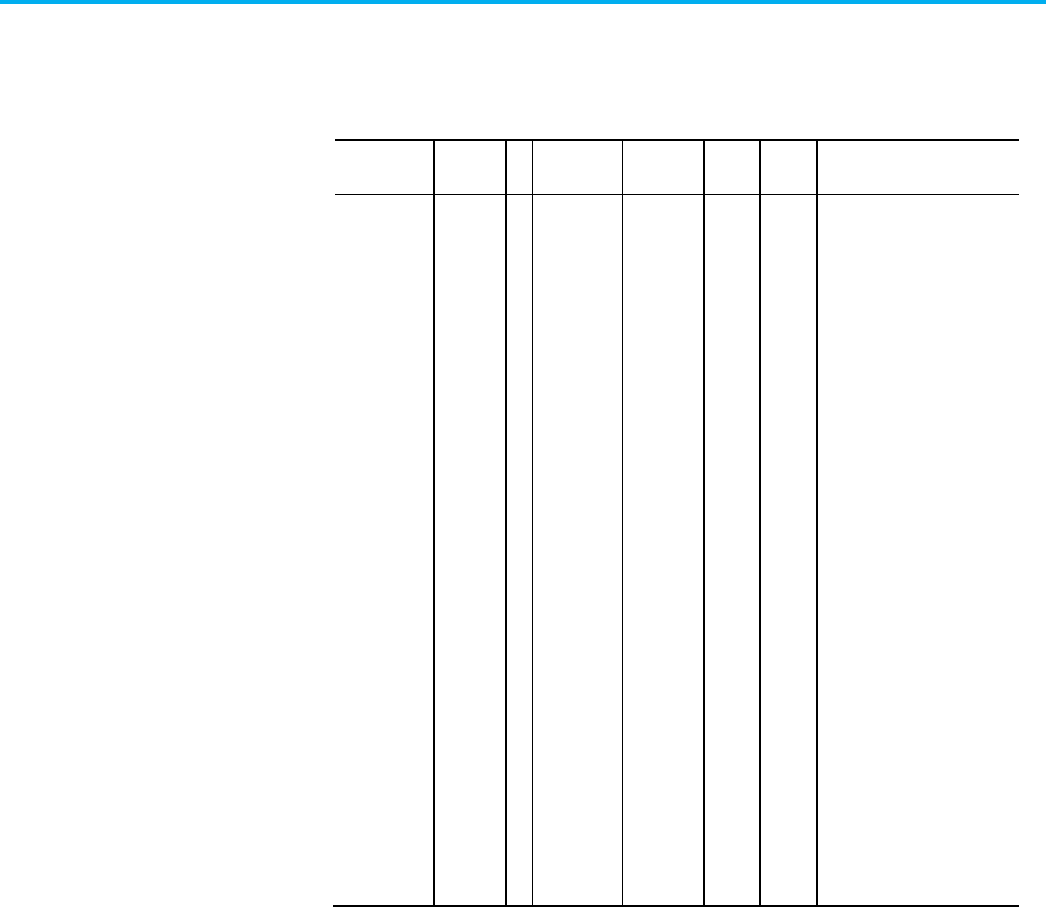
Chapter 5 Module Configuration Attributes
786 Rockwell Automation Publication MOTION-RM003O-EN-P - November 2023
Primary Bus Sharing Group
Usage Access T Data Type Default Min Max Semantics of Values
Optional - BD Set USINT 0 - - Enumeration:
0 = Standalone
1 = Bus Group 1
2 = Bus Group 2
3 = Bus Group 3
4 = Bus Group 4
5 = Bus Group 5
6 = Bus Group 6
7 = Bus Group 7
8 = Bus Group 8
9 = Bus Group 9
10 = Bus Group 10
11 = Bus Group 11
12 = Bus Group 12
13 = Bus Group 13
14 = Bus Group 14
15 = Bus Group 15
16 = Bus Group 16
17 = Bus Group 17
18 = Bus Group 18
19 = Bus Group 19
20 = Bus Group 20
21 = Bus Group 21
22 = Bus Group 22
23 = Bus Group 23
24 = Bus Group 24
25 = Bus Group 25
This enumerated selection indicates the primary Bus Sharing Group the drive
is assigned to. Physically, a Bus Sharing Group represents a collection of
drives that are wired together in a Shared AC/DC or Shared DC Bus
Configuration. Assignment to a Bus Sharing Group limits the DC Bus Unload
action initiated by a converter in the group, and the resultant Bus Power
Sharing exceptions, to Shared AC/DC and Shared DC drives in the converter's
assigned Bus Group. Drives assigned to other Bus Groups are, therefore,
unimpacted.
If the drive's Bus Configuration indicates Standalone operation, the only valid
enumeration for the Bus Sharing Group is Standalone.
If the drive's Bus Configuration indicates Shared AC/DC or Shared DC
operation, the drive should be assigned to a specific Bus Group. The
Standalone enumeration in this case is invalid.

Chapter 5 Module Configuration Attributes
Rockwell Automation Publication MOTION-RM003O-EN-P - November 2023 787
If the drive supports the optional Bus Configuration attribute, the Bus
Sharing Group is required in the drive profile implementation.

Chapter 5 Module Configuration Attributes
788 Rockwell Automation Publication MOTION-RM003O-EN-P - November 2023
Duty Select
Usage Access T Data Type Default Min Max Semantics of Values
Optional - BD Set USINT[8] [] = 0 - - Enumeration:
0 = Normal
1 = Heavy
2 = Light (O)
3-255 = (reserved)
[ Axis 1 Duty Select,
Axis 2 Duty Select,
Axis 3 Duty Select,
Axis 4 Duty Select,
Axis 5 Duty Select,
Axis 6 Duty Select,
Axis 7 Duty Select,
Axis 8 Duty Select ]
This 8-element array indicates the duty level of the drive application and
balances the continuous and intermittent overload capacity of the drive and
motor accordingly. Since this value is tied to a specific drive inverter and
motor, the setting can vary for each axis instance supported by a multi-axis
drive module. The indexed elements of this array correspond to axis instances
1 thru 8. Array elements that are not applicable or configured are set to 0.
• "Normal" Duty provides nominal continuous rating at the expense of
lower overload capacity.
• "Heavy" Duty provides highest overload capacity at the expense of a
lower continuous rating.
• "Light" Duty provides highest continuous rating at the expense of
lower overload capacity.
Specification for the continuous and overload ratings under Normal, Heavy,
and Light Duty are left to the discretion of the drive vendor.
Duty Select is used to determine the level of thermal protection for the motor
and the inverter during drive operation.
Converter AC Input Phasing
Usage Access T Data Type Default Min Max Semantics of Values
Optional -
NBD
Set USINT 0 - - Enumeration:
0 = Three-Phase (R)
1 = Single-Phase (O)
2-255 = (reserved)

Chapter 5 Module Configuration Attributes
Rockwell Automation Publication MOTION-RM003O-EN-P - November 2023 789
This attribute indicates whether the converter input power to AC line is
Single-Phase or Three-Phase.
Converter AC Input Voltage
Usage
Access
T
Data Type
Default
Min
Max
Semantics of Values
Optional -
NBD
Set UINT 230 0
Volts (RMS)
This value configures the drive for the intended AC line voltage applied to the
converter.
Demonstration Mode Select
Usage Access T Data Type Default Min Max Semantics of Values
Optional - BD Set USINT 0 0 1 Enumeration:
0 = Inactive
1 = Active
2-255 = (reserved)
Activating Demonstration Mode, or 'Demo Mode', allows the associated
converter and inverter power structures to operate using Single-Phase,
110/120 VAC, 50/60Hz, AC line input. Converter and inverter performance is
significantly limited as compared to standard operation with Demo Mode
inactive. All converter and inverter modules in a shared DC bus configuration
should have the same Demo Mode setting to avoid faulting.
The purpose of Demo Mode is to allow demonstration of products in
non-industrial environments. It is not intended for use in real motion
applications.
Mover Axis Assignment Sequence
Usage
Access
T
Data Type
Default
Min
Max
Semantics of Values
Optional - X
(Copied to
Movers)
Set USINT 0 - - Enumeration:
0 = Decreasing Position (O)
1 = Increasing Position (O)
2 = Decreasing Position from
Reference Mover (O)
3 = Increasing Position from
Reference Mover (O)
4-127 = (reserved)
128-255 = (vendor specific)
During track initialization, this attribute determines how movers on the track
are assigned to CIP Motion axis instances. Once the mover sequence is

Chapter 5 Module Configuration Attributes
790 Rockwell Automation Publication MOTION-RM003O-EN-P - November 2023
established on the track the movers are then assigned to the axis instances of
track sections that are themselves arranged in a sequence that comprise the
track, starting with Section 1.
The configured Mover Axis Assignment Sequence must be the same for all
track sections and is sent only to the section axis instance of the track section
device. This values is also stored in a private variable for each of the mover
axis instances of the controller that are associated with this section module.
This is necessary to support the APR functionality of the mover axis instances.
Decreasing Position instructs the track sections to assign movers on the track
to axis instances in a sequence starting with the mover with the highest
position value as the first mover followed by movers with decreasing position
values. The mover types on the track have no effect on the sequencing.
Increasing Position instructs the track sections to assign movers on the track
to axis instances in a sequence starting with the mover with the lowest
position value as the first mover followed by movers with increasing position
values. The mover types on the track have no effect on the sequencing.
Decreasing Position from Reference Mover instructs the track sections to
assign movers on the track to axis instances in a sequence starting with the
mover electronically identified as the Reference Mover followed by movers in
the direction of decreasing position values relative to the Reference Mover.
Increasing Position from Mover 1 instructs the track sections to assign movers
on the track to axis instances in a sequence starting with the mover
electronically identified as the Reference Mover followed by movers in the
direction of increasing position values relative to the Reference Mover.
Converter Overtemperature User Limit
Usage
Access
T
Data Type
Default
Min
Max
Semantics of Values
Optional -
NBD
Set REAL 0 0
Degrees Celsius (°C)
This attribute sets the user limit for the Converter Overtemperature UL
exception.
Converter Thermal Overload User Limit
Usage
Access
T
Data Type
Default
Min
Max
Semantics of Values
Optional -
NBD
Set REAL 100 0
% Converter Rated
This attribute sets the user limit for the Converter Thermal Overload UL
exception.

Chapter 5 Module Configuration Attributes
Rockwell Automation Publication MOTION-RM003O-EN-P - November 2023 791
Converter Ground Current User Limit
Usage
Access
T
Data Type
Default
Min
Max
Semantics of Values
Optional -
NBD
Set REAL 100 0
% Factory Limit
This attribute sets the user limit for the Converter Ground Current UL
exception.
Bus Regulator Overtemperature User Limit
Usage Access T Data Type Default Min Max Semantics of Values
Optional - BD Set REAL 0 0
Degrees Celsius (°C)
This attribute sets the user limit for the Bus Regulator Overtemperature UL
exception.
Bus Regulator Thermal Overload User Limit
Usage
Access
T
Data Type
Default
Min
Max
Semantics of Values
Optional - BD Set REAL 100 0
% Regulator Rated
This attribute sets the user limit for the Bus Regulator Thermal UL exception.
Bus Overvoltage User Limit
Usage
Access
T
Data Type
Default
Min
Max
Semantics of Values
Optional - BD Set REAL 140 0
% Nominal Bus Voltage
This attribute sets the user limit for the Bus Overvoltage UL exception. Unlike
the corresponding Factory Limit, which is specified in Volts, the User Limit is
based on the percentage of Nominal Bus Voltage during operation.
Bus Undervoltage User Limit
Usage
Access
T
Data Type
Default
Min
Max
Semantics of Values
Optional - BD Set REAL 0 0 100 % Nominal Bus Voltage
This attribute sets the user limit for the Bus Undervoltage UL exception.
Unlike the corresponding Factory Limit, which is specified in Volts, the User
Limit is based on the percentage of Nominal Bus Voltage during operation.

Chapter 5 Module Configuration Attributes
792 Rockwell Automation Publication MOTION-RM003O-EN-P - November 2023

Chapter 5 Module Configuration Attributes
Rockwell Automation Publication MOTION-RM003O-EN-P - November 2023 793
Control Module Overtemperature User Limit
Usage Access T Data Type Default Min Max Semantics of Values
Optional - All Set REAL 0 0
Degrees Celsius (°C)
This attribute sets the user limit for the Control Module Overtemperature UL
exception.
Converter Pre-Charge Overload User Limit
Usage Access T Data Type Default Min Max Semantics of Values
Optional -
NBD
Set REAL 100 0
% Converter Rated
This attribute sets the user limit for the Converter Pre-Charge Overload UL
exception.
Digital Output Configuration
Usage
Access
T
Data Type
Default
Min
Max
Semantics of Values
Optional - All Set USINT [8][8] []=0 - - Enumeration:
0 = Unassigned
1 = Contactor Enable
2 = Mechanical Brake
3 = Resistive Brake
4 = Regenerative Power
5 = Converter Power
6-255 = (reserved)
[ Axis 1 Output Config[8],
Axis 2 Output Config[8],
Axis 3 Output Config[8],
Axis 4 Output Config[8],
Axis 5 Output Config[8],
Axis 6 Output Config[8],
Axis 7 Output Config[8],
Axis 8 Output Config[8]]
This attribute is a 2 dimensional array of enumerated values that map
configurable digital output to specific functions for each drive axis. Each of
the 8 possible axis instances may support up to 8 configurable digital outputs.
The Logix controller distributes the Digital Output Configuration array
elements to each axis instance of the device. The Digital Output Configuration
attribute in the device is defined as a 32 element array of which only the first 8

Chapter 5 Module Configuration Attributes
794 Rockwell Automation Publication MOTION-RM003O-EN-P - November 2023
elements are supported by this 8x8 Digital Output Configuration array
definition. The remaining elements of the 32 element array are set to 0.
Digital Input Configuration
Usage
Access
T
Data Type
Default
Min
Max
Semantics of Values
Optional - All Set USINT [8][8] []=0 - - Enumeration:
0 = Unassigned
1 = Enable
2 = Home
3 = Registration 1
4 = Registration 2
5 = Positive Overtravel
6 = Negative Overtravel
7 = Regenerative Power OK
8 = Bus Capacitor OK
9 = Shunt Thermal Switch OK
10 = Home & Registration 1
11 = Motor Thermostat OK
12 = Pre-Charge OK
13 = AC Line Contactor OK
14 = Bus Conditioner OK
15 = Converter OK
16-255 = (reserved)
[ Axis 1 Input Config[8],
Axis 2 Input Config[8],
Axis 3 Input Config[8],
Axis 4 Input Config[8],
Axis 5 Input Config[8],
Axis 6 Input Config[8],
Axis 7 Input Config[8],
Axis 8 Input Config[8]]
This attribute is a 2 dimensional array of enumerated values that map
configurable digital inputs to specific functions for each drive axis. Each of
the 8 possible axis instances may support up to 8 configurable digital inputs.
The Logix controller distributes the Digital Input Configuration array
elements to each axis instance of the device. The Digital Input Configuration
attribute in the device is defined as a 32 element array of which only the first 8
elements are supported by this 8x8 Digital Input Configuration array
definition. The remaining elements of the 32 element array are set to 0.
Functions that are not mapped to a digital input are not checked by the drive,
and do not generate associated exceptions or events. Associated exception
actions in this case are accepted by the device and ignored.

Chapter 5 Module Configuration Attributes
Rockwell Automation Publication MOTION-RM003O-EN-P - November 2023 795
DC Bus Output Voltage Set Point n
Usage
Access
T
Data Type
Default
Min
Max
Semantics of Values
Optional - BD Set REAL 0 0
Volts
This attribute sets the reference voltage used to actively regulate the DC Bus
Output Voltage output of Bus Converter power structure instance n when in
the Running state.
Power structure instance attributes are only applicable when supporting
multiple converter power structure generated DC Bus outputs per axis object
instance
Bus Voltage Set Point n
Usage Access T Data Type Default Min Max Semantics of Values
Optional - BD Set REAL 0 0
Volts
This attribute sets the reference voltage used to actively regulate the Bus
Voltage output of Bus Converter power structure instance n when in the
Running state.
Power structure instance attributes are only applicable when supporting
multiple converter power structure generated DC Bus outputs per axis object
instance.
Bus Output Overvoltage User Limit n
Usage Access T Data Type Default Min Max Semantics of Values
Optional - BD Set REAL 0 0
% DC Bus Voltage Set Point n
This attribute sets the User Limit for the Bus Overvoltage UL exception
associated with the DC Bus output of DC converter power structure instance
n when supporting multiple converter power structure generated DC Bus
outputs per axis object instance. Unlike the corresponding Factory Limit,
which is specified in Volts, the User Limit is based on percent of the
corresponding DC Bus Voltage Set Point n during operation.
This attribute is only applicable to DC Converter Types.
Bus Output Undervoltage User Limit n
Usage
Access
T
Data Type
Default
Min
Max
Semantics of Values

Chapter 5 Module Configuration Attributes
796 Rockwell Automation Publication MOTION-RM003O-EN-P - November 2023
Optional - BD Set REAL 0 0 100 % Bus Voltage Set Point n
This attribute sets the User Limit for the Bus Undervoltage UL exception
associated with the DC Bus output of DC converter power structure instance
n when supporting multiple converter power structure generated DC Bus
outputs per axis object instance. Unlike the corresponding Factory Limit,
which is specified in Volts, the User Limit is based on percent of the
corresponding Bus Voltage Set Point n during operation.
This attribute is only applicable to DC Converter Types.
See also
Standard Exceptions on page 757
Module Feedback Port Attributes on page 796
Module Configuration Attributes on page 773
Module Axis attributes are used to configure the feedback ports of the device
module. Each device module may be equipped with multiple feedback ports
that can be freely mapped to the various feedback channels of a CIP Motion
axis instance.
Feedback Port Select
Usage
Access
T
Data Type
Default
Min
Max
Semantics of Values
Optional - E Set USINT[8][4] [] = 0 - - Enumeration:
0 = Unused
1 = Port 1
2 = Port 2
3 = Port 3
4 = Port 4
5 = Port 5
6 = Port 6
7 = Port 7
8 = Port 8
9 = Port 9
10 = Port 10
11 = Port 11
12 = Port 12
13-255 = Reserved
This attribute is organized as 8x4 array with 8 corresponding to the maximum
number of axes supported by a given drive device module and 4 representing
the number of logical feedback channels per axis. The 8x4 indexed array
elements of this array correspond to axis instances 1 thru 8 and feedback
channels 1 thru 4, respectively. The individual elements of this array are
Module Feedback Port
Attributes

Chapter 5 Module Configuration Attributes
Rockwell Automation Publication MOTION-RM003O-EN-P - November 2023 797
enumerated values associated with the 'Feedback n Port Select' attribute in the
Motion Device Axis Object. The controller's module interface function uses
the Feedback Port Select information to set the Feedback n Port Select
attributes for each axis instance of the CIP Motion device.
Feedback Card Type
Usage
Access
T
Data Type
Default
Min
Max
Semantics of Values
Optional - E
AOP
Set USINT[8][4] [] = 0 - - Feedback Card ID#
This attribute is organized as 8x4 array with 8 corresponding to the maximum
number of axes supported by a given drive device module and 4 representing
the number of logical feedback channels per axis. The individual elements of
this array are numeric identifiers associated with the specific feedback
interface hardware assigned to this feedback port. The list of supported
Feedback Types is determined by the feedback interface hardware selection.
Configuration software uses this information to filter the Feedback Type list
associated with the port. This multidimensional array follows the same
indexing rules as the Feedback Port Select.
See also
Feedback Interface Types on page 506
Module Timing Attributes on page 797
Module Configuration Attributes on page 773
The following attributes configure various time related aspects of CIP Motion
device.
Time Sync Support
Usage
Access
T
Data Type
Default
Min
Max
Semantics of Values
Required -
All
FW
Set USINT 2 - - Enumeration:
0 = No sync support
1 = Low quality
2 = High quality
3-255 = (reserved)
Controller firmware only enumerated parameter (does not go to the drive)
which reflects the time synchronization capability of the device.
• No Sync: This enumeration indicates that the device does not support
CIP Sync time synchronization and therefore cannot interpret or
generate time stamps.
Module Timing Attributes

Chapter 5 Module Configuration Attributes
798 Rockwell Automation Publication MOTION-RM003O-EN-P - November 2023
• Low Quality: This enumeration indicates that the device has a low
quality implementation of CIP Sync time synchronization protocol.
Latency associated with the software time sync algorithm limits time
stamp accuracy to no better than 10 microseconds (µsec). Fine
interpolation is not recommended for this time sync implementation.
Low Quality time synchronization is sufficient for Fault and Alarm
event logging.
• High Quality: This enumeration indicates that the device has a high
quality implementation of CIP Sync time synchronization protocol
resulting in very accurate time stamping (better than 10 µsec). High
Quality time synchronization is appropriate for fine interpolation and
registration functionality.

Chapter 5 Module Configuration Attributes
Rockwell Automation Publication MOTION-RM003O-EN-P - November 2023 799
Time Diagnostics
Usage Access T Data Type Default Min Max Semantics of Values
Required -
All
FW
Set BYTE 0 - - Bitmap:
0: Enable Time Statistics
1: Reset Transmission Statistics
2-7: (reserved)
Controller firmware only parameter (does not go to the drive) which controls
whether timing diagnostic data is requested from the drive.
• Enable Time Statistics - enable timing diagnostic data.
• Reset Transmission Statistics - when the controller sees this bit set to a
one it will reset transmission statistics and then clear the bits.
Position Loop Device Update Period
Usage
Access
T
Data Type
Default
Min
Max
Semantics of Values
Required - D Set INT - - Microseconds
Used to determine setting of Interpolation Control when in position loop
mode.
Velocity Loop Device Update Period
Usage
Access
T
Data Type
Default
Min
Max
Semantics of Values
Required - D Set INT - - Microseconds
Used to determine setting of Interpolation Control when in velocity loop
mode.
Torque Loop Device Update Period
Usage
Access
T
Data Type
Default
Min
Max
Semantics of Values
Required - D Set INT - - Microseconds
Used to determine setting of Interpolation Control when in torque loop mode.

Chapter 5 Module Configuration Attributes
800 Rockwell Automation Publication MOTION-RM003O-EN-P - November 2023
See also
Motion Control Modes on page 18
Module Support Attributes on page 800
Module Configuration Attributes on page 773
The following AOP Module C-tag parameters are used by configuration
software to determine the size of various array data needed to configure the
CIP Motion device and whether attributes associated with the converter
function will be sent to the CIP Motion device. These parameters are not
attributes of any object and are not sent to the CIP Motion device.
Number of Configured Axes
Usage
Access
T
Data Type
Default
Min
Max
Semantics of Values
Required -
All
AOP
SINT 2 0 8 # of axes
Configuration software only parameter (does not go to the device),
representing the number of axes in this device configured for use.
Inverter Support
Usage
Access
T
Data Type
Default
Min
Max
Semantics of Values
Required -
All
AOP
SINT 1 - - Bitmap:
0: Axis 1 Inverter
1: Axis 2 Inverter
2: Axis 3 Inverter
3: Axis 4 Inverter
4: Axis 5 Inverter
5: Axis 6 Inverter
6: Axis 7 Inverter
7: Axis 8 Inverter
Configuration software only bitmapped parameter (does not go to the device),
where each bit determines if an axis instance supports an Inverter power
structure. This parameter impacts Inverter specific attributes, for example,
PWM Frequency and Duty Select.
Module Support Parameters

Chapter 5 Module Configuration Attributes
Rockwell Automation Publication MOTION-RM003O-EN-P - November 2023 801
Number of Configurable Inputs
Usage Access T Data Type Default Min Max Semantics of Values
Optional - All
FW*
USINT[8] [] = 0 0 8 Number of inputs
[ Axis 1 Inputs,
Axis 2 Inputs,
Axis 3 Inputs,
Axis 4 Inputs,
Axis 5 Inputs,
Axis 6 Inputs,
Axis 7 Inputs,
Axis 8 Inputs]
Firmware only parameter (does not go to the device) that controls how much
of the Digital Input Configuration array is sent to the device for a given axis
instance.
Important:
This attribute is only needed if Digital Input Configuration is
supported.
The number of configurable inputs can vary for each axis instance supported
by a multi-axis drive module. The indexed elements of this array correspond
to axis instances 1 thru 8. Array elements that are not applicable or configured
are set to 0.
Source of Configurable Inputs
Usage
Access
T
Data Type
Default
Min
Max
Semantics of Values
Optional - All
FW*
USINT[8] [] = 0 0 8 Number of inputs
[ Axis 1 Input Source,
Axis 2 Input Source,
Axis 3 Input Source,
Axis 4 Input Source,
Axis 5 Input Source,
Axis 6 Input Source,
Axis 7 Input Source,
Axis 8 Input Source]
Firmware only parameter (does not go to the device) that specifies the axis
instance that sources the configurable digital inputs for a given axis of the
device.
Important:
This attribute is only needed if Digital Input Configuration is
supported.
While axis instances generally provide their own set of configurable inputs, in
some cases axis instances, like feedback only axis instances, utilize the digital
inputs from another axis instance. The Source of Configurable Inputs element

Chapter 5 Module Configuration Attributes
802 Rockwell Automation Publication MOTION-RM003O-EN-P - November 2023
can be used to identify another axis instance as the source for its digital
inputs. The indexed elements of this array correspond to axis instances 1 thru
8. Array elements that are not applicable or configured are set to 0.
Primary Bus Sharing Group
Usage
Access
T
Data Type
Default
Min
Max
Semantics of Values
Optional -
BD
USINT 0 - - Enumeration:
0 = Standalone
1 = Bus Group 1
2 = Bus Group 2
3 = Bus Group 3
4 = Bus Group 4
5 = Bus Group 5
6 = Bus Group 6
7 = Bus Group 7
8 = Bus Group 8
9 = Bus Group 9
10 = Bus Group 10
11 = Bus Group 11
12 = Bus Group 12
13 = Bus Group 13
14 = Bus Group 14
15 = Bus Group 15
16 = Bus Group 16
17 = Bus Group 17
18 = Bus Group 18
19 = Bus Group 19
20 = Bus Group 20
21 = Bus Group 21
22 = Bus Group 22
23 = Bus Group 23
24 = Bus Group 24
25 = Bus Group 25
This enumerated selection indicates the primary Bus Sharing Group the
device is assigned to. Physically, a Bus Sharing Group represents a collection
of devices that are wired together on a primary DC Bus with in a Shared
AC/DC, Shared DC/DC, or Shared DC Bus Configuration. Assignment to a
Bus Sharing Group limits the DC Bus Unload action initiated by a converter in
the group, and the resultant Bus Power Sharing exceptions, to Shared AC/DC,
Shared DC/DC, and Shared DC devices in the converter's assigned Bus Group.
Drives assigned to other Bus Groups are, therefore, unaffected.
If the device’s Bus Configuration indicates Standalone operation, the only
valid enumeration for the Bus Sharing Group is Standalone.

Chapter 5 Module Configuration Attributes
Rockwell Automation Publication MOTION-RM003O-EN-P - November 2023 803
If the device’s Bus Configuration indicates Shared AC/DC, Shared DC/DC, or
Shared DC operation, the device should be assigned to a specific primary Bus
Group. The Standalone enumeration in this case is invalid.
If the device’s supports the optional Bus Configuration attribute, the Bus
Sharing Group is required in the drive profile implementation.
Secondary Bus Sharing Group
Usage
Access
T
Data Type
Default
Min
Max
Semantics of Values
Optional -
BD
USINT 0 - - Enumeration:
0 = (reserved)
1 = Bus Group 1
2 = Bus Group 2
3 = Bus Group 3
4 = Bus Group 4
5 = Bus Group 5
6 = Bus Group 6
7 = Bus Group 7
8 = Bus Group 8
9 = Bus Group 9
10 = Bus Group 10
11 = Bus Group 11
12 = Bus Group 12
13 = Bus Group 13
14 = Bus Group 14
15 = Bus Group 15
16 = Bus Group 16
17 = Bus Group 17
18 = Bus Group 18
19 = Bus Group 19
20 = Bus Group 20
21 = Bus Group 21
22 = Bus Group 22
23 = Bus Group 23
24 = Bus Group 24
25 = Bus Group 25
This enumerated selection indicates the secondary Bus Sharing Group the
device is assigned to. Physically, a secondary Bus Sharing Group represents a
collection of devices that are wired together on a Secondary DC Bus with a
Shared DC/DC, or Shared DC Bus Configuration. Assignment to a Secondary
Bus Sharing Group limits the DC Bus Unload action initiated by a DC/DC
converter in the group, and the resultant Bus Power Sharing exceptions, to
Shared DC drives in the converter's assigned secondary Bus Group. Devices
assigned to other Bus Groups are, therefore, unaffected.

Chapter 5 Module Configuration Attributes
804 Rockwell Automation Publication MOTION-RM003O-EN-P - November 2023
If the Bus Configuration for a device connected to a secondary DC Bus
indicates Shared DC/DC, or Shared DC operation, the device should be
assigned to a specific Bus Group.
If the device is designed to operate on a secondary DC Bus, the optional Bus
Configuration and secondary Bus Sharing Group attributes are required in
the drive profile implementation.

Chapter 5 Module Configuration Attributes
Rockwell Automation Publication MOTION-RM003O-EN-P - November 2023 805
Cyclic Read Limits
Usage Access T Data Type Default Min Max Semantics of Values
USINT[8] [ ]=0 0 25 # of cyclic reads
[ Axis 1 Reads,
Axis 2 Reads,
Axis 3 Reads,
Axis 4 Reads,
Axis 5 Reads,
Axis 6 Reads,
Axis 7 Reads,
Axis 8 Reads]
FW only parameter (does not go to the device) but controls how many Cyclic
Read attributes can be configured for a given axis instance. The number of
configurable inputs can vary for each axis instance supported by a multi-axis
drive module. The indexed elements of this array correspond to axis instances
1 thru 8. Array elements that are not applicable or configured are set to 0.
Cyclic Write Limits
Usage
Access
T
Data Type
Default
Min
Max
Semantics of Values
USINT[8] [ ]=0 0 25 # of cyclic writes
[ Axis 1 Writes,
Axis 2 Writes,
Axis 3 Writes,
Axis 4 Writes,
Axis 5 Writes,
Axis 6 Writes,
Axis 7 Writes,
Axis 8 Writes]
FW only parameter (does not go to the device) but controls how many Cyclic
Writes attributes can be configured for a given axis instance. The number of
configurable inputs can vary for each axis instance supported by a multi-axis
drive module. The indexed elements of this array correspond to axis instances
1 thru 8. Array elements that are not applicable or configured are set to 0.

Chapter 5 Module Configuration Attributes
806 Rockwell Automation Publication MOTION-RM003O-EN-P - November 2023
Track ID
Usage Access T Data Type Default Min Max Semantics of Values
Optional - X USINT 0 - - Enumeration:
0 = Not Specified
1 = Track 1
2 = Track 2
3 = Track 3
4 = Track 4
5 = Track 5
6 = Track 6
7 = Track 7
8 = Track 8
This enumerated selection identifies the Track that the device is incorporated
into. Physically, a Track ID represents a collection of devices that are wired
together to create a unique track layout. The Track ID can be used to validate
any configurations that must be consistent across a Track definition. Devices
assigned to other Track IDs are unaffected.
If the Track ID is defined as the default value of Not Specified, validation
cannot be performed for those devices.
See also
Module Axis Attributes on page 777
Module Configuration Attributes on page 773

Index
Rockwell Automation Publication MOTION-RM003O-EN-P - November 2023 807
Index
A
Acceleration Control Behavior 31
attribute conversion from SERCOS 129
Drive supported optional attributes 132
attribute units 102
attributes
ac line condition 670
acceleration control configuration 263
APR fault 423
auto-tune configuration 401
axis exception action 429
axis exception action configuration
425
axis info 349
axis safety status 594
axis statistical 357
CIP axis status 358
Command Generation Behavior 34
command generator configuration 265
command generator signal 269
command reference generation 265
configuration fault 433
converter ac line configuration 666
converter ac line monitoring 660
converter ac line source configuration
669
converter bus voltage control
configuration 680
converter bus voltage control signal
684
converter control mode 677
converter current control configuration
690
converter current control signal 692
converter current reference
configuration 686
converter current reference signal 689
converter output 699
converter reactive power control 697
converter types 676
current control configuration 280
current control signal 287
DC bus control 649
drive general purpose I/O 381
drive output 380
event capture 376
exception factory limit info 440
exception user limit configuration 447
exception, fault and alarm 453
feedback configuration 476
frequency control configuration 296
frequency control signal 300
general feedback info 489
general feedback signal 490
general linear motor 569
general motor 571
general permanent magnet motor 578
general rotary motor 581
guard safety 610
guard safety status 611
hookup test configuration 409
hookup test result 410
identify motion axis attributes based on
device function codes 107
induction motor 582
inertia test configuration 412
inertia test result 415
interior permanent magnet motor 587
intialization faults 458
linear PM motor 584
load transmission and actuator 589
module axis 718
module class 716
module configuration block 715
module feedback port 733
module support 736
module timing 734
module/node fault and alarm 462
motion control configuration 492
motion control interface 500
motion control signal 508
motion control status 518
motion database storage 530
motion dynamic configuration 534
motion homing configuration 538
motion planner configuration 549
motion planner output 555
motion scaling 556
motor test result 418
position loop configuration 303
position loop signal 301
power and thermal management
configuration 389

Index
808 Rockwell Automation Publication MOTION-RM003O-EN-P - November 2023
power and thermal managment status
390
required vs optional axis attributes 104
rotary PM motor 591
standard initialization 459
standard start inhibits 646
start inhibits 645
stopping and braking 623
torque/force control configuration 307
torque/force control signal 336
velocity loop configuration 338
velocity loop signal 345
Axis Test Mode 25, 593, 675
B
Behavior models 31
Acceleration Control Behavior 31
Command Generation Behavior 34
Current Control Behavior 41
Event Capture Behavior 44
Fault and Alarm Behavior 46
Motion Control Axis Behavior 59
C
CIP data types 103
Control Methods 23
No Control Mode 23
Position Control Mode 20
Torque Control Mode 22
Velocity Control Mode 21
Current Control Behavior 41
D
device function codes 103
Drive supported optional attributes 132
E
Event Capture Behavior 44
exceptions 699
F
Fault and Alarm Behavior 46
I
identify motion axis attributes based on
device function codes 107
Integrated Motion Axis Control Modes and
Methods 18
M
Motion Control Axis Behavior 59
N
No Control Mode 23
P
Position Control Mode 20
R
required vs optional axis attributes 104
Rockwell Automation specific initialization
459
Rockwell Automation specific start inhibits
647
T
Torque Control Mode 22
V
Velocity Control Mode 21

Allen-Bradley, expanding human possibility, Logix, Rockwell Automation, and Rockwell Software are trademarks of Rockwell Automation, Inc.
EtherNet/IP is a trademark of ODVA, Inc.
Trademarks not belonging to Rockwell Automation are property of their respective companies.
Rockwell Otomayson Ticaret A.Ş. Kar Plaza İş Merkezi E Blok Kat:6 34752, İçerenkÖy, İstanbul, Tel: +90 (216) 5698400 EEE YÖnetmeliğine Uygundur
Rockwell Automation Publication MOTION-RM003O-EN-P - November 2023
Supercedes Publication MOTION-RM003N-EN-P - November 2022 Copyright © 2023 Rockwell Automation Technologies, Inc. All Rights Reserved. Printed in the U.S.A.
Rockwell Automation support
Use these resources to access support information.
Technical Support Center
Find help with how-to videos, FAQs, chat, user forums, and product notification
updates.
rok.auto/support
Knowledgebase
Access Knowledgebase articles.
rok.auto/knowledgebase
Local Technical Support Phone Numbers
Locate the telephone number for your country. rok.auto/phonesupport
Literature Library
Find installation instructions, manuals, brochures, and technical data publications. rok.auto/literature
Product Compatibility and Download Center
(PCDC)
Get help determining how products interact, check features and capabilities, and
find associated firmware.
rok.auto/pcdc
Documentation feedback
Your comments help us serve your documentation needs better. If you have any suggestions on how to improve our content, complete the form at
rok.auto/docfeedback.
Waste Electrical and Electronic Equipment (WEEE)
Note: At the end of life, this equipment should be collected separately from any unsorted municipal
waste.
Rockwell Automation maintains current environmental information on its website at rok.auto/pec.
